Page 1621 of 2453
GD(H6DO)-9
Diagnostic Trouble Code (DTC) Detecting Criteria
GENERAL DESCRIPTION
2. Diagnostic Trouble Code (DTC) Detecting Criteria
A: DTC P0011 INTAKE CAMSHAFT POSITION TIMING - OVER-ADVANCED
(BANK 1)
1. OUTLINE OF DIAGNOSIS
Detect the AVCS system malfunction.
There are two types of diagnosis: Crankshaft cam timing diagnosis; and slow response diagnosis. Either of
these is performed according to the status of the engine while running.
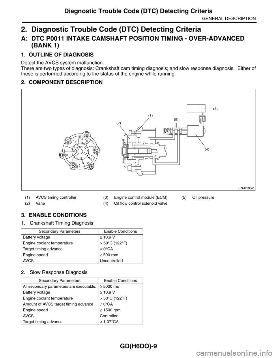
2. COMPONENT DESCRIPTION
3. ENABLE CONDITIONS
1. Crankshaft Timing Diagnosis
2. Slow Response Diagnosis
(1) AVCS timing controller (3) Engine control module (ECM) (5) Oil pressure
(2) Vane (4) Oil flow control solenoid valve
Secondary Parameters Enable Conditions
Battery voltage≥ 10.9 V
Engine coolant temperature > 50°C (122°F)
Ta r g e t t i m i n g a d v a n c e = 0 ° C A
Engine speed≥ 500 rpm
AV C S U n c o n t r o l l e d
Secondary Parameters Enable Conditions
All secondary parameters are executable.≥ 5000 ms
Battery voltage≥ 10.9 V
Engine coolant temperature > 50°C (122°F)
Amount of AVCS target timing advance≠ 0°CA
Engine speed≥ 1500 rpm
AV C S C o n t r o l l e d
Ta r g e t t i m i n g a d v a n c e < 1 . 0 7 ° C A
EN-01852
(3)
(4)
(1)(5)(2)
Page 1622 of 2453
GD(H6DO)-10
Diagnostic Trouble Code (DTC) Detecting Criteria
GENERAL DESCRIPTION
4. GENERAL DRIVING CYCLE
1. Crankshaft Timing Diagnosis
Perform the diagnosis continuously after starting engine and while AVCS is not operating.
2. Slow Response Diagnosis
Perform the diagnosis continuously after warm-up, while AVCS is operating and the target timing advance is
small.
5. DIAGNOSTIC METHOD
1. Crankshaft Timing Diagnosis
Judge as NG when the timing advance is large. Judge as OK when it is small.
Judge as NG when all the following conditions are established and the continuous time is more than 20 sec-
onds. Judge as OK and clear the NG when the following conditions are not established and the continuous
time is more than one second.
Time Needed for Diagnosis: 20 seconds
Malfunction Indicator Light Illumination: Illuminates when malfunctions occur in 2 continuous driving cycles.
2. Slow Response Diagnosis
Calculates (integrate by positive and negative separately) the AVCS deviation amount when the timing ad-
vance is large. Judges NG if the integrated value is large after 30 seconds has passed, and judges OK if it
is small.
Abnormality Judgment
When all of the following conditions are established, judged as OK.
Time Needed for Diagnosis: 30 seconds
Malfunction Indicator Light Illumination: Illuminates when malfunctions occur in 2 continuous driving cy-
cles.
Normality Judgment
Judges OK when all of the following conditions are established, and clears the NG.
Judgment Value
Malfunction Criteria Threshold Value
Basic timing advance < –18°CA
or
> 18°CA
Judgment Value
Malfunction Criteria Threshold Value
AV C S t a r g e t p o s i t i o n≥ 0°CA
Ta r g e t t i m i n g a d v a n c e l a r g e i n t e g r a t e d
counter
30 seconds or more
AV C S p o s i t i v e d ev i a t i o n i n t e g r a t e d va l u e
or
AV C S n e g a t i v e d ev i a t i o n i n t e g r a t e d
value
> 8000 (R Bank)°CA
8000 (L Bank)
< –2500 (R Bank)°CA
–2500 (L Bank)
Judgment Value
Malfunction Criteria Threshold Value
AV C S t a r g e t p o s i t i o n≥ 0°CA
Ta r g e t t i m i n g a d v a n c e l a r g e i n t e g r a t e d
counter
30 seconds or more
AV C S p o s i t i v e d ev i a t i o n i n t e g r a t e d va l u e
or
AV C S n e g a t i v e d ev i a t i o n i n t e g r a t e d
value
≤ 8000 (R Bank)°CA
8000 (L Bank)
≥ –2500 (R Bank)°CA
–2500 (L Bank)
Page 1625 of 2453
GD(H6DO)-13
Diagnostic Trouble Code (DTC) Detecting Criteria
GENERAL DESCRIPTION
2. COMPONENT DESCRIPTION
The variable valve lift system optimizes the intake valve lift by switching between the low lift cam and the high
lift cam according to the engine RPM. The amount of intake valve lift is varied by controlling the oil switching
solenoid valve duty according to signals from the ECM.
3. ENABLE CONDITIONS
(A) When at low speed (B) When at high speed
(1) Oil switching solenoid valve
Secondary Parameters Enable Conditions
Battery voltage≥ 10.9 V
After engine starting≥ 6 sec.
Engine oil temperature≥ 0°C (0°F)
Va r i a b l e va l v e l i f t c o n t r o l O p e r a t i o n
EN-03119
(1)
(B)
(A)
Page 1626 of 2453
GD(H6DO)-14
Diagnostic Trouble Code (DTC) Detecting Criteria
GENERAL DESCRIPTION
4. GENERAL DRIVING CYCLE
Perform the diagnosis continuously 6 seconds after engine start while variable valve lift is being controlled.
5. DIAGNOSTIC METHOD
Abnormality Judgment
Judge as NG when the continuous time is longer than the predetermined time when the following conditions
are established.
Time Needed for Diagnosis:
Low side 0.784 seconds
High side: 3.0 seconds
Malfunction Indicator Light: Illuminates as soon as a malfunction occurs.
Normality Judgment
When the continuous time is more than 3 seconds while the following conditions are established, judge as
OK and clear the NG.
6. DTC CLEAR CONDITION
•When the OK idling cycle is completed 40 times in a row
•When “Clear Memory” is performed
7. MALFUNCTION INDICATOR LIGHT CLEAR CONDITIONS
•When the OK driving cycle is completed 3 times in a row
•When “Clear Memory” is performed
8. FAIL SAFE
None
9. ECM OPERATION AT DTC SETTING
Memorize the freeze frame data. (For test mode $02)
Judgment Value
Malfunction Criteria Threshold Value
Low NG
Duty ratio≥ 62%
Va r i a b l e va l v e l i f t d i a g n o s i s o i l p r e s s u r e
switch
OFF
High NG
Duty ratio < 33%
Va r i a b l e va l v e l i f t d i a g n o s i s o i l p r e s s u r e
switch
ON
Judgment Value
Malfunction Criteria Threshold Value
Low OK
Duty ratio≥ 62%
Va r i a b l e va l v e l i f t d i a g n o s i s o i l p r e s s u r e
switch
ON
High OK
Duty ratio < 33%
Va r i a b l e va l v e l i f t d i a g n o s i s o i l p r e s s u r e
switch
OFF
Page 1627 of 2453
GD(H6DO)-15
Diagnostic Trouble Code (DTC) Detecting Criteria
GENERAL DESCRIPTION
F: DTC P0028 INTAKE VALVE CONTROL SOLENOID CIRCUIT RANGE/PER-
FORMANCE (BANK 2)
NOTE:
For diagnostic procedures, refer to DTC P0026.
TROL SOLENOID CIRCUIT RANGE/PERFORMANCE (BANK 1), Diagnostic Trouble Code (DTC) Detecting
Criteria.>
G: DTC P0030 HO2S HEATER CONTROL CIRCUIT (BANK 1 SENSOR 1)
1. OUTLINE OF DIAGNOSIS
Detect functional errors of the front oxygen (A/F) sensor heater.
Judge as NG when it is determined that the front oxygen (A/F) sensor impedance is large when looking at en-
gine status such as deceleration fuel cut.
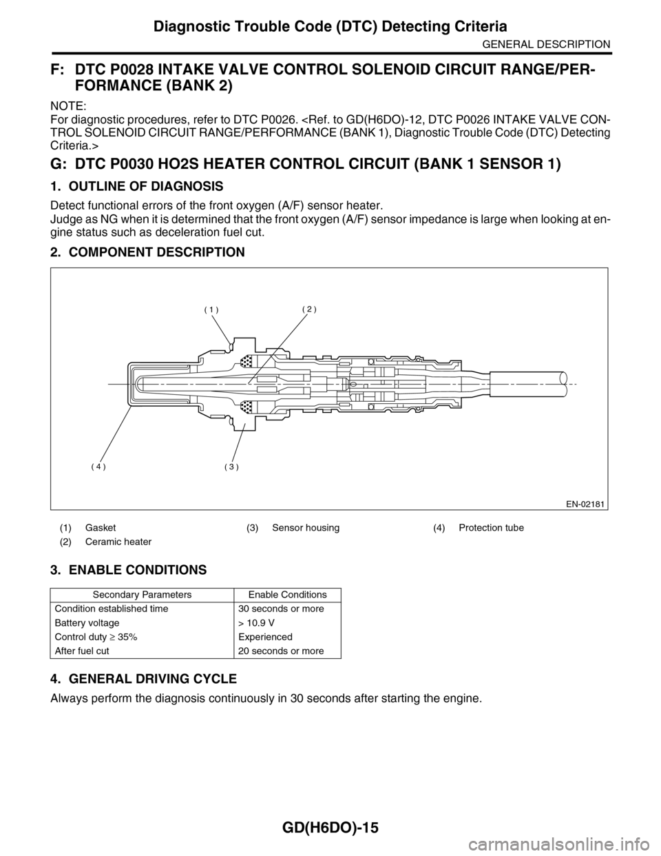
2. COMPONENT DESCRIPTION
3. ENABLE CONDITIONS
4. GENERAL DRIVING CYCLE
Always perform the diagnosis continuously in 30 seconds after starting the engine.
(1) Gasket (3) Sensor housing (4) Protection tube
(2) Ceramic heater
Secondary Parameters Enable Conditions
Condition established time 30 seconds or more
Battery voltage > 10.9 V
Control duty ≥ 35% Experienced
After fuel cut 20 seconds or more
EN-02181
( 1 )( 2 )
( 3 )( 4 )
Page 1633 of 2453
GD(H6DO)-21
Diagnostic Trouble Code (DTC) Detecting Criteria
GENERAL DESCRIPTION
J: DTC P0037 HO2S HEATER CONTROL CIRCUIT LOW (BANK 1 SENSOR 2)
1. OUTLINE OF DIAGNOSIS
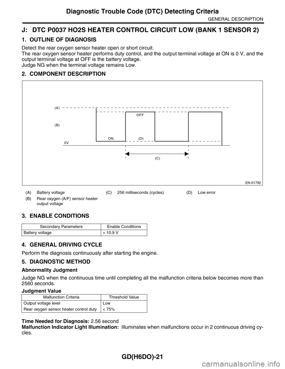
Detect the rear oxygen sensor heater open or short circuit.
The rear oxygen sensor heater performs duty control, and the output terminal voltage at ON is 0 V, and the
output terminal voltage at OFF is the battery voltage.
Judge NG when the terminal voltage remains Low.
2. COMPONENT DESCRIPTION
3. ENABLE CONDITIONS
4. GENERAL DRIVING CYCLE
Perform the diagnosis continuously after starting the engine.
5. DIAGNOSTIC METHOD
Abnormality Judgment
Judge NG when the continuous time until completing all the malfunction criteria below becomes more than
2560 seconds.
Time Needed for Diagnosis: 2.56 second
Malfunction Indicator Light Illumination: Illuminates when malfunctions occur in 2 continuous driving cy-
cles.
(A) Battery voltage (C) 256 milliseconds (cycles) (D) Low error
(B) Rear oxygen (A/F) sensor heater
output voltage
Secondary Parameters Enable Conditions
Battery voltage > 10.9 V
Judgment Value
Malfunction Criteria Threshold Value
Output voltage level Low
Rear oxygen sensor heater control duty < 75%
EN-01792
(C)
(A)
(B)
ON
OFF
0V(D)
Page 1635 of 2453
GD(H6DO)-23
Diagnostic Trouble Code (DTC) Detecting Criteria
GENERAL DESCRIPTION
K: DTC P0038 HO2S HEATER CONTROL CIRCUIT HIGH (BANK 1 SENSOR 2)
1. OUTLINE OF DIAGNOSIS
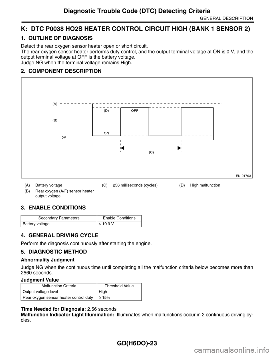
Detect the rear oxygen sensor heater open or short circuit.
The rear oxygen sensor heater performs duty control, and the output terminal voltage at ON is 0 V, and the
output terminal voltage at OFF is the battery voltage.
Judge NG when the terminal voltage remains High.
2. COMPONENT DESCRIPTION
3. ENABLE CONDITIONS
4. GENERAL DRIVING CYCLE
Perform the diagnosis continuously after starting the engine.
5. DIAGNOSTIC METHOD
Abnormality Judgment
Judge NG when the continuous time until completing all the malfunction criteria below becomes more than
2560 seconds.
Time Needed for Diagnosis: 2.56 seconds
Malfunction Indicator Light Illumination: Illuminates when malfunctions occur in 2 continuous driving cy-
cles.
(A) Battery voltage (C) 256 milliseconds (cycles) (D) High malfunction
(B) Rear oxygen (A/F) sensor heater
output voltage
Secondary Parameters Enable Conditions
Battery voltage > 10.9 V
Judgment Value
Malfunction Criteria Threshold Value
Output voltage level High
Rear oxygen sensor heater control duty≥ 15%
EN-01793
(C)
(A)
(B)
ON
OFF
0V
(D)
Page 1638 of 2453
GD(H6DO)-26
Diagnostic Trouble Code (DTC) Detecting Criteria
GENERAL DESCRIPTION
Q: DTC P0068 MAP/MAF - THROTTLE POSITION CORRELATION
1. OUTLINE OF DIAGNOSIS
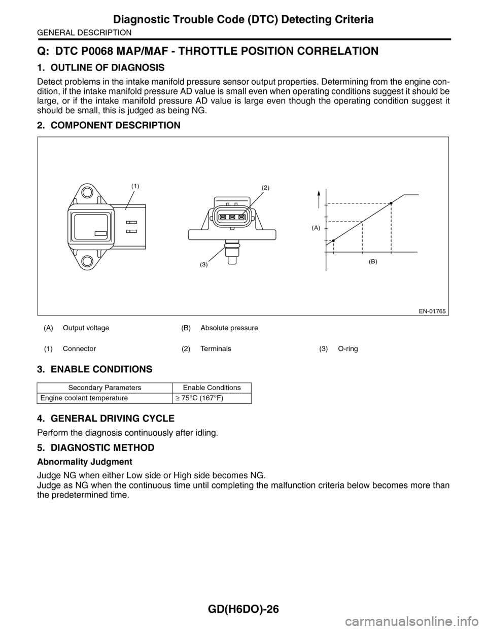
Detect problems in the intake manifold pressure sensor output properties. Determining from the engine con-
dition, if the intake manifold pressure AD value is small even when operating conditions suggest it should be
large, or if the intake manifold pressure AD value is large even though the operating condition suggest it
should be small, this is judged as being NG.
2. COMPONENT DESCRIPTION
3. ENABLE CONDITIONS
4. GENERAL DRIVING CYCLE
Perform the diagnosis continuously after idling.
5. DIAGNOSTIC METHOD
Abnormality Judgment
Judge NG when either Low side or High side becomes NG.
Judge as NG when the continuous time until completing the malfunction criteria below becomes more than
the predetermined time.
(A) Output voltage (B) Absolute pressure
(1) Connector (2) Terminals (3) O-ring
Secondary Parameters Enable Conditions
Engine coolant temperature≥ 75°C (167°F)
EN-01765
(B)
(A)
(2)
(3)
(1)