Page 1707 of 2453
GD(H6DO)-95
Diagnostic Trouble Code (DTC) Detecting Criteria
GENERAL DESCRIPTION
Normality Judgment
When the following conditions are established, it is OK.
5. DTC CLEAR CONDITION
•When the OK idling cycle is completed 40 times in a row
•When “Clear Memory” is performed
6. MALFUNCTION INDICATOR LIGHT CLEAR CONDITIONS
•When the OK driving cycle is completed 3 times in a row
•When “Clear Memory” is performed
7. FAIL SAFE
Oil temperature sensor process: Engine oil temperature is fixed at 70°C (158°F).
8. ECM OPERATION AT DTC SETTING
Memorize the freeze frame data. (For test mode $02)
Judgment Value
Malfunction Criteria Threshold Value
Engine oil temperature≥ 15°C (59°F)
Page 1708 of 2453
GD(H6DO)-96
Diagnostic Trouble Code (DTC) Detecting Criteria
GENERAL DESCRIPTION
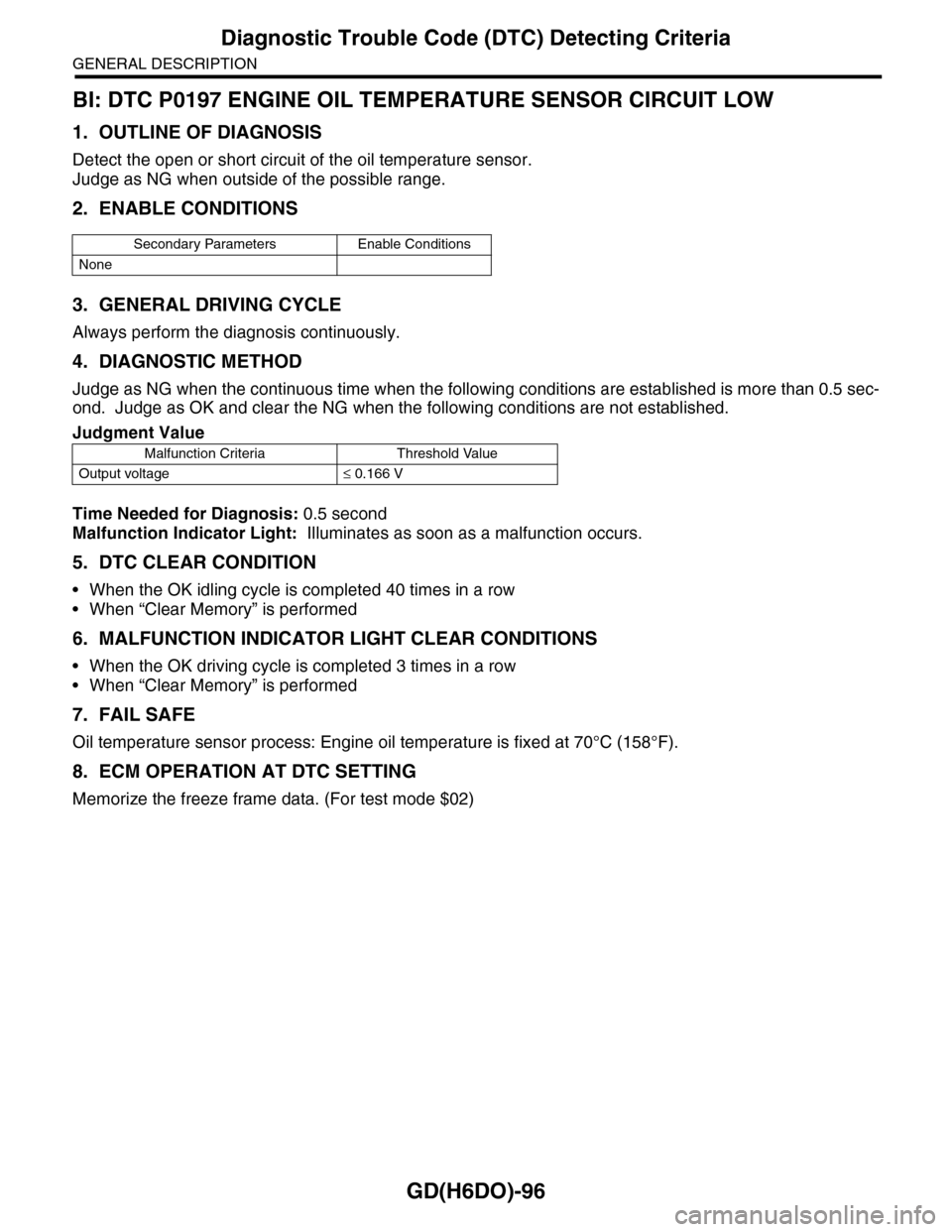
BI: DTC P0197 ENGINE OIL TEMPERATURE SENSOR CIRCUIT LOW
1. OUTLINE OF DIAGNOSIS
Detect the open or short circuit of the oil temperature sensor.
Judge as NG when outside of the possible range.
2. ENABLE CONDITIONS
3. GENERAL DRIVING CYCLE
Always perform the diagnosis continuously.
4. DIAGNOSTIC METHOD
Judge as NG when the continuous time when the following conditions are established is more than 0.5 sec-
ond. Judge as OK and clear the NG when the following conditions are not established.
Time Needed for Diagnosis: 0.5 second
Malfunction Indicator Light: Illuminates as soon as a malfunction occurs.
5. DTC CLEAR CONDITION
•When the OK idling cycle is completed 40 times in a row
•When “Clear Memory” is performed
6. MALFUNCTION INDICATOR LIGHT CLEAR CONDITIONS
•When the OK driving cycle is completed 3 times in a row
•When “Clear Memory” is performed
7. FAIL SAFE
Oil temperature sensor process: Engine oil temperature is fixed at 70°C (158°F).
8. ECM OPERATION AT DTC SETTING
Memorize the freeze frame data. (For test mode $02)
Secondary Parameters Enable Conditions
None
Judgment Value
Malfunction Criteria Threshold Value
Output voltage≤ 0.166 V
Page 1709 of 2453
GD(H6DO)-97
Diagnostic Trouble Code (DTC) Detecting Criteria
GENERAL DESCRIPTION
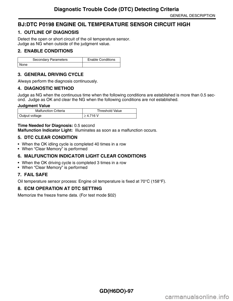
BJ:DTC P0198 ENGINE OIL TEMPERATURE SENSOR CIRCUIT HIGH
1. OUTLINE OF DIAGNOSIS
Detect the open or short circuit of the oil temperature sensor.
Judge as NG when outside of the judgment value.
2. ENABLE CONDITIONS
3. GENERAL DRIVING CYCLE
Always perform the diagnosis continuously.
4. DIAGNOSTIC METHOD
Judge as NG when the continuous time when the following conditions are established is more than 0.5 sec-
ond. Judge as OK and clear the NG when the following conditions are not established.
Time Needed for Diagnosis: 0.5 second
Malfunction Indicator Light: Illuminates as soon as a malfunction occurs.
5. DTC CLEAR CONDITION
•When the OK idling cycle is completed 40 times in a row
•When “Clear Memory” is performed
6. MALFUNCTION INDICATOR LIGHT CLEAR CONDITIONS
•When the OK driving cycle is completed 3 times in a row
•When “Clear Memory” is performed
7. FAIL SAFE
Oil temperature sensor process: Engine oil temperature is fixed at 70°C (158°F).
8. ECM OPERATION AT DTC SETTING
Memorize the freeze frame data. (For test mode $02)
Secondary Parameters Enable Conditions
None
Judgment Value
Malfunction Criteria Threshold Value
Output voltage≥ 4.716 V
Page 1710 of 2453
GD(H6DO)-98
Diagnostic Trouble Code (DTC) Detecting Criteria
GENERAL DESCRIPTION
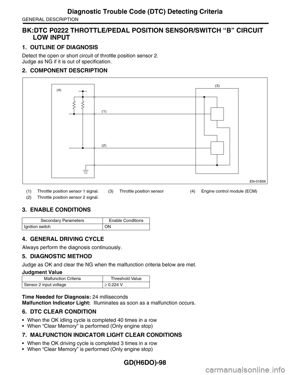
BK:DTC P0222 THROTTLE/PEDAL POSITION SENSOR/SWITCH “B” CIRCUIT
LOW INPUT
1. OUTLINE OF DIAGNOSIS
Detect the open or short circuit of throttle position sensor 2.
Judge as NG if it is out of specification.
2. COMPONENT DESCRIPTION
3. ENABLE CONDITIONS
4. GENERAL DRIVING CYCLE
Always perform the diagnosis continuously.
5. DIAGNOSTIC METHOD
Judge as OK and clear the NG when the malfunction criteria below are met.
Time Needed for Diagnosis: 24 milliseconds
Malfunction Indicator Light: Illuminates as soon as a malfunction occurs.
6. DTC CLEAR CONDITION
•When the OK idling cycle is completed 40 times in a row
•When “Clear Memory” is performed (Only engine stop)
7. MALFUNCTION INDICATOR LIGHT CLEAR CONDITIONS
•When the OK driving cycle is completed 3 times in a row
•When “Clear Memory” is performed (Only engine stop)
(1) Throttle position sensor 1 signal. (3) Throttle position sensor (4) Engine control module (ECM)
(2) Throttle position sensor 2 signal.
Secondary Parameters Enable Conditions
Ignition switch ON
Judgment Value
Malfunction Criteria Threshold Value
Sensor 2 input voltage≥ 0.224 V
EN-01859
(1)
(2)
(3)(4)
Page 1712 of 2453
GD(H6DO)-100
Diagnostic Trouble Code (DTC) Detecting Criteria
GENERAL DESCRIPTION
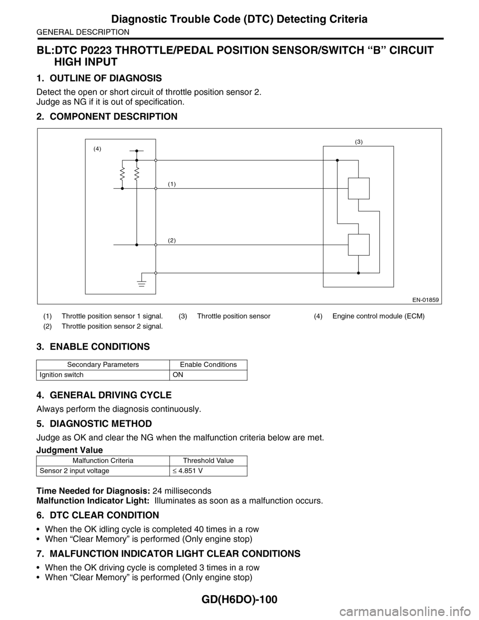
BL:DTC P0223 THROTTLE/PEDAL POSITION SENSOR/SWITCH “B” CIRCUIT
HIGH INPUT
1. OUTLINE OF DIAGNOSIS
Detect the open or short circuit of throttle position sensor 2.
Judge as NG if it is out of specification.
2. COMPONENT DESCRIPTION
3. ENABLE CONDITIONS
4. GENERAL DRIVING CYCLE
Always perform the diagnosis continuously.
5. DIAGNOSTIC METHOD
Judge as OK and clear the NG when the malfunction criteria below are met.
Time Needed for Diagnosis: 24 milliseconds
Malfunction Indicator Light: Illuminates as soon as a malfunction occurs.
6. DTC CLEAR CONDITION
•When the OK idling cycle is completed 40 times in a row
•When “Clear Memory” is performed (Only engine stop)
7. MALFUNCTION INDICATOR LIGHT CLEAR CONDITIONS
•When the OK driving cycle is completed 3 times in a row
•When “Clear Memory” is performed (Only engine stop)
(1) Throttle position sensor 1 signal. (3) Throttle position sensor (4) Engine control module (ECM)
(2) Throttle position sensor 2 signal.
Secondary Parameters Enable Conditions
Ignition switch ON
Judgment Value
Malfunction Criteria Threshold Value
Sensor 2 input voltage≤ 4.851 V
EN-01859
(1)
(2)
(3)(4)
Page 1714 of 2453
GD(H6DO)-102
Diagnostic Trouble Code (DTC) Detecting Criteria
GENERAL DESCRIPTION
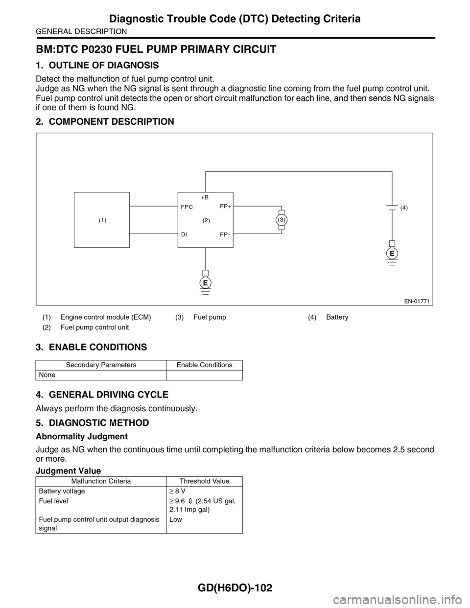
BM:DTC P0230 FUEL PUMP PRIMARY CIRCUIT
1. OUTLINE OF DIAGNOSIS
Detect the malfunction of fuel pump control unit.
Judge as NG when the NG signal is sent through a diagnostic line coming from the fuel pump control unit.
Fuel pump control unit detects the open or short circuit malfunction for each line, and then sends NG signals
if one of them is found NG.
2. COMPONENT DESCRIPTION
3. ENABLE CONDITIONS
4. GENERAL DRIVING CYCLE
Always perform the diagnosis continuously.
5. DIAGNOSTIC METHOD
Abnormality Judgment
Judge as NG when the continuous time until completing the malfunction criteria below becomes 2.5 second
or more.
(1) Engine control module (ECM) (3) Fuel pump (4) Battery
(2) Fuel pump control unit
Secondary Parameters Enable Conditions
None
Judgment Value
Malfunction Criteria Threshold Value
Battery voltage≥ 8 V
Fuel level≥ 9.6 2 (2.54 US gal,
2.11 Imp gal)
Fuel pump control unit output diagnosis
signal
Low
EN-01771
E
E
(3)
(4)
(2)
FPC
DI
FP+
FP-
+B
(1)
Page 1716 of 2453
GD(H6DO)-104
Diagnostic Trouble Code (DTC) Detecting Criteria
GENERAL DESCRIPTION
BN:DTC P0301 CYLINDER 1 MISFIRE DETECTED
1. OUTLINE OF DIAGNOSIS
Detect the presence of misfire occurrence. (Revolution fluctuation method)
Monitoring Misfire which influences exhaust deterioration (1.5 times of FTP) and catalyst damage is made
obligatory by the law. Misfire affecting these two has three patterns below. Intermittent misfire (Different cyl-
inders misfire intermittently.):
•Intermittent misfire (The same cylinder misfires in random, or different cylinders misfire in random.): FTP
1.5 times misfire
•Every time misfire (The same cylinder misfires every time.): FTP 1.5 times misfire, Catalyst damage misfire
The following detecting methods are adopted for these detection.
1) Intermittent misfire: FTP 1.5 times misfire
•120° Interval Difference Method
•360° Interval Difference Method (whole range)
•720° Interval Difference Method (3,000 rpm or less)
2) Misfire every time: FTP 1.5 times misfire, Catalyst damage misfire
•360° Interval Difference Method
2. ENABLE CONDITIONS
Map 3
3. GENERAL DRIVING CYCLE
•If conditions are met, detect misfire from idling to high rotation.
•Perform the diagnosis continuously.
Secondary Parameters Enable Conditions
All secondary parameters enable condi-
tions
1 second or more
120° Intake manifold pressure change at
CA
< 20 kPa (150 mmHg,
5.9 inHg)
Throttle position change during 16 milli-
seconds
< 20°
Fuel shut-off function Not in operation
Fuel level≥ 9.6 2 (2.54 US gal,
2.11 Imp gal)
Ve h i c l e d y n a m i c c o n t r o l o r AT t o r q u e
control
Not in operation
Evaporative system leak check Not in operation
Engine speed 400 — 8000 rpm
Intake manifold pressure >Value of Map 3 or
more
Battery voltage≥ 8 V
Atmospheric pressure≥ 75.0 kPa (563
mmHg, 22.17 inHg)
Fuel parameter determination Not extremely low vol-
atility
rpm 700 1000 1500 2000 2500 3000 3500 4000 4500 5000 5500 6000 6500 7000
kPa
(mmHg,
inHg)
26.7
(200.0,
7.87)
26.7
(200.0,
7.87)
24.0
(180.0,
7.09)
24.1
(181.0,
7.13)
24.3
(182.0,
7.17)
24.7
(185.0,
7.28)
28.3
(212.3,
8.36)
30.9
(232.1,
9.14)
32.9
(247.0,
9.72)
33.1
(248.0,
9.76)
34.3
(257.0,
10.12)
38.1
(286.0,
11.26)
41.9
(314.0,
12.36)
48.9
(367.0,
14.45)
Page 1717 of 2453
GD(H6DO)-105
Diagnostic Trouble Code (DTC) Detecting Criteria
GENERAL DESCRIPTION
4. DIAGNOSTIC METHOD
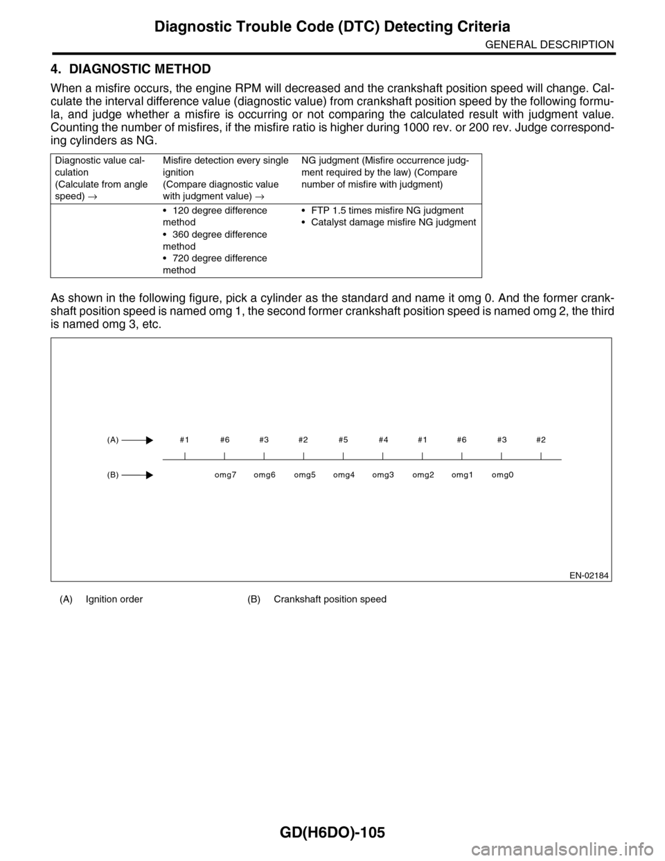
When a misfire occurs, the engine RPM will decreased and the crankshaft position speed will change. Cal-
culate the interval difference value (diagnostic value) from crankshaft position speed by the following formu-
la, and judge whether a misfire is occurring or not comparing the calculated result with judgment value.
Counting the number of misfires, if the misfire ratio is higher during 1000 rev. or 200 rev. Judge correspond-
ing cylinders as NG.
As shown in the following figure, pick a cylinder as the standard and name it omg 0. And the former crank-
shaft position speed is named omg 1, the second former crankshaft position speed is named omg 2, the third
is named omg 3, etc.
Diagnostic value cal-
culation
(Calculate from angle
speed) →
Misfire detection every single
ignition
(Compare diagnostic value
with judgment value) →
NG judgment (Misfire occurrence judg-
ment required by the law) (Compare
number of misfire with judgment)
•120 degree difference
method
•360 degree difference
method
•720 degree difference
method
•FTP 1.5 times misfire NG judgment
•Catalyst damage misfire NG judgment
(A) Ignition order (B) Crankshaft position speed
EN-02184
#1 #6 #3 #2 #5 #4 #1 #6 #3 #2(A)
(B)omg0omg1omg2omg3omg4omg5omg6omg7