2009 SUBARU TRIBECA suspension
[x] Cancel search: suspensionPage 1080 of 2453
VDC(diag)-88
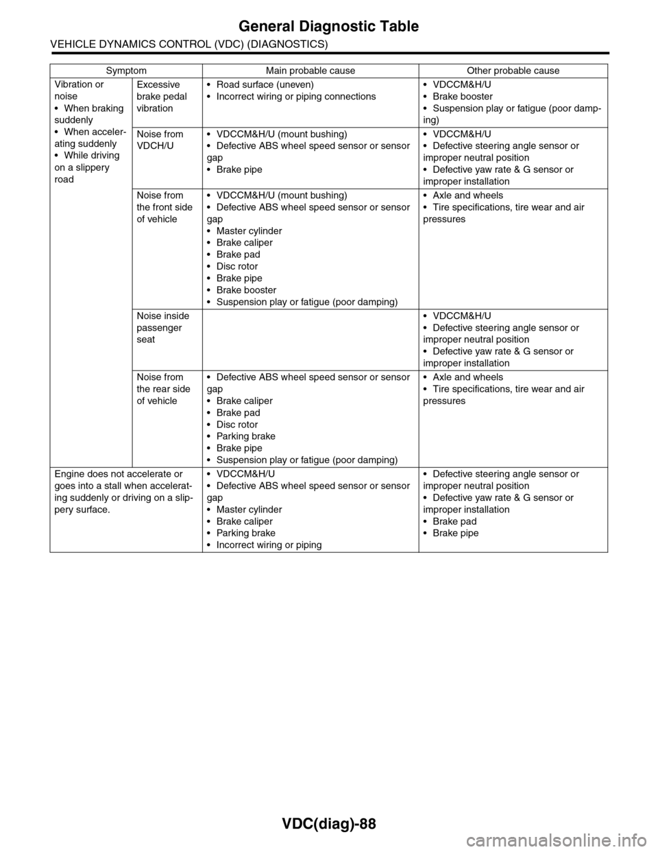
General Diagnostic Table
VEHICLE DYNAMICS CONTROL (VDC) (DIAGNOSTICS)
Vibration or
noise
•When braking
suddenly
•When acceler-
ating suddenly
•While driving
on a slippery
road
Excessive
brake pedal
vibration
•Road surface (uneven)
•Incorrect wiring or piping connections
•VDCCM&H/U
•Brake booster
•Suspension play or fatigue (poor damp-
ing)
Noise from
VDCH/U
•VDCCM&H/U (mount bushing)
•Defective ABS wheel speed sensor or sensor
gap
•Brake pipe
•VDCCM&H/U
•Defective steering angle sensor or
improper neutral position
•Defective yaw rate & G sensor or
improper installation
Noise from
the front side
of vehicle
•VDCCM&H/U (mount bushing)
•Defective ABS wheel speed sensor or sensor
gap
•Master cylinder
•Brake caliper
•Brake pad
•Disc rotor
•Brake pipe
•Brake booster
•Suspension play or fatigue (poor damping)
•Axle and wheels
•Tire specifications, tire wear and air
pressures
Noise inside
passenger
seat
•VDCCM&H/U
•Defective steering angle sensor or
improper neutral position
•Defective yaw rate & G sensor or
improper installation
Noise from
the rear side
of vehicle
•Defective ABS wheel speed sensor or sensor
gap
•Brake caliper
•Brake pad
•Disc rotor
•Parking brake
•Brake pipe
•Suspension play or fatigue (poor damping)
•Axle and wheels
•Tire specifications, tire wear and air
pressures
Engine does not accelerate or
goes into a stall when accelerat-
ing suddenly or driving on a slip-
pery surface.
•VDCCM&H/U
•Defective ABS wheel speed sensor or sensor
gap
•Master cylinder
•Brake caliper
•Parking brake
•Incorrect wiring or piping
•Defective steering angle sensor or
improper neutral position
•Defective yaw rate & G sensor or
improper installation
•Brake pad
•Brake pipe
Symptom Main probable cause Other probable cause
Page 1081 of 2453
VDC(diag)-89
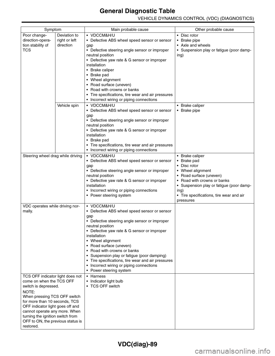
General Diagnostic Table
VEHICLE DYNAMICS CONTROL (VDC) (DIAGNOSTICS)
Po or ch a ng e -
direction-opera-
tion stability of
TCS
Deviation to
right or left
direction
•VDCCM&H/U
•Defective ABS wheel speed sensor or sensor
gap
•Defective steering angle sensor or improper
neutral position
•Defective yaw rate & G sensor or improper
installation
•Brake caliper
•Brake pad
•Wheel alignment
•Road surface (uneven)
•Road with crowns or banks
•Tire specifications, tire wear and air pressures
•Incorrect wiring or piping connections
•Disc rotor
•Brake pipe
•Axle and wheels
•Suspension play or fatigue (poor damp-
ing)
Ve h i c l e s p i n • V D C C M & H / U
•Defective ABS wheel speed sensor or sensor
gap
•Defective steering angle sensor or improper
neutral position
•Defective yaw rate & G sensor or improper
installation
•Brake pad
•Tire specifications, tire wear and air pressures
•Incorrect wiring or piping connections
•Brake caliper
•Brake pipe
Steering wheel drag while driving • VDCCM&H/U
•Defective ABS wheel speed sensor or sensor
gap
•Defective steering angle sensor or improper
neutral position
•Defective yaw rate & G sensor or improper
installation
•Incorrect wiring or piping connections
•Power steering system
•Brake caliper
•Brake pad
•Disc rotor
•Wheel alignment
•Road surface (uneven)
•Road with crowns or banks
•Suspension play or fatigue (poor damp-
ing)
•Tire specifications, tire wear and air
pressures
VDC operates while driving nor-
mally.
•VDCCM&H/U
•Defective ABS wheel speed sensor or sensor
gap
•Defective steering angle sensor or improper
neutral position
•Defective yaw rate & G sensor or improper
installation
•Wheel alignment
•Road surface (uneven)
•Road with crowns or banks
•Suspension play or fatigue (poor damping)
•Tire specifications, tire wear and air pressures
•Incorrect wiring or piping connections
•Power steering system
TCS OFF indicator light does not
come on when the TCS OFF
switch is depressed.
NOTE:When pressing TCS OFF switch
for more than 10 seconds, TCS
OFF indicator light goes off and
cannot operate any more. When
turning the ignition switch from
OFF to ON, the previous status is
restored.
•Harness
•Indicator light bulb
•TCS OFF switch
Symptom Main probable cause Other probable cause
Page 1092 of 2453
VDC-11
VDC Control Module & Hydraulic Control Unit (VDCCM&H/U)
VEHICLE DYNAMICS CONTROL (VDC)
D: ADJUSTMENT
When the following replacement, removal and in-
stallation are performed, be sure to perform center-
ing of the steering angle sensor and zero point
setting of the yaw rate & G sensor.
•VDCCM&H/U
•Steering angle sensor
•Yaw rate & lateral G sensor
•Steering wheel parts (Including airbag)
•Suspension parts
•Wheel alignment adjustment
1) Park the vehicle straight on a level surface. (En-
gine operation in the “P” or “N” range)
2) Check that steering wheel is positioned at the
center. (When the center position is not correct, ad-
just the wheel alignment.)
3) Set the Subaru Select Monitor to the vehicle,
and select {Set up mode for Neutral of Steering An-
gle Sensor & Lateral G Sensor 0 point} in the
“Function check sequence” screen. (Follow the
procedures shown in the display.)
4) On the “Brake Control System” display screen,
select {Current Data Display & Save}, and check
that the steering angle sensor shows “0 deg”.
5) When the “0 deg” is not displayed, repeat the
above steps and check that the “0 deg” is dis-
played.
6) Drive the vehicle for 10 minutes, and check that
the ABS and VDC warning light is not illuminated.
7) Check that there is no unnecessary VDC opera-
tion or steering control loss. If there is a problem,
repeat the steps above.
Page 1102 of 2453
VDC-21
Front ABS Wheel Speed Sensor
VEHICLE DYNAMICS CONTROL (VDC)
7. Front ABS Wheel Speed Sen-
sor
A: REMOVAL
1) Disconnect the ground cable from the battery.
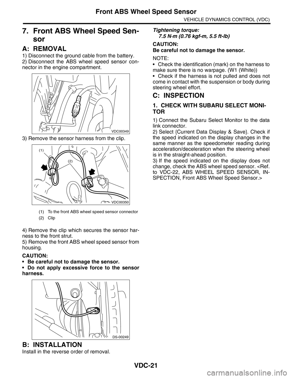
2) Disconnect the ABS wheel speed sensor con-
nector in the engine compartment.
3) Remove the sensor harness from the clip.
4) Remove the clip which secures the sensor har-
ness to the front strut.
5) Remove the front ABS wheel speed sensor from
housing.
CAUTION:
•Be careful not to damage the sensor.
•Do not apply excessive force to the sensor
harness.
B: INSTALLATION
Install in the reverse order of removal.
Tightening torque:
7.5 N·m (0.76 kgf-m, 5.5 ft-lb)
CAUTION:
Be careful not to damage the sensor.
NOTE:
•Check the identification (mark) on the harness to
make sure there is no warpage. (W1 (White))
•Check if the harness is not pulled and does not
come in contact with the suspension or body during
steering wheel effort.
C: INSPECTION
1. CHECK WITH SUBARU SELECT MONI-
TOR
1) Connect the Subaru Select Monitor to the data
link connector.
2) Select {Current Data Display & Save}. Check if
the speed indicated on the display changes in the
same manner as the speedometer reading during
acceleration/deceleration when the steering wheel
is in the straight-ahead position.
3) If the speed indicated on the display does not
change, check the ABS wheel speed sensor.
SPECTION, Front ABS Wheel Speed Sensor.>
(1) To the front ABS wheel speed sensor connector
(2) Clip
VDC00349
VDC00350
(1)
(2)
DS-00249
Page 1153 of 2453
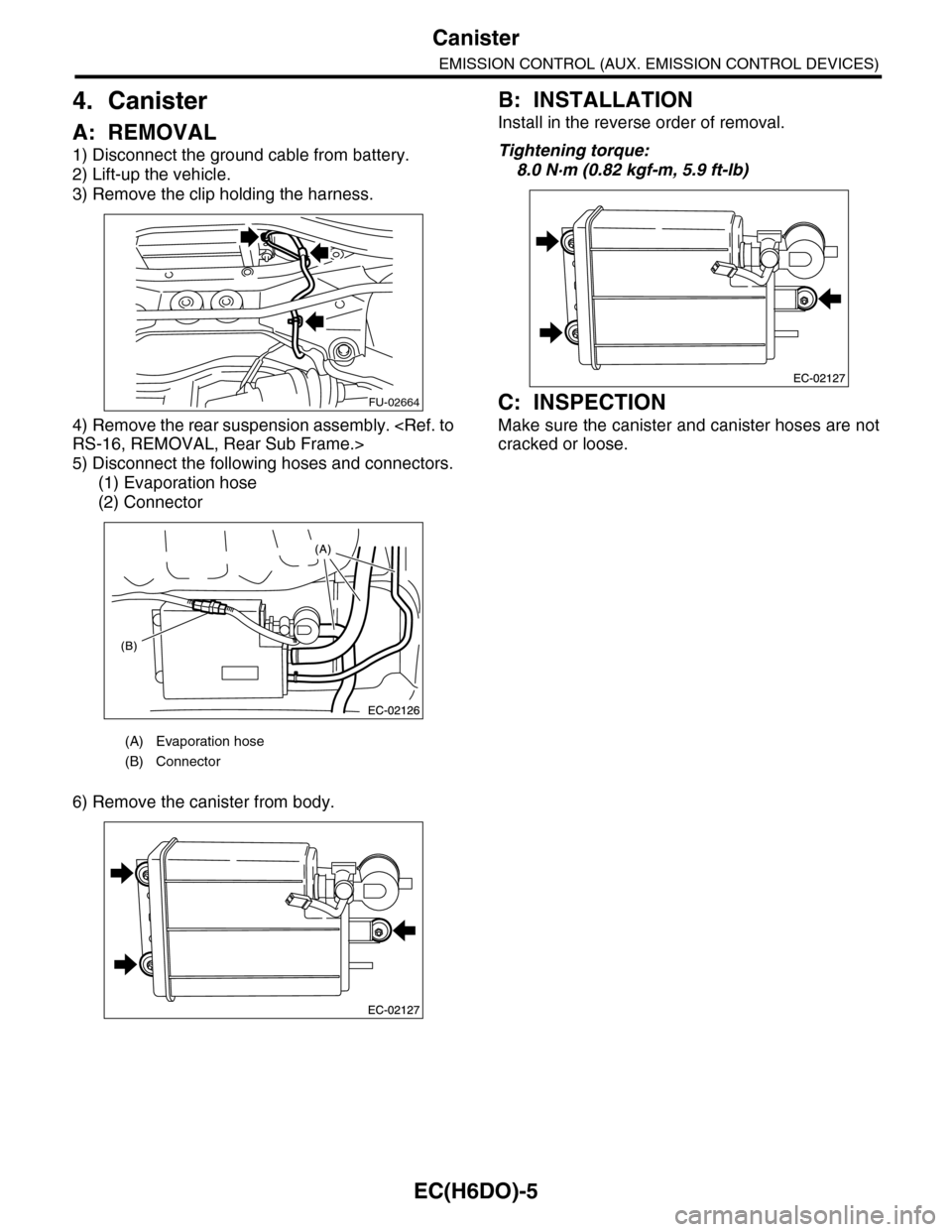
EC(H6DO)-5
Canister
EMISSION CONTROL (AUX. EMISSION CONTROL DEVICES)
4. Canister
A: REMOVAL
1) Disconnect the ground cable from battery.
2) Lift-up the vehicle.
3) Remove the clip holding the harness.
4) Remove the rear suspension assembly.
5) Disconnect the following hoses and connectors.
(1) Evaporation hose
(2) Connector
6) Remove the canister from body.
B: INSTALLATION
Install in the reverse order of removal.
Tightening torque:
8.0 N·m (0.82 kgf-m, 5.9 ft-lb)
C: INSPECTION
Make sure the canister and canister hoses are not
cracked or loose.
(A) Evaporation hose
(B) Connector
FU-02664
Page 1599 of 2453
FU(H6DO)-38
Fuel Tank
FUEL INJECTION (FUEL SYSTEMS)
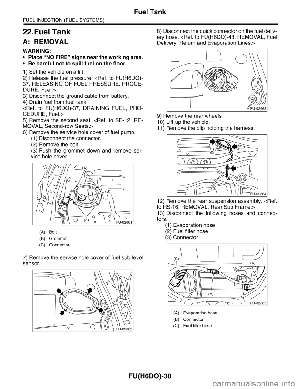
22.Fuel Tank
A: REMOVAL
WARNING:
•Place “NO FIRE” signs near the working area.
•Be careful not to spill fuel on the floor.
1) Set the vehicle on a lift.
2) Release the fuel pressure.
DURE, Fuel.>
3) Disconnect the ground cable from battery.
4) Drain fuel from fuel tank.
5) Remove the second seat.
6) Remove the service hole cover of fuel pump.
(1) Disconnect the connector.
(2) Remove the bolt.
(3) Push the grommet down and remove ser-
vice hole cover.
7) Remove the service hole cover of fuel sub level
sensor.
8) Disconnect the quick connector on the fuel deliv-
ery hose.
9) Remove the rear wheels.
10) Lift-up the vehicle.
11) Remove the clip holding the harness.
12) Remove the rear suspension assembly.
13) Disconnect the following hoses and connec-
tors.
(1) Evaporation hose
(2) Fuel filler hose
(3) Connector
(A) Bolt
(B) Grommet
(C) Connector
FU-02661(A)
(A)
(B)(C)
FU-02662
(A) Evaporation hose
(B) Connector
(C) Fuel filler hose
FU-02663
FU-02664
FU-02665
(A)
(B)
(C)
Page 1600 of 2453
FU(H6DO)-39
Fuel Tank
FUEL INJECTION (FUEL SYSTEMS)
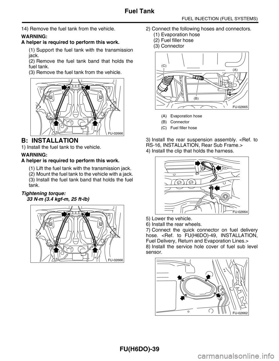
14) Remove the fuel tank from the vehicle.
WARNING:
A helper is required to perform this work.
(1) Support the fuel tank with the transmission
jack.
(2) Remove the fuel tank band that holds the
fuel tank.
(3) Remove the fuel tank from the vehicle.
B: INSTALLATION
1) Install the fuel tank to the vehicle.
WARNING:
A helper is required to perform this work.
(1) Lift the fuel tank with the transmission jack.
(2) Mount the fuel tank to the vehicle with a jack.
(3) Install the fuel tank band that holds the fuel
tank.
Tightening torque:
33 N·m (3.4 kgf-m, 25 ft-lb)
2) Connect the following hoses and connectors.
(1) Evaporation hose
(2) Fuel filler hose
(3) Connector
3) Install the rear suspension assembly.
4) Install the clip that holds the harness.
5) Lower the vehicle.
6) Install the rear wheels.
7) Connect the quick connector on fuel delivery
hose.
8) Install the service hole cover of fuel sub level
sensor.
FU-02666
FU-02666
(A) Evaporation hose
(B) Connector
(C) Fuel filler hose
FU-02665
(A)
(B)
(C)
FU-02664
FU-02662
Page 1602 of 2453
FU(H6DO)-41
Fuel Filler Pipe
FUEL INJECTION (FUEL SYSTEMS)
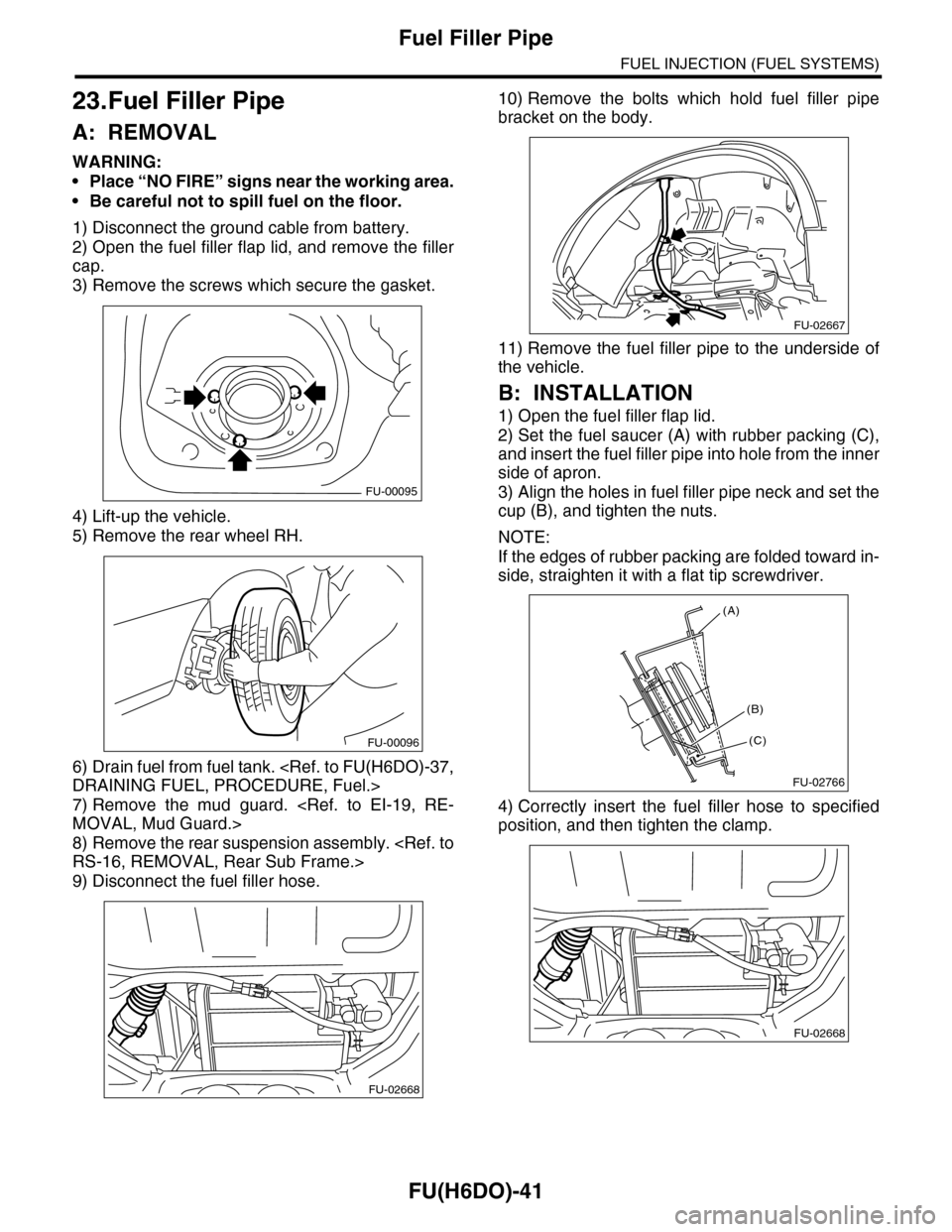
23.Fuel Filler Pipe
A: REMOVAL
WARNING:
•Place “NO FIRE” signs near the working area.
•Be careful not to spill fuel on the floor.
1) Disconnect the ground cable from battery.
2) Open the fuel filler flap lid, and remove the filler
cap.
3) Remove the screws which secure the gasket.
4) Lift-up the vehicle.
5) Remove the rear wheel RH.
6) Drain fuel from fuel tank.
7) Remove the mud guard.
8) Remove the rear suspension assembly.
9) Disconnect the fuel filler hose.
10) Remove the bolts which hold fuel filler pipe
bracket on the body.
11) Remove the fuel filler pipe to the underside of
the vehicle.
B: INSTALLATION
1) Open the fuel filler flap lid.
2) Set the fuel saucer (A) with rubber packing (C),
and insert the fuel filler pipe into hole from the inner
side of apron.
3) Align the holes in fuel filler pipe neck and set the
cup (B), and tighten the nuts.
NOTE:
If the edges of rubber packing are folded toward in-
side, straighten it with a flat tip screwdriver.
4) Correctly insert the fuel filler hose to specified
position, and then tighten the clamp.
FU-00095
FU-00096
FU-02668
FU-02667
FU-02766
(A)
(C)
(B)
FU-02668