2009 SUBARU TRIBECA ecm
[x] Cancel search: ecmPage 2131 of 2453
5AT(diag)-14
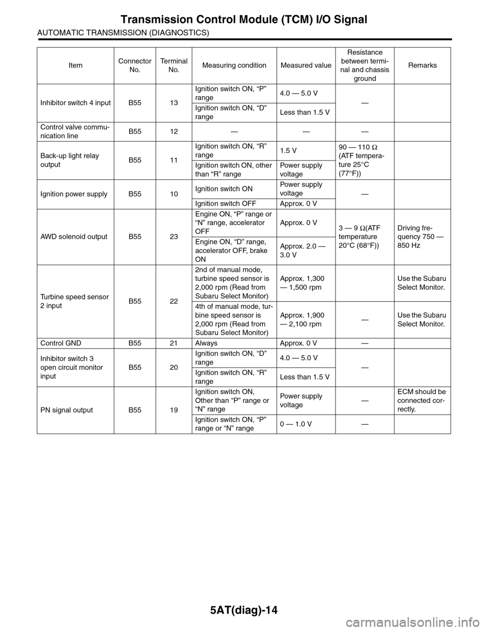
Transmission Control Module (TCM) I/O Signal
AUTOMATIC TRANSMISSION (DIAGNOSTICS)
Inhibitor switch 4 input B55 13
Ignition switch ON, “P”
range4.0 — 5.0 V
—
Ignition switch ON, “D”
rangeLess than 1.5 V
Control valve commu-
nication lineB55 12 — — —
Back-up light relay
outputB55 11
Ignition switch ON, “R”
range1.5 V90 — 110 Ω
(ATF tempera-
ture 25°C
(77°F))
Ignition switch ON, other
than “R” range
Pow er s up p ly
voltage
Ignition power supply B55 10Ignition switch ONPow er s up p ly
voltage—
Ignition switch OFF Approx. 0 V
AW D s o le n oi d o u tp u t B 5 5 2 3
Engine ON, “P” range or
“N” range, accelerator
OFF
Approx. 0 V3 — 9 Ω(ATF
temperature
20°C (68°F))
Driving fre-
quency 750 —
850 HzEngine ON, “D” range,
accelerator OFF, brake
ON
Approx. 2.0 —
3.0 V
Tu r b i n e s p e e d s e n s o r
2 inputB55 22
2nd of manual mode,
turbine speed sensor is
2,000 rpm (Read from
Subaru Select Monitor)
Approx. 1,300
— 1,500 rpm
Use the Subaru
Select Monitor.
4th of manual mode, tur-
bine speed sensor is
2,000 rpm (Read from
Subaru Select Monitor)
Approx. 1,900
— 2,100 rpm—Use the Subaru
Select Monitor.
Control GND B55 21 Always Approx. 0 V —
Inhibitor switch 3
open circuit monitor
input
B55 20
Ignition switch ON, “D”
range4.0 — 5.0 V
—
Ignition switch ON, “R”
rangeLess than 1.5 V
PN signal output B55 19
Ignition switch ON,
Other than “P” range or
“N” range
Pow er s up p ly
voltage—
ECM should be
connected cor-
rectly.
Ignition switch ON, “P”
range or “N” range0 — 1.0 V —
ItemConnector
No.
Te r m i n a l
No.Measuring condition Measured value
Resistance
between termi-
nal and chassis
ground
Remarks
Page 2143 of 2453
5AT(diag)-26
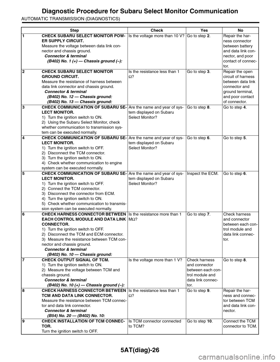
Diagnostic Procedure for Subaru Select Monitor Communication
AUTOMATIC TRANSMISSION (DIAGNOSTICS)
Step Check Yes No
1CHECK SUBARU SELECT MONITOR POW-
ER SUPPLY CIRCUIT.
Measure the voltage between data link con-
nector and chassis ground.
Connector & terminal
(B402) No. 1 (+) — Chassis ground (–):
Is the voltage more than 10 V? Go to step 2.Repair the har-
ness connector
between battery
and data link con-
nector, and poor
contact of connec-
tor.
2CHECK SUBARU SELECT MONITOR
GROUND CIRCUIT.
Measure the resistance of harness between
data link connector and chassis ground.
Connector & terminal
(B402) No. 12 — Chassis ground:
(B402) No. 13 — Chassis ground:
Is the resistance less than 1
Ω?
Go to step 3.Repair the open
circuit of harness
between data link
connector and
ground terminal,
and poor contact
of connector.
3CHECK COMMUNICATION OF SUBARU SE-
LECT MONITOR.
1) Turn the ignition switch to ON.
2) Using the Subaru Select Monitor, check
whether communication to transmission sys-
tem can be executed normally.
Are the name and year of sys-
tem displayed on Subaru
Select Monitor?
Go to step 8.Go to step 4.
4CHECK COMMUNICATION OF SUBARU SE-
LECT MONITOR.
1) Turn the ignition switch to OFF.
2) Disconnect the TCM connector.
3) Turn the ignition switch to ON.
4) Check whether communication to engine
system can be executed normally.
Are the name and year of sys-
tem displayed on Subaru
Select Monitor?
Go to step 6.Go to step 5.
5CHECK COMMUNICATION OF SUBARU SE-
LECT MONITOR.
1) Turn the ignition switch to OFF.
2) Connect the TCM connector.
3) Disconnect the connector from ECM.
4) Turn the ignition switch to ON.
5) Check whether communication to transmis-
sion system can be executed normally.
Are the name and year of sys-
tem displayed on Subaru
Select Monitor?
Inspect the ECM. Go to step 6.
6CHECK HARNESS CONNECTOR BETWEEN
EACH CONTROL MODULE AND DATA LINK
CONNECTOR.
1) Turn the ignition switch to OFF.
2) Disconnect the TCM and ECM connector.
3) Measure the resistance between TCM con-
nector and chassis ground.
Connector & terminal
(B402) No. 10 — Chassis ground:
Is the resistance more than 1
MΩ?
Go to step 7.Check harness
and connector
between each con-
trol module and
data link connec-
tor.
7CHECK OUTPUT SIGNAL OF TCM.
1) Turn the ignition switch to ON.
2) Measure the voltage between TCM and
chassis ground.
Connector & terminal
(B402) No. 10 (+) — Chassis ground (–):
Is the voltage more than 1 V? Check harness
and connector
between each con-
trol module and
data link connec-
tor.
Go to step 8.
8CHECK HARNESS CONNECTOR BETWEEN
TCM AND DATA LINK CONNECTOR.
Measure the resistance between TCM connec-
tor and data link connector.
Connector & terminal
(B54) No. 20 — (B402) No. 10:
Is the resistance less than 1
Ω?
Go to step 9.Repair the har-
ness and connec-
tor between TCM
and data link con-
nector.
9CHECK INSTALLATION OF TCM CONNEC-
TOR.
Tu r n t h e i g n i t i o n s w i t c h t o O F F.
Is TCM connector connected
to TCM?
Go to step 10.Connect the TCM
connector to TCM.
Page 2145 of 2453
5AT(diag)-28
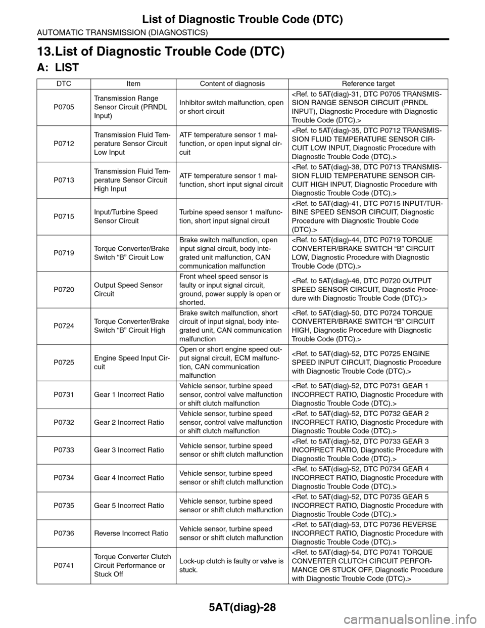
List of Diagnostic Trouble Code (DTC)
AUTOMATIC TRANSMISSION (DIAGNOSTICS)
13.List of Diagnostic Trouble Code (DTC)
A: LIST
DTC Item Content of diagnosis Reference target
P0705
Tr a n s m i s s i o n R a n g e
Sensor Circuit (PRNDL
Input)
Inhibitor switch malfunction, open
or short circuit
INPUT), Diagnostic Procedure with Diagnostic
Tr o u b l e C o d e ( D T C ) . >
P0712
Tr a n s m i s s i o n F l u i d Te m -
perature Sensor Circuit
Low Input
AT F t e m p e r a t u r e s e n s o r 1 m a l -
function, or open input signal cir-
cuit
CUIT LOW INPUT, Diagnostic Procedure with
Diagnostic Trouble Code (DTC).>
P0713
Tr a n s m i s s i o n F l u i d Te m -
perature Sensor Circuit
High Input
AT F t e m p e r a t u r e s e n s o r 1 m a l -
function, short input signal circuit
CUIT HIGH INPUT, Diagnostic Procedure with
Diagnostic Trouble Code (DTC).>
P0715Input/Turbine Speed
Sensor Circuit
Tu r b i n e s p e e d s e n s o r 1 m a l f u n c -
tion, short input signal circuit
Procedure with Diagnostic Trouble Code
(DTC).>
P0719To r q u e C o n v e r t e r / B r a k e
Switch “B” Circuit Low
Brake switch malfunction, open
input signal circuit, body inte-
grated unit malfunction, CAN
communication malfunction
LOW, Diagnostic Procedure with Diagnostic
Tr o u b l e C o d e ( D T C ) . >
P0720Output Speed Sensor
Circuit
Front wheel speed sensor is
faulty or input signal circuit,
ground, power supply is open or
shorted.
dure with Diagnostic Trouble Code (DTC).>
P0724To r q u e C o n v e r t e r / B r a k e
Switch “B” Circuit High
Brake switch malfunction, short
circuit of input signal, body inte-
grated unit, CAN communication
malfunction
HIGH, Diagnostic Procedure with Diagnostic
Tr o u b l e C o d e ( D T C ) . >
P0725Engine Speed Input Cir-
cuit
Open or short engine speed out-
put signal circuit, ECM malfunc-
tion, CAN communication
malfunction
with Diagnostic Trouble Code (DTC).>
P0731 Gear 1 Incorrect Ratio
Ve h i c l e s e n s o r, t u r b i n e s p e e d
sensor, control valve malfunction
or shift clutch malfunction
Diagnostic Trouble Code (DTC).>
P0732 Gear 2 Incorrect Ratio
Ve h i c l e s e n s o r, t u r b i n e s p e e d
sensor, control valve malfunction
or shift clutch malfunction
Diagnostic Trouble Code (DTC).>
P0733 Gear 3 Incorrect RatioVe h i c l e s e n s o r, t u r b i n e s p e e d
sensor or shift clutch malfunction
Diagnostic Trouble Code (DTC).>
P0734 Gear 4 Incorrect RatioVe h i c l e s e n s o r, t u r b i n e s p e e d
sensor or shift clutch malfunction
Diagnostic Trouble Code (DTC).>
P0735 Gear 5 Incorrect RatioVe h i c l e s e n s o r, t u r b i n e s p e e d
sensor or shift clutch malfunction
Diagnostic Trouble Code (DTC).>
P0736 Reverse Incorrect RatioVe h i c l e s e n s o r, t u r b i n e s p e e d
sensor or shift clutch malfunction
Diagnostic Trouble Code (DTC).>
P0741
To r q u e C o n v e r t e r C l u t c h
Circuit Performance or
Stuck Off
Lock-up clutch is faulty or valve is
stuck.
MANCE OR STUCK OFF, Diagnostic Procedure
with Diagnostic Trouble Code (DTC).>
Page 2146 of 2453
5AT(diag)-29
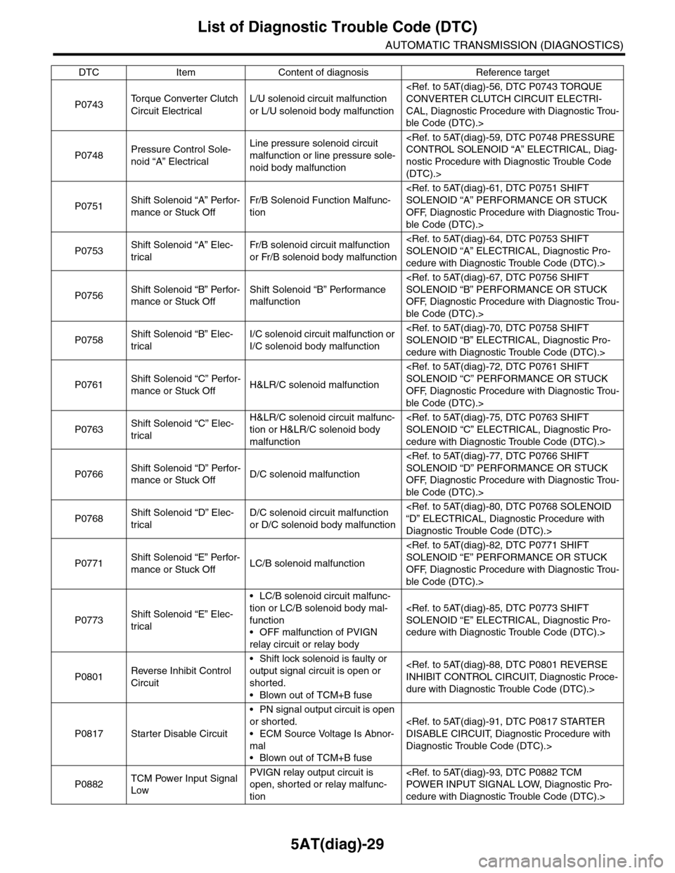
List of Diagnostic Trouble Code (DTC)
AUTOMATIC TRANSMISSION (DIAGNOSTICS)
P0743To r q u e C o n v e r t e r C l u t c h
Circuit Electrical
L/U solenoid circuit malfunction
or L/U solenoid body malfunction
CAL, Diagnostic Procedure with Diagnostic Trou-
ble Code (DTC).>
P0748Pressure Control Sole-
noid “A” Electrical
Line pressure solenoid circuit
malfunction or line pressure sole-
noid body malfunction
nostic Procedure with Diagnostic Trouble Code
(DTC).>
P0751Shift Solenoid “A” Perfor-
mance or Stuck Off
Fr/B Solenoid Function Malfunc-
tion
OFF, Diagnostic Procedure with Diagnostic Trou-
ble Code (DTC).>
P0753Shift Solenoid “A” Elec-
trical
Fr/B solenoid circuit malfunction
or Fr/B solenoid body malfunction
cedure with Diagnostic Trouble Code (DTC).>
P0756Shift Solenoid “B” Perfor-
mance or Stuck Off
Shift Solenoid “B” Performance
malfunction
OFF, Diagnostic Procedure with Diagnostic Trou-
ble Code (DTC).>
P0758Shift Solenoid “B” Elec-
trical
I/C solenoid circuit malfunction or
I/C solenoid body malfunction
cedure with Diagnostic Trouble Code (DTC).>
P0761Shift Solenoid “C” Perfor-
mance or Stuck OffH&LR/C solenoid malfunction
OFF, Diagnostic Procedure with Diagnostic Trou-
ble Code (DTC).>
P0763Shift Solenoid “C” Elec-
trical
H&LR/C solenoid circuit malfunc-
tion or H&LR/C solenoid body
malfunction
cedure with Diagnostic Trouble Code (DTC).>
P0766Shift Solenoid “D” Perfor-
mance or Stuck OffD/C solenoid malfunction
OFF, Diagnostic Procedure with Diagnostic Trou-
ble Code (DTC).>
P0768Shift Solenoid “D” Elec-
trical
D/C solenoid circuit malfunction
or D/C solenoid body malfunction
Diagnostic Trouble Code (DTC).>
P0771Shift Solenoid “E” Perfor-
mance or Stuck OffLC/B solenoid malfunction
OFF, Diagnostic Procedure with Diagnostic Trou-
ble Code (DTC).>
P0773Shift Solenoid “E” Elec-
trical
•LC/B solenoid circuit malfunc-
tion or LC/B solenoid body mal-
function
•OFF malfunction of PVIGN
relay circuit or relay body
cedure with Diagnostic Trouble Code (DTC).>
P0801Reverse Inhibit Control
Circuit
•Shift lock solenoid is faulty or
output signal circuit is open or
shorted.
•Blown out of TCM+B fuse
dure with Diagnostic Trouble Code (DTC).>
P0817 Starter Disable Circuit
•PN signal output circuit is open
or shorted.
•ECM Source Voltage Is Abnor-
mal
•Blown out of TCM+B fuse
Diagnostic Trouble Code (DTC).>
P0882TCM Power Input Signal
Low
PVIGN relay output circuit is
open, shorted or relay malfunc-
tion
cedure with Diagnostic Trouble Code (DTC).>
DTC Item Content of diagnosis Reference target
Page 2169 of 2453
5AT(diag)-52
Diagnostic Procedure with Diagnostic Trouble Code (DTC)
AUTOMATIC TRANSMISSION (DIAGNOSTICS)
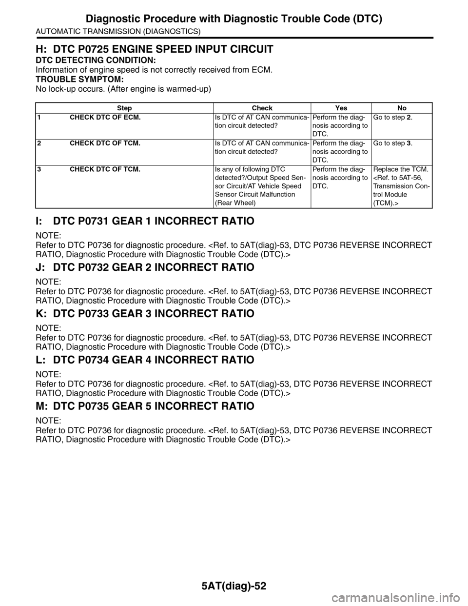
H: DTC P0725 ENGINE SPEED INPUT CIRCUIT
DTC DETECTING CONDITION:
Information of engine speed is not correctly received from ECM.
TROUBLE SYMPTOM:
No lock-up occurs. (After engine is warmed-up)
I: DTC P0731 GEAR 1 INCORRECT RATIO
NOTE:
Refer to DTC P0736 for diagnostic procedure.
J: DTC P0732 GEAR 2 INCORRECT RATIO
NOTE:
Refer to DTC P0736 for diagnostic procedure.
K: DTC P0733 GEAR 3 INCORRECT RATIO
NOTE:
Refer to DTC P0736 for diagnostic procedure.
L: DTC P0734 GEAR 4 INCORRECT RATIO
NOTE:
Refer to DTC P0736 for diagnostic procedure.
M: DTC P0735 GEAR 5 INCORRECT RATIO
NOTE:
Refer to DTC P0736 for diagnostic procedure.
Step Check Yes No
1CHECK DTC OF ECM.Is DTC of AT CAN communica-
tion circuit detected?
Pe r for m t h e d ia g -
nosis according to
DTC.
Go to step 2.
2CHECK DTC OF TCM.Is DTC of AT CAN communica-
tion circuit detected?
Pe r for m t h e d ia g -
nosis according to
DTC.
Go to step 3.
3CHECK DTC OF TCM.Is any of following DTC
detected?/Output Speed Sen-
sor Circuit/AT Vehicle Speed
Sensor Circuit Malfunction
(Rear Wheel)
Pe r for m t h e d ia g -
nosis according to
DTC.
Replace the TCM.
trol Module
(TCM).>
Page 2208 of 2453
5AT(diag)-91
Diagnostic Procedure with Diagnostic Trouble Code (DTC)
AUTOMATIC TRANSMISSION (DIAGNOSTICS)
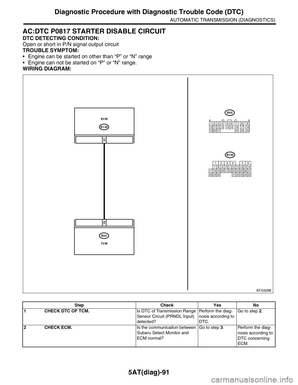
AC:DTC P0817 STARTER DISABLE CIRCUIT
DTC DETECTING CONDITION:
Open or short in P/N signal output circuit
TROUBLE SYMPTOM:
•Engine can be started on other than “P” or “N” range
•Engine can not be started on “P” or “N” range.
WIRING DIAGRAM:
AT-03288
B136
B55
31
19
ECM
TCM
B55
12341011 121920 21135614 1578916 17 1822 23 24
B136
16101112131415252430
9871718192028212223293231
123456
2726333435
Step Check Yes No
1CHECK DTC OF TCM.Is DTC of Transmission Range
Sensor Circuit (PRNDL Input)
detected?
Pe r for m t h e d ia g -
nosis according to
DTC.
Go to step 2.
2CHECK ECM.Is the communication between
Subaru Select Monitor and
ECM normal?
Go to step 3.Perform the diag-
nosis according to
DTC concerning
ECM.
Page 2209 of 2453
5AT(diag)-92
Diagnostic Procedure with Diagnostic Trouble Code (DTC)
AUTOMATIC TRANSMISSION (DIAGNOSTICS)
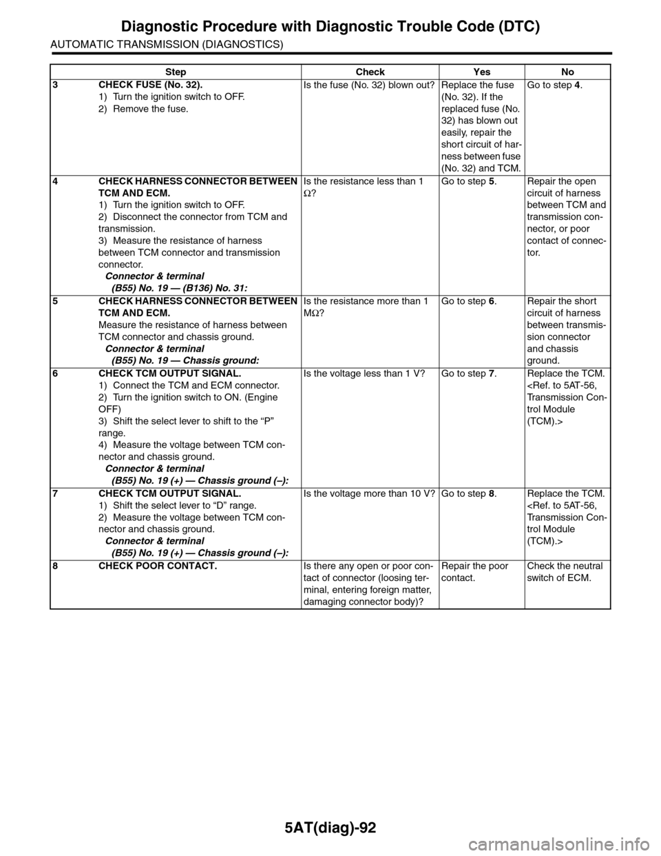
3CHECK FUSE (No. 32).
1) Turn the ignition switch to OFF.
2) Remove the fuse.
Is the fuse (No. 32) blown out? Replace the fuse
(No. 32). If the
replaced fuse (No.
32) has blown out
easily, repair the
short circuit of har-
ness between fuse
(No. 32) and TCM.
Go to step 4.
4CHECK HARNESS CONNECTOR BETWEEN
TCM AND ECM.
1) Turn the ignition switch to OFF.
2) Disconnect the connector from TCM and
transmission.
3) Measure the resistance of harness
between TCM connector and transmission
connector.
Connector & terminal
(B55) No. 19 — (B136) No. 31:
Is the resistance less than 1
Ω?
Go to step 5.Repair the open
circuit of harness
between TCM and
transmission con-
nector, or poor
contact of connec-
tor.
5CHECK HARNESS CONNECTOR BETWEEN
TCM AND ECM.
Measure the resistance of harness between
TCM connector and chassis ground.
Connector & terminal
(B55) No. 19 — Chassis ground:
Is the resistance more than 1
MΩ?
Go to step 6.Repair the short
circuit of harness
between transmis-
sion connector
and chassis
ground.
6CHECK TCM OUTPUT SIGNAL.
1) Connect the TCM and ECM connector.
2) Turn the ignition switch to ON. (Engine
OFF)
3) Shift the select lever to shift to the “P”
range.
4) Measure the voltage between TCM con-
nector and chassis ground.
Connector & terminal
(B55) No. 19 (+) — Chassis ground (–):
Is the voltage less than 1 V? Go to step 7.Replace the TCM.
trol Module
(TCM).>
7CHECK TCM OUTPUT SIGNAL.
1) Shift the select lever to “D” range.
2) Measure the voltage between TCM con-
nector and chassis ground.
Connector & terminal
(B55) No. 19 (+) — Chassis ground (–):
Is the voltage more than 10 V? Go to step 8.Replace the TCM.
trol Module
(TCM).>
8CHECK POOR CONTACT.Is there any open or poor con-
tact of connector (loosing ter-
minal, entering foreign matter,
damaging connector body)?
Repair the poor
contact.
Check the neutral
switch of ECM.
Step Check Yes No
Page 2297 of 2453
WI-13
Basic Diagnostic Procedure
WIRING SYSTEM
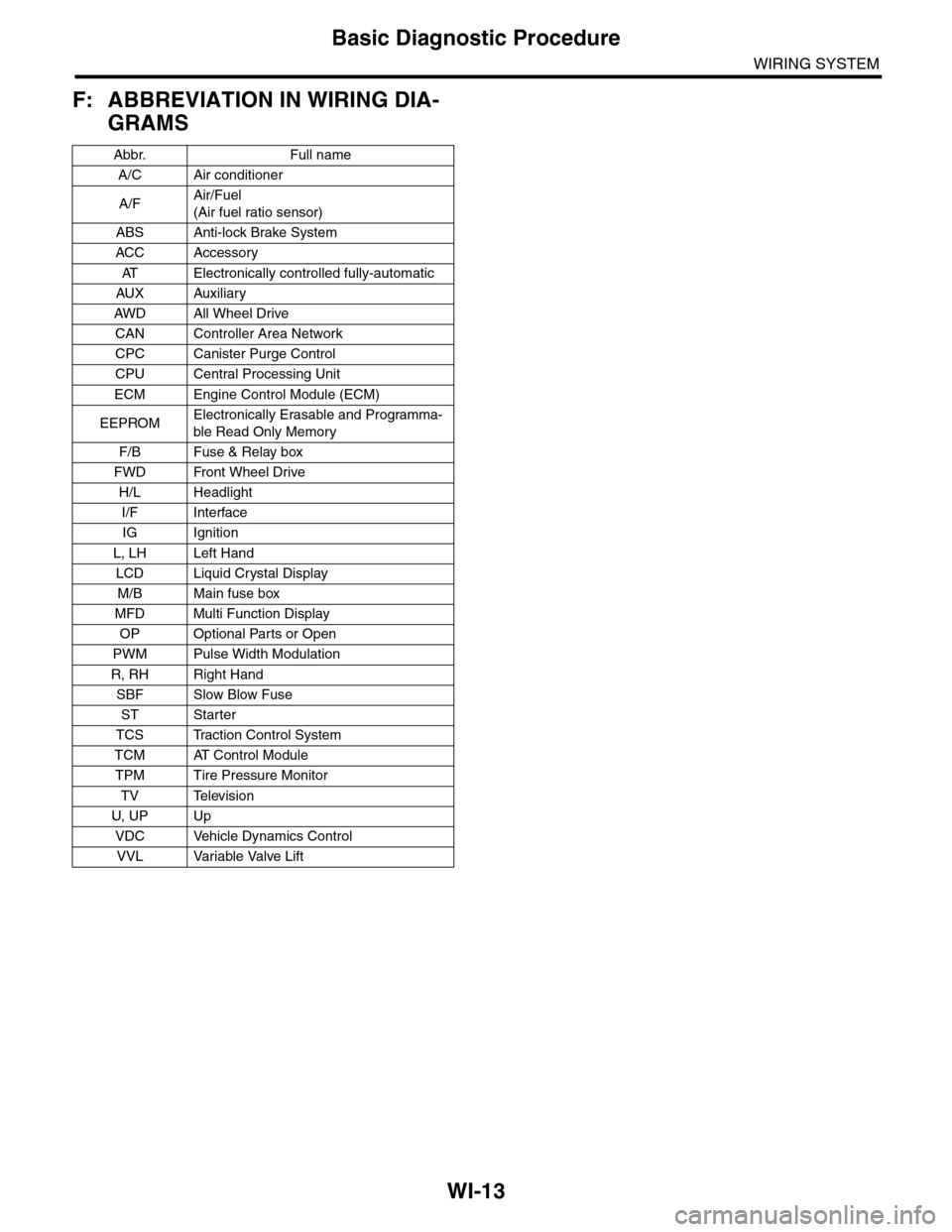
F: ABBREVIATION IN WIRING DIA-
GRAMS
Abbr. Full name
A/C Air conditioner
A/FAir/Fuel
(Air fuel ratio sensor)
ABS Anti-lock Brake System
ACC Accessor y
AT E l e c t r o n i c a l l y c o n t r o l l e d f u l l y - a u t o m a t i c
AUX Auxiliar y
AW D A ll W he e l D r i ve
CAN Controller Area Network
CPC Canister Purge Control
CPU Central Processing Unit
ECM Engine Control Module (ECM)
EEPROMElectronically Erasable and Programma-
ble Read Only Memory
F/B Fuse & Relay box
FWD Front Wheel Drive
H/L Headlight
I/F Interface
IG Ignition
L, LH Left Hand
LCD Liquid Crystal Display
M/B Main fuse box
MFD Multi Function Display
OP Optional Parts or Open
PWM Pulse Width Modulation
R, RH Right Hand
SBF Slow Blow Fuse
ST Starter
TCS Traction Control System
TCM AT Control Module
TPM Tire Pressure Monitor
TV Television
U, UP Up
VDC Vehicle Dynamics Control
VVL Variable Valve Lift