Page 1831 of 2453
GD(H6DO)-219
Diagnostic Trouble Code (DTC) Detecting Criteria
GENERAL DESCRIPTION
EL:DTC P2138 THROTTLE/PEDAL POSITION SENSOR/ SWITCH “D”/“E” VOLT-
AGE RATIONALITY
1. OUTLINE OF DIAGNOSIS
Judge as NG when the signal level of throttle position sensor 1 is different from the throttle position sensor 2.
2. COMPONENT DESCRIPTION
3. ENABLE CONDITIONS
4. GENERAL DRIVING CYCLE
Always perform the diagnosis continuously.
5. DIAGNOSTIC METHOD
Judge as OK and clear the NG when the malfunction criteria below are met.
(1) Engine control module (ECM) (3)
Accelerator pedal position sensor
2 signal.
(4) Accelerator pedal position sensor
(2) Accelerator pedal position sensor
1 signal
Secondary Parameters Enable Conditions
Ignition switch ON
Judgment Value
Malfunction Criteria Threshold Value
Signal difference between two sensors≤ 0.634°
EN-01861
(2)
(3)
(4)(1)
Page 1832 of 2453
GD(H6DO)-220
Diagnostic Trouble Code (DTC) Detecting Criteria
GENERAL DESCRIPTION
Details of Judgment Value
Time Needed for Diagnosis:
•116 milliseconds (For NG)
•1000 milliseconds (For OK)
Malfunction Indicator Light: Illuminates as soon as a malfunction occurs.
6. DTC CLEAR CONDITION
•When the OK idling cycle is completed 40 times in a row
•When “Clear Memory” is performed
7. MALFUNCTION INDICATOR LIGHT CLEAR CONDITIONS
•When the OK driving cycle is completed 3 times in a row
•When “Clear Memory” is performed
8. FAIL SAFE
Throttle opening is fixed to 6.375°.
9. ECM OPERATION AT DTC SETTING
Memorize the freeze frame data. (For test mode $02)
(1) Sensor output difference (°) (2) Throttle position sensor 2 open-
ing angle (°)
(3) NG area
EN-03851
0
(0.916)
(0.634)
(1.297)
(1)
(3)
0(0.6)
(2)
(1.2)(4.0)(2.0)
(2.492)
(1.947)
Page 1833 of 2453
GD(H6DO)-221
Diagnostic Trouble Code (DTC) Detecting Criteria
GENERAL DESCRIPTION
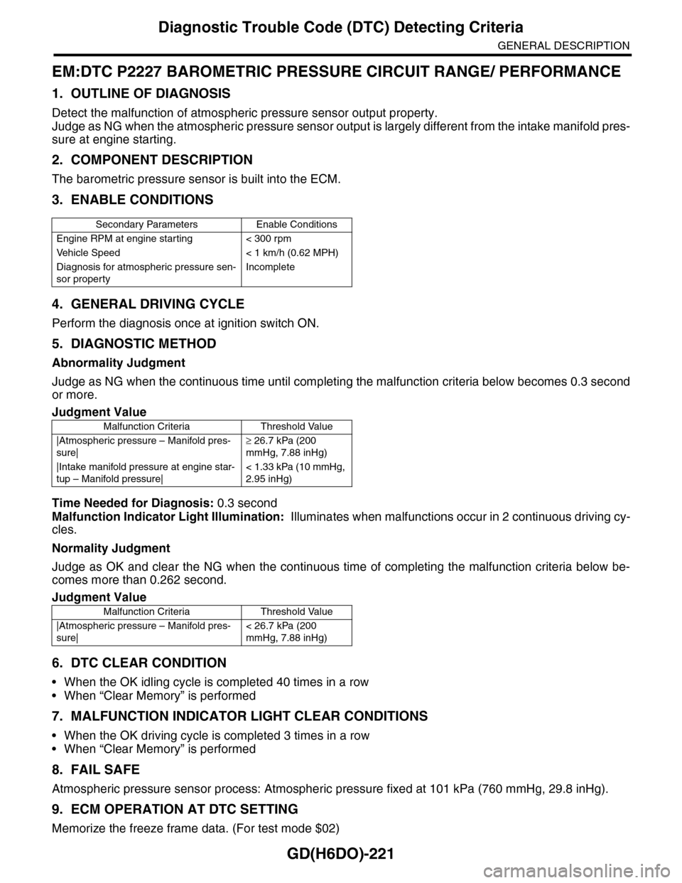
EM:DTC P2227 BAROMETRIC PRESSURE CIRCUIT RANGE/ PERFORMANCE
1. OUTLINE OF DIAGNOSIS
Detect the malfunction of atmospheric pressure sensor output property.
Judge as NG when the atmospheric pressure sensor output is largely different from the intake manifold pres-
sure at engine starting.
2. COMPONENT DESCRIPTION
The barometric pressure sensor is built into the ECM.
3. ENABLE CONDITIONS
4. GENERAL DRIVING CYCLE
Perform the diagnosis once at ignition switch ON.
5. DIAGNOSTIC METHOD
Abnormality Judgment
Judge as NG when the continuous time until completing the malfunction criteria below becomes 0.3 second
or more.
Time Needed for Diagnosis: 0.3 second
Malfunction Indicator Light Illumination: Illuminates when malfunctions occur in 2 continuous driving cy-
cles.
Normality Judgment
Judge as OK and clear the NG when the continuous time of completing the malfunction criteria below be-
comes more than 0.262 second.
6. DTC CLEAR CONDITION
•When the OK idling cycle is completed 40 times in a row
•When “Clear Memory” is performed
7. MALFUNCTION INDICATOR LIGHT CLEAR CONDITIONS
•When the OK driving cycle is completed 3 times in a row
•When “Clear Memory” is performed
8. FAIL SAFE
Atmospheric pressure sensor process: Atmospheric pressure fixed at 101 kPa (760 mmHg, 29.8 inHg).
9. ECM OPERATION AT DTC SETTING
Memorize the freeze frame data. (For test mode $02)
Secondary Parameters Enable Conditions
Engine RPM at engine starting < 300 rpm
Ve h i c l e S p e e d < 1 k m / h ( 0 . 6 2 M P H )
Diagnosis for atmospheric pressure sen-
sor property
Incomplete
Judgment Value
Malfunction Criteria Threshold Value
|Atmospheric pressure – Manifold pres-
sure|
≥ 26.7 kPa (200
mmHg, 7.88 inHg)
|Intake manifold pressure at engine star-
tup – Manifold pressure|
< 1.33 kPa (10 mmHg,
2.95 inHg)
Judgment Value
Malfunction Criteria Threshold Value
|Atmospheric pressure – Manifold pres-
sure|
< 26.7 kPa (200
mmHg, 7.88 inHg)
Page 1834 of 2453
GD(H6DO)-222
Diagnostic Trouble Code (DTC) Detecting Criteria
GENERAL DESCRIPTION
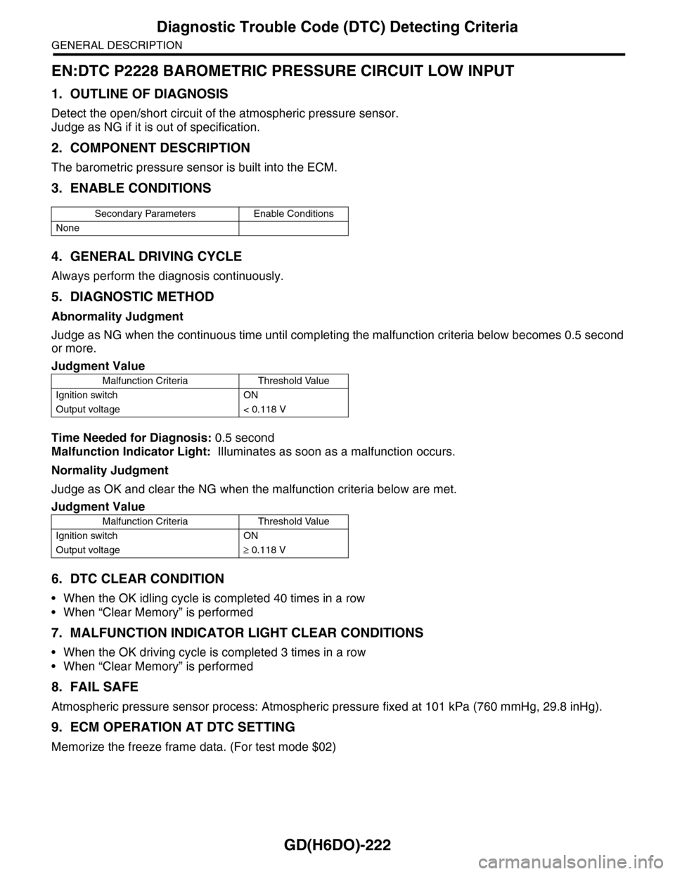
EN:DTC P2228 BAROMETRIC PRESSURE CIRCUIT LOW INPUT
1. OUTLINE OF DIAGNOSIS
Detect the open/short circuit of the atmospheric pressure sensor.
Judge as NG if it is out of specification.
2. COMPONENT DESCRIPTION
The barometric pressure sensor is built into the ECM.
3. ENABLE CONDITIONS
4. GENERAL DRIVING CYCLE
Always perform the diagnosis continuously.
5. DIAGNOSTIC METHOD
Abnormality Judgment
Judge as NG when the continuous time until completing the malfunction criteria below becomes 0.5 second
or more.
Time Needed for Diagnosis: 0.5 second
Malfunction Indicator Light: Illuminates as soon as a malfunction occurs.
Normality Judgment
Judge as OK and clear the NG when the malfunction criteria below are met.
6. DTC CLEAR CONDITION
•When the OK idling cycle is completed 40 times in a row
•When “Clear Memory” is performed
7. MALFUNCTION INDICATOR LIGHT CLEAR CONDITIONS
•When the OK driving cycle is completed 3 times in a row
•When “Clear Memory” is performed
8. FAIL SAFE
Atmospheric pressure sensor process: Atmospheric pressure fixed at 101 kPa (760 mmHg, 29.8 inHg).
9. ECM OPERATION AT DTC SETTING
Memorize the freeze frame data. (For test mode $02)
Secondary Parameters Enable Conditions
None
Judgment Value
Malfunction Criteria Threshold Value
Ignition switch ON
Output voltage < 0.118 V
Judgment Value
Malfunction Criteria Threshold Value
Ignition switch ON
Output voltage≥ 0.118 V
Page 1835 of 2453
GD(H6DO)-223
Diagnostic Trouble Code (DTC) Detecting Criteria
GENERAL DESCRIPTION
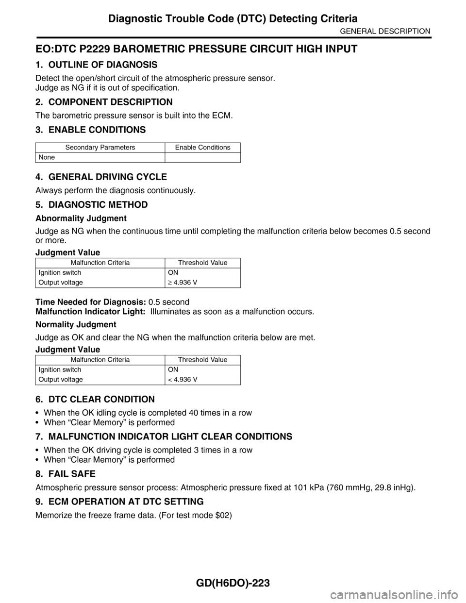
EO:DTC P2229 BAROMETRIC PRESSURE CIRCUIT HIGH INPUT
1. OUTLINE OF DIAGNOSIS
Detect the open/short circuit of the atmospheric pressure sensor.
Judge as NG if it is out of specification.
2. COMPONENT DESCRIPTION
The barometric pressure sensor is built into the ECM.
3. ENABLE CONDITIONS
4. GENERAL DRIVING CYCLE
Always perform the diagnosis continuously.
5. DIAGNOSTIC METHOD
Abnormality Judgment
Judge as NG when the continuous time until completing the malfunction criteria below becomes 0.5 second
or more.
Time Needed for Diagnosis: 0.5 second
Malfunction Indicator Light: Illuminates as soon as a malfunction occurs.
Normality Judgment
Judge as OK and clear the NG when the malfunction criteria below are met.
6. DTC CLEAR CONDITION
•When the OK idling cycle is completed 40 times in a row
•When “Clear Memory” is performed
7. MALFUNCTION INDICATOR LIGHT CLEAR CONDITIONS
•When the OK driving cycle is completed 3 times in a row
•When “Clear Memory” is performed
8. FAIL SAFE
Atmospheric pressure sensor process: Atmospheric pressure fixed at 101 kPa (760 mmHg, 29.8 inHg).
9. ECM OPERATION AT DTC SETTING
Memorize the freeze frame data. (For test mode $02)
Secondary Parameters Enable Conditions
None
Judgment Value
Malfunction Criteria Threshold Value
Ignition switch ON
Output voltage≥ 4.936 V
Judgment Value
Malfunction Criteria Threshold Value
Ignition switch ON
Output voltage < 4.936 V
Page 1956 of 2453
ME(H6DO)-90
Engine Noise
MECHANICAL
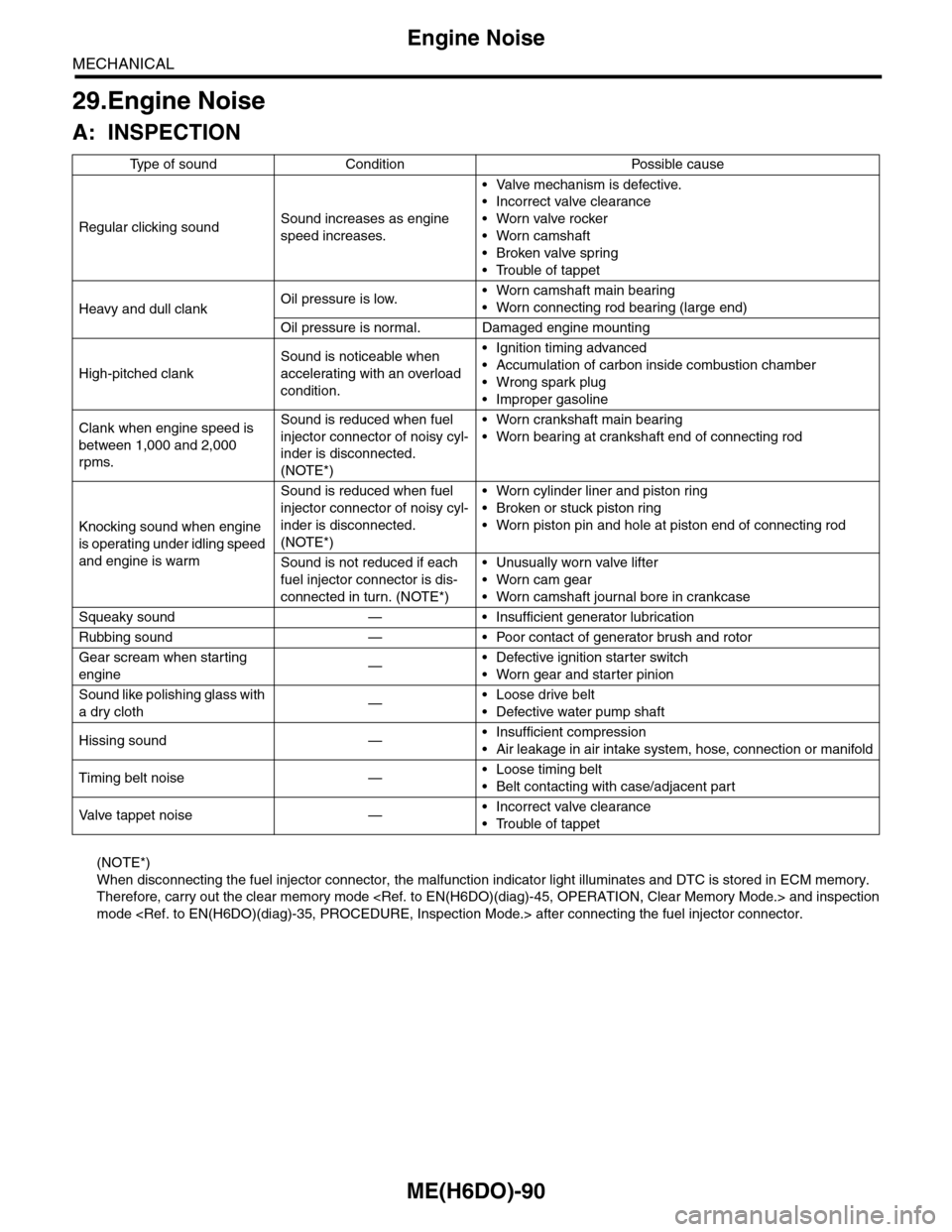
29.Engine Noise
A: INSPECTION
(NOTE*)
When disconnecting the fuel injector connector, the malfunction indicator light illuminates and DTC is stored in ECM memory.
Therefore, carry out the clear memory mode and inspection
mode after connecting the fuel injector connector.
Ty p e o f s o u n d C o n d i t i o n P o s s i b l e c a u s e
Regular clicking soundSound increases as engine
speed increases.
•Valve mechanism is defective.
•Incorrect valve clearance
•Worn valve rocker
•Worn camshaft
•Broken valve spring
•Trouble of tappet
Heavy and dull clankOil pressure is low.•Worn camshaft main bearing
•Worn connecting rod bearing (large end)
Oil pressure is normal. Damaged engine mounting
High-pitched clank
Sound is noticeable when
accelerating with an overload
condition.
•Ignition timing advanced
•Accumulation of carbon inside combustion chamber
•Wrong spark plug
•Improper gasoline
Clank when engine speed is
between 1,000 and 2,000
rpms.
Sound is reduced when fuel
injector connector of noisy cyl-
inder is disconnected.
(NOTE*)
•Worn crankshaft main bearing
•Worn bearing at crankshaft end of connecting rod
Knocking sound when engine
is operating under idling speed
and engine is warm
Sound is reduced when fuel
injector connector of noisy cyl-
inder is disconnected.
(NOTE*)
•Worn cylinder liner and piston ring
•Broken or stuck piston ring
•Worn piston pin and hole at piston end of connecting rod
Sound is not reduced if each
fuel injector connector is dis-
connected in turn. (NOTE*)
•Unusually worn valve lifter
•Worn cam gear
•Worn camshaft journal bore in crankcase
Squeaky sound — • Insufficient generator lubrication
Rubbing sound — • Poor contact of generator brush and rotor
Gear scream when starting
engine—•Defective ignition starter switch
•Worn gear and starter pinion
Sound like polishing glass with
a dry cloth—•Loose drive belt
•Defective water pump shaft
Hissing sound —•Insufficient compression
•Air leakage in air intake system, hose, connection or manifold
Timing belt noise —•Loose timing belt
•Belt contacting with case/adjacent part
Va l ve t a p p e t n o i s e —•Incorrect valve clearance
•Trouble of tappet
Page 2122 of 2453
5AT(diag)-5
General Description
AUTOMATIC TRANSMISSION (DIAGNOSTICS)
3. General Description
A: CAUTION
•SRS AIRBAG SYSTEM
The airbag system wiring harness is routed near
the TCM.
CAUTION:
•All air bag system wiring harnesses and con-
nectors are colored yellow. Do not use an elec-
tric test equipment to check these circuits.
•Be careful not to damage the airbag system
wiring harness when performing diagnostics or
servicing the TCM.
•MEASUREMENT
When measuring the voltage and resistance of the
ECM, TCM or each sensor, use a tapered pin with
a diameter of less than 0.64 mm (0.025 in) in order
to avoid poor contact. Do not insert a pin of more
than 0.65 mm (0.026 in) diameter.
B: INSPECTION
1. BATTERY
Measure the battery voltage and specific gravity of
electrolyte.
Standard voltage: 12 V or more
Specific gravity: 1.260 or more
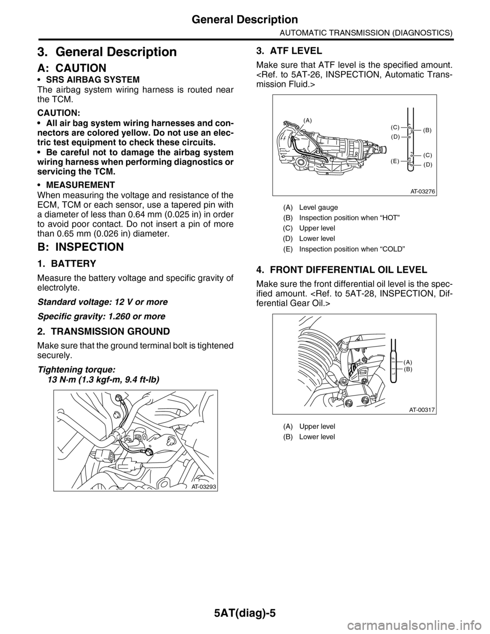
2. TRANSMISSION GROUND
Make sure that the ground terminal bolt is tightened
securely.
Tightening torque:
13 N·m (1.3 kgf-m, 9.4 ft-lb)
3. ATF LEVEL
Make sure that ATF level is the specified amount.
mission Fluid.>
4. FRONT DIFFERENTIAL OIL LEVEL
Make sure the front differential oil level is the spec-
ified amount.
ferential Gear Oil.>
AT-03293
(A) Level gauge
(B) Inspection position when “HOT”
(C) Upper level
(D) Lower level
(E) Inspection position when “COLD”
(A) Upper level
(B) Lower level
AT-03276
COLDLF
HOTLF
(C)
(D)
(C)
(D)
(E)
(B)
(A)
AT-00317
(A)(B)L
F
Page 2124 of 2453
5AT(diag)-7
Electrical Component Location
AUTOMATIC TRANSMISSION (DIAGNOSTICS)
4. Electrical Component Location
A: LOCATION
1. CONTROL MODULE
(1) Engine control module (ECM) (3) Transmission control module
(TCM)
(4) Data link connector
(2) SPORT indicator light (AT warning
light)
(5) Body integrated unit
AT-03278
(1)
(3)(4) (2) (5)
EN-03680
(1)
AT-03279(2)
(3)
(5)
AT-03296EN-03683
(4)