2009 SUBARU TRIBECA Harness
[x] Cancel search: HarnessPage 1542 of 2453
EN(H6DO)(diag)-381
Diagnostic Procedure with Diagnostic Trouble Code (DTC)
ENGINE (DIAGNOSTICS)
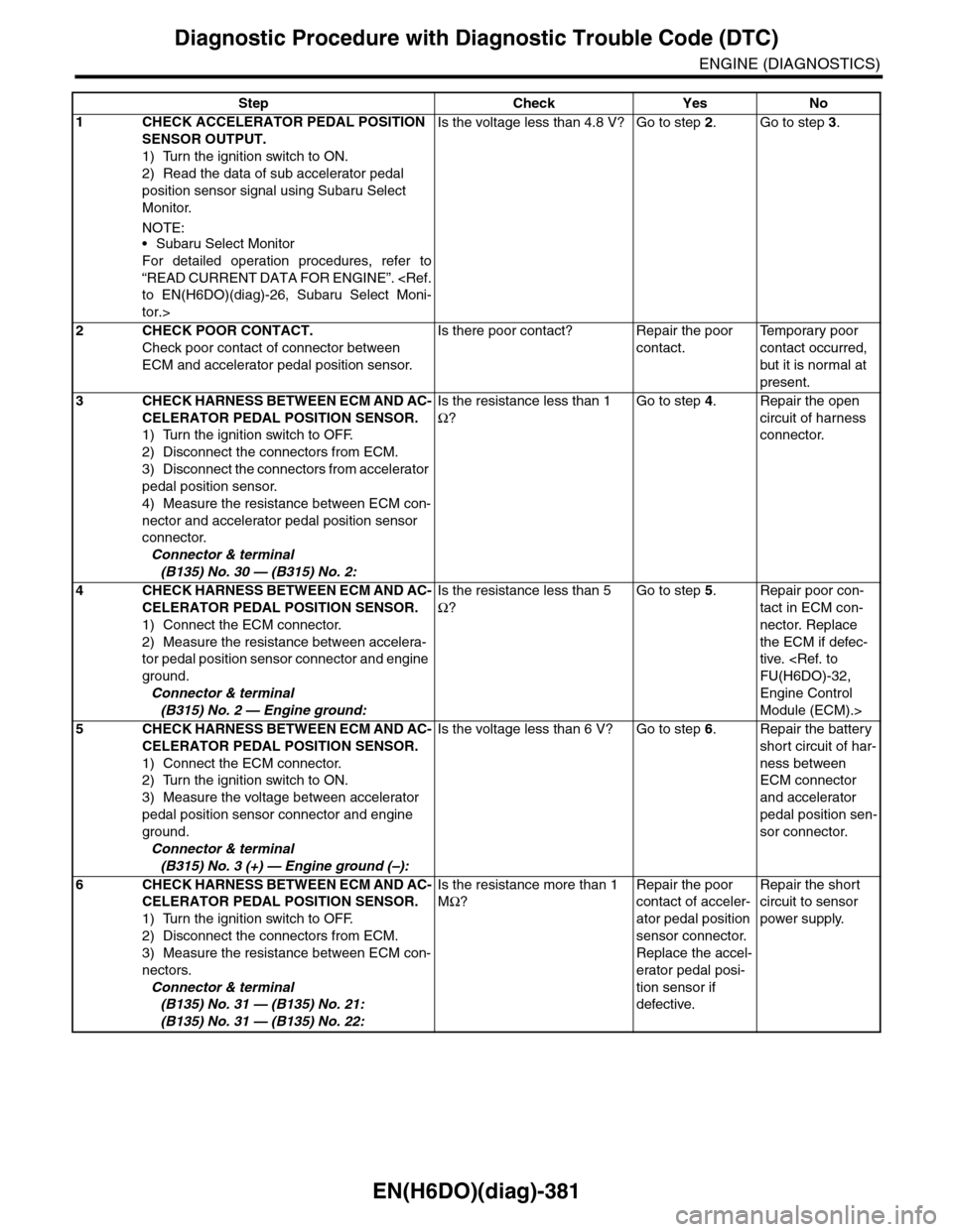
Step Check Yes No
1CHECK ACCELERATOR PEDAL POSITION
SENSOR OUTPUT.
1) Turn the ignition switch to ON.
2) Read the data of sub accelerator pedal
position sensor signal using Subaru Select
Monitor.
NOTE:•Subaru Select Monitor
For detailed operation procedures, refer to
“READ CURRENT DATA FOR ENGINE”.
tor.>
Is the voltage less than 4.8 V? Go to step 2.Go to step 3.
2CHECK POOR CONTACT.
Check poor contact of connector between
ECM and accelerator pedal position sensor.
Is there poor contact? Repair the poor
contact.
Te m p o r a r y p o o r
contact occurred,
but it is normal at
present.
3CHECK HARNESS BETWEEN ECM AND AC-
CELERATOR PEDAL POSITION SENSOR.
1) Turn the ignition switch to OFF.
2) Disconnect the connectors from ECM.
3) Disconnect the connectors from accelerator
pedal position sensor.
4) Measure the resistance between ECM con-
nector and accelerator pedal position sensor
connector.
Connector & terminal
(B135) No. 30 — (B315) No. 2:
Is the resistance less than 1
Ω?
Go to step 4.Repair the open
circuit of harness
connector.
4CHECK HARNESS BETWEEN ECM AND AC-
CELERATOR PEDAL POSITION SENSOR.
1) Connect the ECM connector.
2) Measure the resistance between accelera-
tor pedal position sensor connector and engine
ground.
Connector & terminal
(B315) No. 2 — Engine ground:
Is the resistance less than 5
Ω?
Go to step 5.Repair poor con-
tact in ECM con-
nector. Replace
the ECM if defec-
tive.
Engine Control
Module (ECM).>
5CHECK HARNESS BETWEEN ECM AND AC-
CELERATOR PEDAL POSITION SENSOR.
1) Connect the ECM connector.
2) Turn the ignition switch to ON.
3) Measure the voltage between accelerator
pedal position sensor connector and engine
ground.
Connector & terminal
(B315) No. 3 (+) — Engine ground (–):
Is the voltage less than 6 V? Go to step 6.Repair the battery
short circuit of har-
ness between
ECM connector
and accelerator
pedal position sen-
sor connector.
6CHECK HARNESS BETWEEN ECM AND AC-
CELERATOR PEDAL POSITION SENSOR.
1) Turn the ignition switch to OFF.
2) Disconnect the connectors from ECM.
3) Measure the resistance between ECM con-
nectors.
Connector & terminal
(B135) No. 31 — (B135) No. 21:
(B135) No. 31 — (B135) No. 22:
Is the resistance more than 1
MΩ?
Repair the poor
contact of acceler-
ator pedal position
sensor connector.
Replace the accel-
erator pedal posi-
tion sensor if
defective.
Repair the short
circuit to sensor
power supply.
Page 1544 of 2453
EN(H6DO)(diag)-383
Diagnostic Procedure with Diagnostic Trouble Code (DTC)
ENGINE (DIAGNOSTICS)
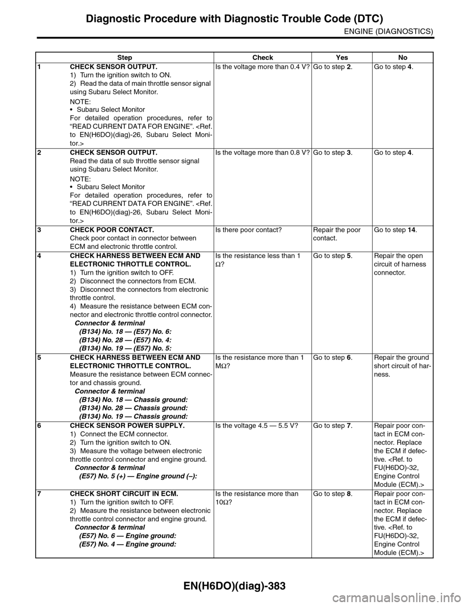
Step Check Yes No
1CHECK SENSOR OUTPUT.
1) Turn the ignition switch to ON.
2) Read the data of main throttle sensor signal
using Subaru Select Monitor.
NOTE:•Subaru Select Monitor
For detailed operation procedures, refer to
“READ CURRENT DATA FOR ENGINE”.
tor.>
Is the voltage more than 0.4 V? Go to step 2.Go to step 4.
2CHECK SENSOR OUTPUT.
Read the data of sub throttle sensor signal
using Subaru Select Monitor.
NOTE:•Subaru Select Monitor
For detailed operation procedures, refer to
“READ CURRENT DATA FOR ENGINE”.
tor.>
Is the voltage more than 0.8 V? Go to step 3.Go to step 4.
3CHECK POOR CONTACT.
Check poor contact in connector between
ECM and electronic throttle control.
Is there poor contact? Repair the poor
contact.
Go to step 14.
4CHECK HARNESS BETWEEN ECM AND
ELECTRONIC THROTTLE CONTROL.
1) Turn the ignition switch to OFF.
2) Disconnect the connectors from ECM.
3) Disconnect the connectors from electronic
throttle control.
4) Measure the resistance between ECM con-
nector and electronic throttle control connector.
Connector & terminal
(B134) No. 18 — (E57) No. 6:
(B134) No. 28 — (E57) No. 4:
(B134) No. 19 — (E57) No. 5:
Is the resistance less than 1
Ω?
Go to step 5.Repair the open
circuit of harness
connector.
5CHECK HARNESS BETWEEN ECM AND
ELECTRONIC THROTTLE CONTROL.
Measure the resistance between ECM connec-
tor and chassis ground.
Connector & terminal
(B134) No. 18 — Chassis ground:
(B134) No. 28 — Chassis ground:
(B134) No. 19 — Chassis ground:
Is the resistance more than 1
MΩ?
Go to step 6.Repair the ground
short circuit of har-
ness.
6CHECK SENSOR POWER SUPPLY.
1) Connect the ECM connector.
2) Turn the ignition switch to ON.
3) Measure the voltage between electronic
throttle control connector and engine ground.
Connector & terminal
(E57) No. 5 (+) — Engine ground (–):
Is the voltage 4.5 — 5.5 V? Go to step 7.Repair poor con-
tact in ECM con-
nector. Replace
the ECM if defec-
tive.
Engine Control
Module (ECM).>
7CHECK SHORT CIRCUIT IN ECM.
1) Turn the ignition switch to OFF.
2) Measure the resistance between electronic
throttle control connector and engine ground.
Connector & terminal
(E57) No. 6 — Engine ground:
(E57) No. 4 — Engine ground:
Is the resistance more than
10Ω?
Go to step 8.Repair poor con-
tact in ECM con-
nector. Replace
the ECM if defec-
tive.
Engine Control
Module (ECM).>
Page 1545 of 2453
EN(H6DO)(diag)-384
Diagnostic Procedure with Diagnostic Trouble Code (DTC)
ENGINE (DIAGNOSTICS)
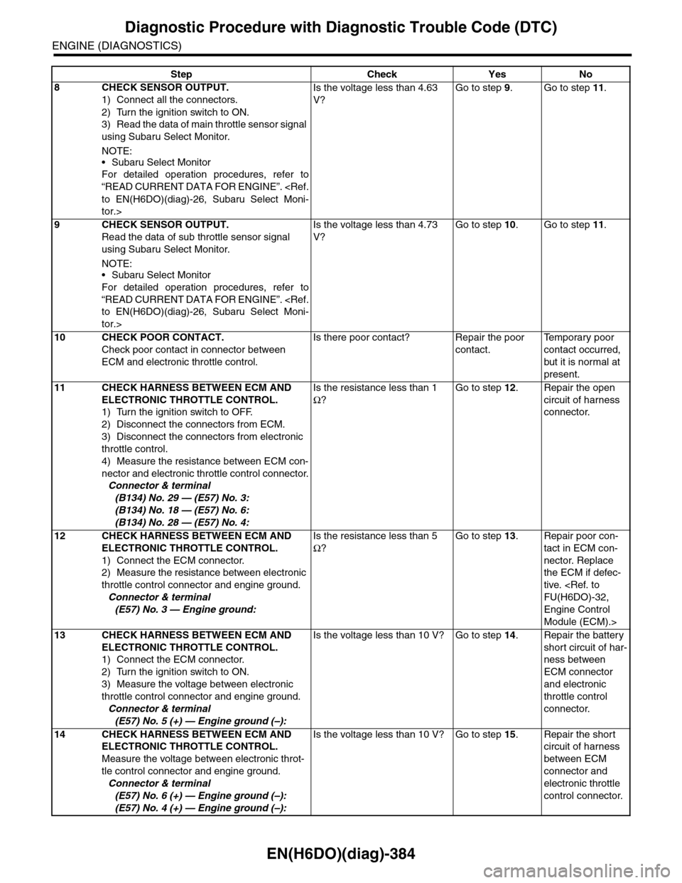
8CHECK SENSOR OUTPUT.
1) Connect all the connectors.
2) Turn the ignition switch to ON.
3) Read the data of main throttle sensor signal
using Subaru Select Monitor.
NOTE:
•Subaru Select Monitor
For detailed operation procedures, refer to
“READ CURRENT DATA FOR ENGINE”.
tor.>
Is the voltage less than 4.63
V?
Go to step 9.Go to step 11.
9CHECK SENSOR OUTPUT.
Read the data of sub throttle sensor signal
using Subaru Select Monitor.
NOTE:•Subaru Select Monitor
For detailed operation procedures, refer to
“READ CURRENT DATA FOR ENGINE”.
tor.>
Is the voltage less than 4.73
V?
Go to step 10.Go to step 11.
10 CHECK POOR CONTACT.
Check poor contact in connector between
ECM and electronic throttle control.
Is there poor contact? Repair the poor
contact.
Te m p o r a r y p o o r
contact occurred,
but it is normal at
present.
11 CHECK HARNESS BETWEEN ECM AND
ELECTRONIC THROTTLE CONTROL.
1) Turn the ignition switch to OFF.
2) Disconnect the connectors from ECM.
3) Disconnect the connectors from electronic
throttle control.
4) Measure the resistance between ECM con-
nector and electronic throttle control connector.
Connector & terminal
(B134) No. 29 — (E57) No. 3:
(B134) No. 18 — (E57) No. 6:
(B134) No. 28 — (E57) No. 4:
Is the resistance less than 1
Ω?
Go to step 12.Repair the open
circuit of harness
connector.
12 CHECK HARNESS BETWEEN ECM AND
ELECTRONIC THROTTLE CONTROL.
1) Connect the ECM connector.
2) Measure the resistance between electronic
throttle control connector and engine ground.
Connector & terminal
(E57) No. 3 — Engine ground:
Is the resistance less than 5
Ω?
Go to step 13.Repair poor con-
tact in ECM con-
nector. Replace
the ECM if defec-
tive.
Engine Control
Module (ECM).>
13 CHECK HARNESS BETWEEN ECM AND
ELECTRONIC THROTTLE CONTROL.
1) Connect the ECM connector.
2) Turn the ignition switch to ON.
3) Measure the voltage between electronic
throttle control connector and engine ground.
Connector & terminal
(E57) No. 5 (+) — Engine ground (–):
Is the voltage less than 10 V? Go to step 14.Repair the battery
short circuit of har-
ness between
ECM connector
and electronic
throttle control
connector.
14 CHECK HARNESS BETWEEN ECM AND
ELECTRONIC THROTTLE CONTROL.
Measure the voltage between electronic throt-
tle control connector and engine ground.
Connector & terminal
(E57) No. 6 (+) — Engine ground (–):
(E57) No. 4 (+) — Engine ground (–):
Is the voltage less than 10 V? Go to step 15.Repair the short
circuit of harness
between ECM
connector and
electronic throttle
control connector.
Step Check Yes No
Page 1546 of 2453
EN(H6DO)(diag)-385
Diagnostic Procedure with Diagnostic Trouble Code (DTC)
ENGINE (DIAGNOSTICS)
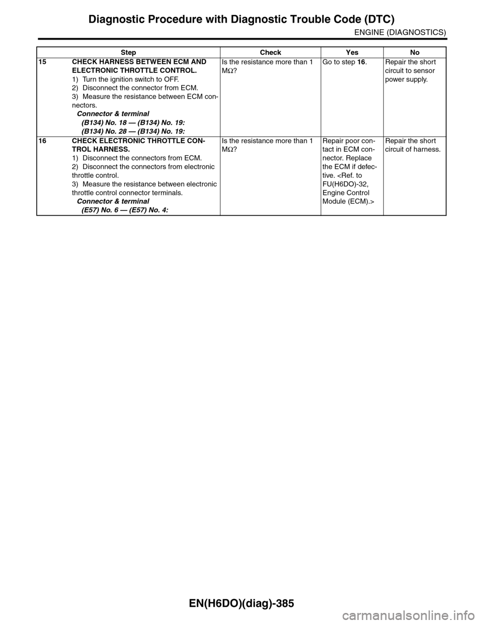
15 CHECK HARNESS BETWEEN ECM AND
ELECTRONIC THROTTLE CONTROL.
1) Turn the ignition switch to OFF.
2) Disconnect the connector from ECM.
3) Measure the resistance between ECM con-
nectors.
Connector & terminal
(B134) No. 18 — (B134) No. 19:
(B134) No. 28 — (B134) No. 19:
Is the resistance more than 1
MΩ?
Go to step 16.Repair the short
circuit to sensor
power supply.
16 CHECK ELECTRONIC THROTTLE CON-
TROL HARNESS.
1) Disconnect the connectors from ECM.
2) Disconnect the connectors from electronic
throttle control.
3) Measure the resistance between electronic
throttle control connector terminals.
Connector & terminal
(E57) No. 6 — (E57) No. 4:
Is the resistance more than 1
MΩ?
Repair poor con-
tact in ECM con-
nector. Replace
the ECM if defec-
tive.
Engine Control
Module (ECM).>
Repair the short
circuit of harness.
Step Check Yes No
Page 1548 of 2453
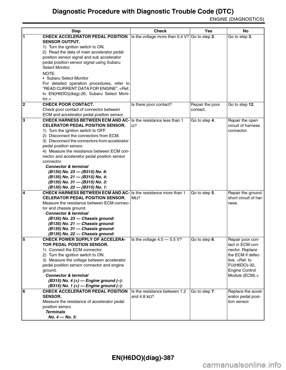
EN(H6DO)(diag)-387
Diagnostic Procedure with Diagnostic Trouble Code (DTC)
ENGINE (DIAGNOSTICS)
Step Check Yes No
1CHECK ACCELERATOR PEDAL POSITION
SENSOR OUTPUT.
1) Turn the ignition switch to ON.
2) Read the data of main accelerator pedal
position sensor signal and sub accelerator
pedal position sensor signal using Subaru
Select Monitor.
NOTE:•Subaru Select Monitor
For detailed operation procedures, refer to
“READ CURRENT DATA FOR ENGINE”.
tor.>
Is the voltage more than 0.4 V? Go to step 2.Go to step 3.
2CHECK POOR CONTACT.
Check poor contact of connector between
ECM and accelerator pedal position sensor.
Is there poor contact? Repair the poor
contact.
Go to step 12.
3CHECK HARNESS BETWEEN ECM AND AC-
CELERATOR PEDAL POSITION SENSOR.
1) Turn the ignition switch to OFF.
2) Disconnect the connectors from ECM.
3) Disconnect the connectors from accelerator
pedal position sensor.
4) Measure the resistance between ECM con-
nector and accelerator pedal position sensor
connector.
Connector & terminal
(B135) No. 23 — (B315) No. 6:
(B135) No. 21 — (B315) No. 4:
(B135) No. 31 — (B315) No. 3:
(B135) No. 22 — (B315) No. 1:
Is the resistance less than 1
Ω?
Go to step 4.Repair the open
circuit of harness
connector.
4CHECK HARNESS BETWEEN ECM AND AC-
CELERATOR PEDAL POSITION SENSOR.
Measure the resistance between ECM connec-
tor and chassis ground.
Connector & terminal
(B135) No. 23 — Chassis ground:
(B135) No. 21 — Chassis ground:
(B135) No. 31 — Chassis ground:
(B135) No. 22 — Chassis ground:
Is the resistance more than 1
MΩ?
Go to step 5.Repair the ground
short circuit of har-
ness.
5CHECK POWER SUPPLY OF ACCELERA-
TOR PEDAL POSITION SENSOR.
1) Connect the ECM connector.
2) Turn the ignition switch to ON.
3) Measure the voltage between accelerator
pedal position sensor connector and engine
ground.
Connector & terminal
(B315) No. 4 (+) — Engine ground (–):
(B315) No. 1 (+) — Engine ground (–):
Is the voltage 4.5 — 5.5 V? Go to step 6.Repair poor con-
tact in ECM con-
nector. Replace
the ECM if defec-
tive.
Engine Control
Module (ECM).>
6CHECK ACCELERATOR PEDAL POSITION
SENSOR.
Measure the resistance of accelerator pedal
position sensor.
Te r m i n a l s
No. 4 — No. 5:
Is the resistance between 1.2
and 4.8 kΩ?
Go to step 7.Replace the accel-
erator pedal posi-
tion sensor.
Page 1550 of 2453
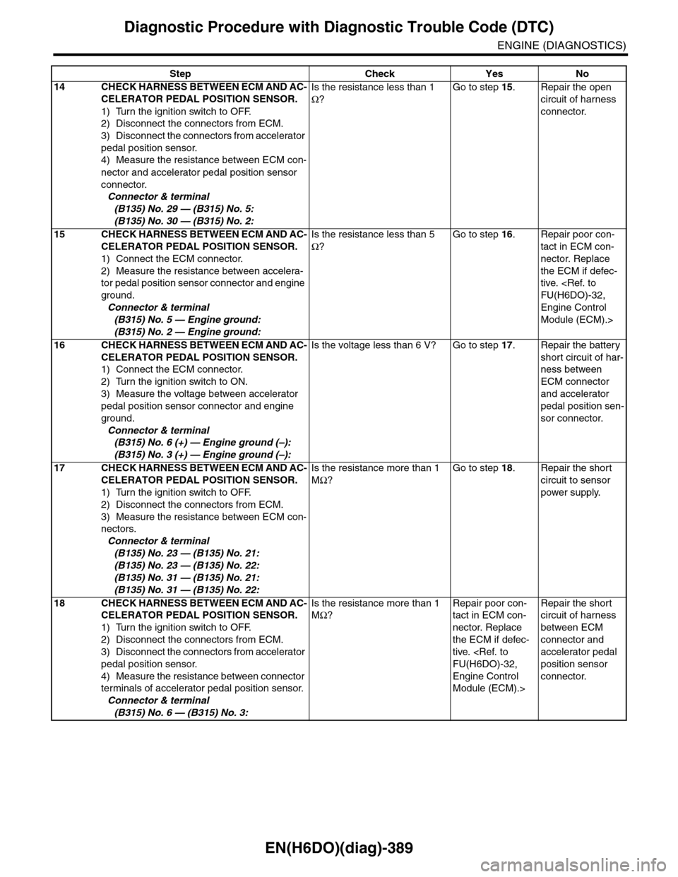
EN(H6DO)(diag)-389
Diagnostic Procedure with Diagnostic Trouble Code (DTC)
ENGINE (DIAGNOSTICS)
14 CHECK HARNESS BETWEEN ECM AND AC-
CELERATOR PEDAL POSITION SENSOR.
1) Turn the ignition switch to OFF.
2) Disconnect the connectors from ECM.
3) Disconnect the connectors from accelerator
pedal position sensor.
4) Measure the resistance between ECM con-
nector and accelerator pedal position sensor
connector.
Connector & terminal
(B135) No. 29 — (B315) No. 5:
(B135) No. 30 — (B315) No. 2:
Is the resistance less than 1
Ω?
Go to step 15.Repair the open
circuit of harness
connector.
15 CHECK HARNESS BETWEEN ECM AND AC-
CELERATOR PEDAL POSITION SENSOR.
1) Connect the ECM connector.
2) Measure the resistance between accelera-
tor pedal position sensor connector and engine
ground.
Connector & terminal
(B315) No. 5 — Engine ground:
(B315) No. 2 — Engine ground:
Is the resistance less than 5
Ω?
Go to step 16.Repair poor con-
tact in ECM con-
nector. Replace
the ECM if defec-
tive.
Engine Control
Module (ECM).>
16 CHECK HARNESS BETWEEN ECM AND AC-
CELERATOR PEDAL POSITION SENSOR.
1) Connect the ECM connector.
2) Turn the ignition switch to ON.
3) Measure the voltage between accelerator
pedal position sensor connector and engine
ground.
Connector & terminal
(B315) No. 6 (+) — Engine ground (–):
(B315) No. 3 (+) — Engine ground (–):
Is the voltage less than 6 V? Go to step 17.Repair the battery
short circuit of har-
ness between
ECM connector
and accelerator
pedal position sen-
sor connector.
17 CHECK HARNESS BETWEEN ECM AND AC-
CELERATOR PEDAL POSITION SENSOR.
1) Turn the ignition switch to OFF.
2) Disconnect the connectors from ECM.
3) Measure the resistance between ECM con-
nectors.
Connector & terminal
(B135) No. 23 — (B135) No. 21:
(B135) No. 23 — (B135) No. 22:
(B135) No. 31 — (B135) No. 21:
(B135) No. 31 — (B135) No. 22:
Is the resistance more than 1
MΩ?
Go to step 18.Repair the short
circuit to sensor
power supply.
18 CHECK HARNESS BETWEEN ECM AND AC-
CELERATOR PEDAL POSITION SENSOR.
1) Turn the ignition switch to OFF.
2) Disconnect the connectors from ECM.
3) Disconnect the connectors from accelerator
pedal position sensor.
4) Measure the resistance between connector
terminals of accelerator pedal position sensor.
Connector & terminal
(B315) No. 6 — (B315) No. 3:
Is the resistance more than 1
MΩ?
Repair poor con-
tact in ECM con-
nector. Replace
the ECM if defec-
tive.
Engine Control
Module (ECM).>
Repair the short
circuit of harness
between ECM
connector and
accelerator pedal
position sensor
connector.
Step Check Yes No
Page 1573 of 2453
FU(H6DO)-12
Intake Manifold
FUEL INJECTION (FUEL SYSTEMS)
3. Intake Manifold
A: REMOVAL
1) Remove the collector cover.
2) Release the fuel pressure.
DURE, Fuel.>
3) Disconnect the ground cable from battery.
4) Open the fuel filler flap lid, and remove the fuel
filler cap.
5) Remove the air cleaner case and air intake
chamber.
6) Remove the generator.
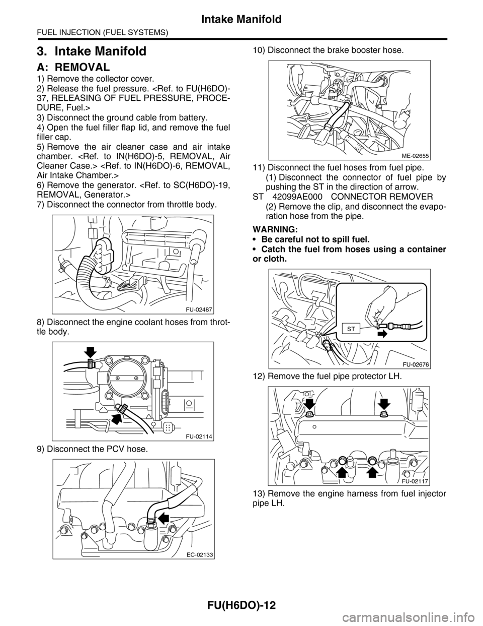
7) Disconnect the connector from throttle body.
8) Disconnect the engine coolant hoses from throt-
tle body.
9) Disconnect the PCV hose.
10) Disconnect the brake booster hose.
11) Disconnect the fuel hoses from fuel pipe.
(1) Disconnect the connector of fuel pipe by
pushing the ST in the direction of arrow.
ST 42099AE000 CONNECTOR REMOVER
(2) Remove the clip, and disconnect the evapo-
ration hose from the pipe.
WARNING:
•Be careful not to spill fuel.
•Catch the fuel from hoses using a container
or cloth.
12) Remove the fuel pipe protector LH.
13) Remove the engine harness from fuel injector
pipe LH.
FU-02487
FU-02114
EC-02133
ME-02655
FU-02117
Page 1574 of 2453
FU(H6DO)-13
Intake Manifold
FUEL INJECTION (FUEL SYSTEMS)
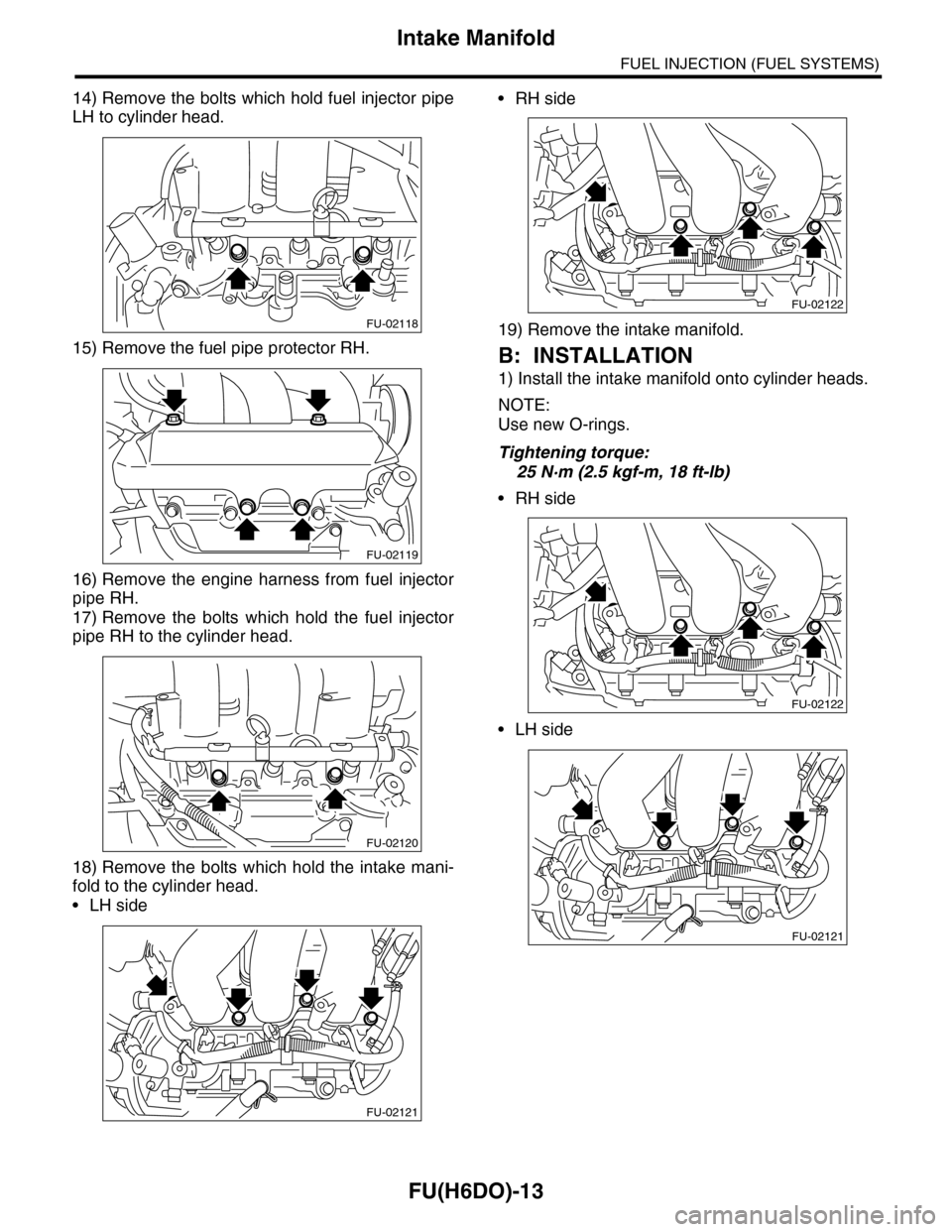
14) Remove the bolts which hold fuel injector pipe
LH to cylinder head.
15) Remove the fuel pipe protector RH.
16) Remove the engine harness from fuel injector
pipe RH.
17) Remove the bolts which hold the fuel injector
pipe RH to the cylinder head.
18) Remove the bolts which hold the intake mani-
fold to the cylinder head.
•LH side
•RH side
19) Remove the intake manifold.
B: INSTALLATION
1) Install the intake manifold onto cylinder heads.
NOTE:
Use new O-rings.
Tightening torque:
25 N·m (2.5 kgf-m, 18 ft-lb)
•RH side
•LH side
FU-02118
FU-02119
FU-02120
FU-02121
FU-02122
FU-02122
FU-02121