Page 1953 of 2453

ME(H6DO)-87
Engine Trouble in General
MECHANICAL
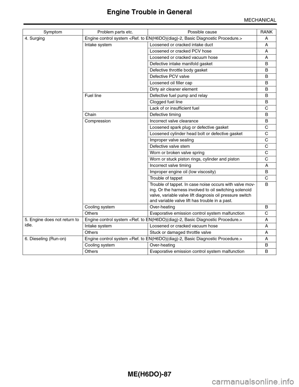
4. Surging Engine control system A
Intake system Loosened or cracked intake duct A
Loosened or cracked PCV hose A
Loosened or cracked vacuum hose A
Defective intake manifold gasket B
Defective throttle body gasket B
Defective PCV valve B
Loosened oil filler cap B
Dirty air cleaner element B
Fuel line Defective fuel pump and relay B
Clogged fuel line B
Lack of or insufficient fuel C
Chain Defective timing B
Compression Incorrect valve clearance B
Loosened spark plug or defective gasket C
Loosened cylinder head bolt or defective gasket C
Improper valve sealing C
Defective valve stem C
Wor n or broken valve spr ing C
Wor n or stuck piston r ings, cylinder and piston C
Incorrect valve timing A
Improper engine oil (low viscosity) B
Tr o u b l e o f t a p p e t C
Tr o u b l e o f t a p p e t . I n c a s e n o i s e o c c u r s w i t h v a l v e m o v -
ing. Or the harness involved to oil switching solenoid
valve, variable valve lift diagnosis oil pressure switch
and variable valve lift has trouble in a past.
B
Cooling system Over-heating B
Others Evaporative emission control system malfunction C
5. Engine does not return to
idle.
Engine control system A
Intake system Loosened or cracked vacuum hose A
Others Stuck or damaged throttle valve A
6. Dieseling (Run-on) Engine control system A
Cooling system Over-heating B
Others Evaporative emission control system malfunction B
Symptom Problem parts etc. Possible cause RANK
Page 1954 of 2453

ME(H6DO)-88
Engine Trouble in General
MECHANICAL
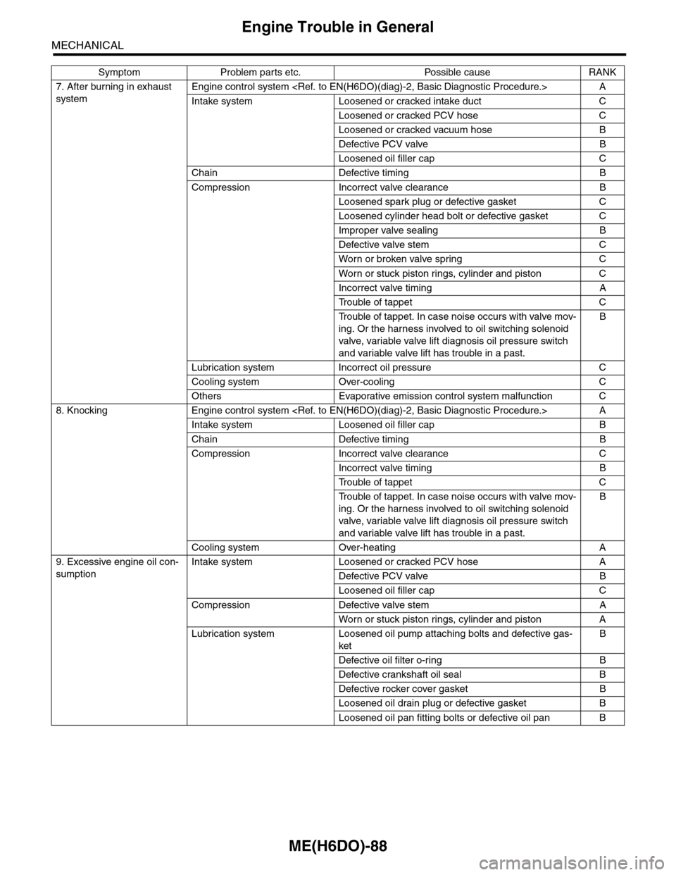
7. After burning in exhaust
system
Engine control system A
Intake system Loosened or cracked intake duct C
Loosened or cracked PCV hose C
Loosened or cracked vacuum hose B
Defective PCV valve B
Loosened oil filler cap C
Chain Defective timing B
Compression Incorrect valve clearance B
Loosened spark plug or defective gasket C
Loosened cylinder head bolt or defective gasket C
Improper valve sealing B
Defective valve stem C
Wor n or broken valve spr ing C
Wor n or stuck piston r ings, cylinder and piston C
Incorrect valve timing A
Tr o u b l e o f t a p p e t C
Tr o u b l e o f t a p p e t . I n c a s e n o i s e o c c u r s w i t h v a l v e m o v -
ing. Or the harness involved to oil switching solenoid
valve, variable valve lift diagnosis oil pressure switch
and variable valve lift has trouble in a past.
B
Lubrication system Incorrect oil pressure C
Cooling system Over-cooling C
Others Evaporative emission control system malfunction C
8. Knocking Engine control system A
Intake system Loosened oil filler cap B
Chain Defective timing B
Compression Incorrect valve clearance C
Incorrect valve timing B
Tr o u b l e o f t a p p e t C
Tr o u b l e o f t a p p e t . I n c a s e n o i s e o c c u r s w i t h v a l v e m o v -
ing. Or the harness involved to oil switching solenoid
valve, variable valve lift diagnosis oil pressure switch
and variable valve lift has trouble in a past.
B
Cooling system Over-heating A
9. Excessive engine oil con-
sumption
Intake system Loosened or cracked PCV hose A
Defective PCV valve B
Loosened oil filler cap C
Compression Defective valve stem A
Wor n or stuck piston r ings, cylinder and piston A
Lubrication system Loosened oil pump attaching bolts and defective gas-
ket
B
Defective oil filter o-ring B
Defective crankshaft oil seal B
Defective rocker cover gasket B
Loosened oil drain plug or defective gasket B
Loosened oil pan fitting bolts or defective oil pan B
Symptom Problem parts etc. Possible cause RANK
Page 1955 of 2453
ME(H6DO)-89
Engine Trouble in General
MECHANICAL
10. Excessive fuel consump-
tion
Engine control system A
Intake system Dirty air cleaner element A
Chain Defective timing B
Compression Incorrect valve clearance B
Loosened spark plug or defective gasket C
Loosened cylinder head bolt or defective gasket C
Improper valve sealing B
Defective valve stem C
Wor n or broken valve spr ing C
Wor n or stuck piston r ings, cylinder and piston B
Incorrect valve timing B
Tr o u b l e o f t a p p e t C
Tr o u b l e o f t a p p e t . I n c a s e n o i s e o c c u r s w i t h v a l v e m o v -
ing. Or the harness involved to oil switching solenoid
valve, variable valve lift diagnosis oil pressure switch
and variable valve lift has trouble in a past.
B
Lubrication system Incorrect oil pressure C
Cooling system Over-cooling C
Symptom Problem parts etc. Possible cause RANK
Page 1972 of 2453
SC(H6DO)-14
Starter
STARTING/CHARGING SYSTEMS
20) Install the rear cover.
21) Install the magnet switch assembly to front
bracket.
(1) Assemble the plunger hook to lever.
NOTE:
Apply grease to the plunger hook and sleeve inner
circumference.
Grease:
DENSO HL50
(2) Assemble the plunger spring and magnet
switch to front bracket.
NOTE:
Apply grease to the end surface of magnet switch
as shown in the figure.
Grease:
DENSO HL50
(3) Tighten the bolt.
Tightening torque:
7.5 N·m (0.8 kgf-m, 5.5 ft-lb)
22) Connect the harness to terminal M of magnet
switch assembly.
Tightening torque:
10 N·m (1.0 kgf-m, 7.4 ft-lb)
(A) Lever
(B) Plunger hook
(A) 5 mm
SC-02041
SC-02074
(A)
(B)
SC-02075
(A)
(A) Plunger
(B) Plunger spring
(C) Magnet switch
(A) Terminal M
SC-02076
(C)
(B)(A)
SC-02040
(A)
SC-02039
Page 1975 of 2453

SC(H6DO)-17
Starter
STARTING/CHARGING SYSTEMS
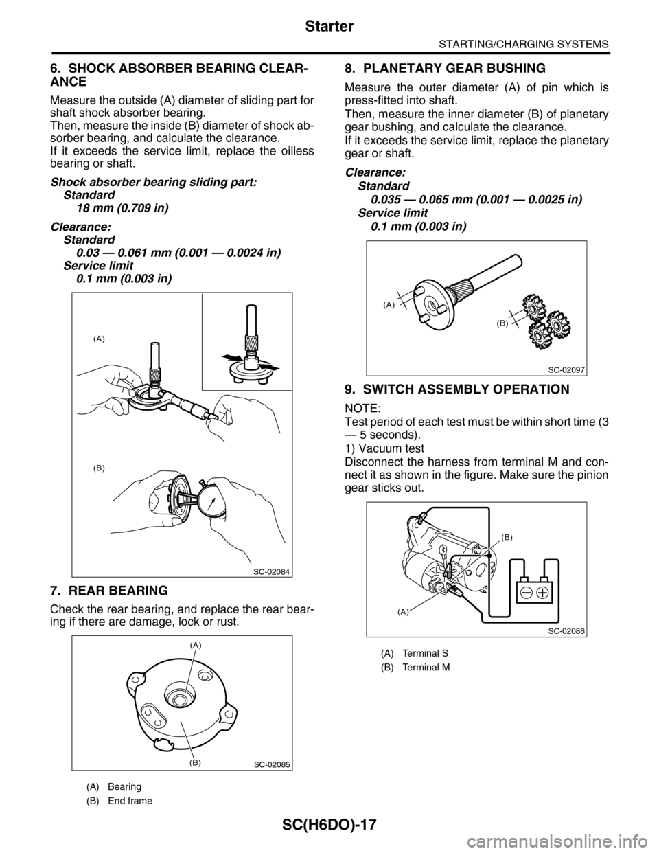
6. SHOCK ABSORBER BEARING CLEAR-
ANCE
Measure the outside (A) diameter of sliding part for
shaft shock absorber bearing.
Then, measure the inside (B) diameter of shock ab-
sorber bearing, and calculate the clearance.
If it exceeds the service limit, replace the oilless
bearing or shaft.
Shock absorber bearing sliding part:
Standard
18 mm (0.709 in)
Clearance:
Standard
0.03 — 0.061 mm (0.001 — 0.0024 in)
Service limit
0.1 mm (0.003 in)
7. REAR BEARING
Check the rear bearing, and replace the rear bear-
ing if there are damage, lock or rust.
8. PLANETARY GEAR BUSHING
Measure the outer diameter (A) of pin which is
press-fitted into shaft.
Then, measure the inner diameter (B) of planetary
gear bushing, and calculate the clearance.
If it exceeds the service limit, replace the planetary
gear or shaft.
Clearance:
Standard
0.035 — 0.065 mm (0.001 — 0.0025 in)
Service limit
0.1 mm (0.003 in)
9. SWITCH ASSEMBLY OPERATION
NOTE:
Test period of each test must be within short time (3
— 5 seconds).
1) Vacuum test
Disconnect the harness from terminal M and con-
nect it as shown in the figure. Make sure the pinion
gear sticks out.
(A) Bearing
(B) End frame
SC-02084
(A)
(B)
SC-02085
(A)
(B)
(A) Terminal S
(B) Terminal M
SC-02097
(A)
(B)
SC-02086
(A)
(B)
Page 2019 of 2453
5AT-3
General Description
AUTOMATIC TRANSMISSION
8. COOLING AND HARNESS
9. TRANSFER
10.FINAL REDUCTION GEAR
11.RECOMMENDED GEAR OIL
Cooling systemLiquid-cooler incorporated in
radiator
Tr a n s m i s s i o n h a r n e s s 2 0 + 8 p o l e s
Tr a n s f e r t y p eVa r i a b l e t o r q u e d i s t r i b u t i o n
(VTD)
Number of transfer clutch
drives & driven plates4
Reduction gear ratio 1.000 (41/41)
Fr o nt f in a l r e du ct i o n g ea r
ratio3.583
Lubrication oil
(1) Item (3) API standard
(2) Front differential gear oil (4) SAE viscosity No. and applicable
temperature
Fr o nt d if fer e nt i a l g ea r oi l c a pa ci t y
2(US qt, Imp qt)1.3 — 1.5 (1.4 — 1.6, 1.1 — 1.3)
MT-00001
(1)
(4)GL-5(3)
(2)
( C)( F)-30 -26 -15 15
9085W80W75W -90
25 30 -5 0-22-1523328659775
Page 2025 of 2453
5AT-9
General Description
AUTOMATIC TRANSMISSION
6. CONTROL VALVE & TRANSMISSION HARNESS
(1) Transmission harness ASSY (4) ClipTightening torque: N·m (kgf-m, ft-lb)
(3) Harness bracket (5) Control valve ASSYT1: 7(0.7, 5.2)
(2) Front vehicle speed sensor
(1)
(2)
(3)
(4)
(5)
T1
T1
T1
AT-03254
Page 2050 of 2453

5AT-34
Automatic Transmission Assembly
AUTOMATIC TRANSMISSION
9. Automatic Transmission As-
sembly
A: REMOVAL
1) Set the vehicle on a lift.
2) Open the front hood and support with the hood
stay.
3) Disconnect the ground cable from battery.
4) Remove the collector cover.
5) Remove the air intake chamber.
IN(H6DO)-6, REMOVAL, Air Intake Chamber.>
6) Remove the air breather hose.
REMOVAL, Air Breather Hose.>
7) Remove the starter.
MOVAL, Starter.>
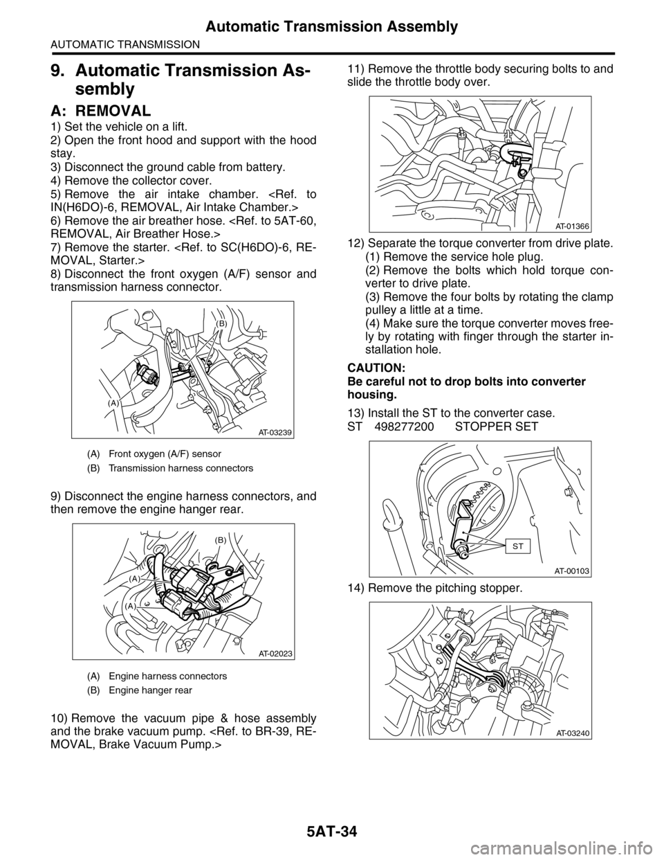
8) Disconnect the front oxygen (A/F) sensor and
transmission harness connector.
9) Disconnect the engine harness connectors, and
then remove the engine hanger rear.
10) Remove the vacuum pipe & hose assembly
and the brake vacuum pump.
MOVAL, Brake Vacuum Pump.>
11) Remove the throttle body securing bolts to and
slide the throttle body over.
12) Separate the torque converter from drive plate.
(1) Remove the service hole plug.
(2) Remove the bolts which hold torque con-
verter to drive plate.
(3) Remove the four bolts by rotating the clamp
pulley a little at a time.
(4) Make sure the torque converter moves free-
ly by rotating with finger through the starter in-
stallation hole.
CAUTION:
Be careful not to drop bolts into converter
housing.
13) Install the ST to the converter case.
ST 498277200 STOPPER SET
14) Remove the pitching stopper.
(A) Front oxygen (A/F) sensor
(B) Transmission harness connectors
(A) Engine harness connectors
(B) Engine hanger rear
(A)
(B)
AT-03239
(B)
(A)
(A)
AT-02023
AT-01366
AT-00103
ST
AT-03240