Page 1575 of 2453
FU(H6DO)-14
Intake Manifold
FUEL INJECTION (FUEL SYSTEMS)
2) Install the bolts which hold fuel injector pipe RH
to cylinder head.
Tightening torque:
19 N·m (1.9 kgf-m, 14 ft-lb)
3) Install the engine harness to fuel injector pipe
RH.
4) Install the fuel pipe protector RH.
Tightening torque:
19 N·m (1.9 kgf-m, 14 ft-lb)
5) Install the bolts which hold fuel injector pipe LH
to cylinder head.
Tightening torque:
19 N·m (1.9 kgf-m, 14 ft-lb)
6) Install the engine harness to fuel injector pipe
LH.
7) Install the fuel pipe protector LH.
Tightening torque:
19 N·m (1.9 kgf-m, 14 ft-lb)
8) Connect the fuel hoses to fuel pipe.
9) Connect the brake booster hose.
10) Connect the PCV hose.
FU-02120
FU-02119
FU-02118
FU-02117
ME-02384
ME-02655
EC-02133
Page 1576 of 2453
FU(H6DO)-15
Intake Manifold
FUEL INJECTION (FUEL SYSTEMS)
11) Connect the engine coolant hoses to throttle
body.
12) Connect the connector to throttle body.
13) Install the generator.
INSTALLATION, Generator.>
14) Install the air cleaner case and air intake cham-
ber.
Cleaner Case.>
TION, Air Intake Chamber.>
15) Install the fuse of fuel pump to main fuse box.
16) Connect the ground cable to the battery.
17) Install the collector cover.
C: DISASSEMBLY
1) Remove the engine harness from intake mani-
fold.
2) Remove the throttle body.
11, REMOVAL, Throttle Body.>
3) Remove the manifold absolute pressure sensor.
solute Pressure Sensor.>
4) Remove the purge control solenoid valve.
to EC(H6DO)-6, REMOVAL, Purge Control Sole-
noid Valve.>
5) Loosen the clamp which holds fuel injector pipe
to fuel hose, and then disconnect the pipe from fuel
hose.
6) Remove the bolts which install fuel pipes on in-
take manifold.
FU-02114
FU-02487FU-02124
FU-02125
FU-02126
Page 1577 of 2453
FU(H6DO)-16
Intake Manifold
FUEL INJECTION (FUEL SYSTEMS)
D: ASSEMBLY
NOTE:
When assembling the nipple, apply liquid gasket.
Liquid gasket:
THREE BOND 1105 (Part No.004403010)
1) Tighten the bolts which install fuel pipes on in-
take manifold.
Tightening torque:
6.4 N·m (0.65 kgf-m, 4.7 ft-lb)
2) Connect the fuel injector pipe to fuel hose, and
tighten the clamp screw.
Tightening torque:
1.5 N·m (0.15 kgf-m, 1.1 ft-lb)
3) Install the purge control solenoid valve.
EC(H6DO)-6, INSTALLATION, Purge Control So-
lenoid Valve.>
4) Install the manifold absolute pressure sensor.
Absolute Pressure Sensor.>
5) Install the throttle body to intake manifold.
to FU(H6DO)-11, INSTALLATION, Throttle Body.>
6) Install the engine harness to the intake manifold.
E: INSPECTION
Make sure the fuel pipe and fuel hoses are not
damaged and the connections are tightened firmly.
FU-02125
FU-02126
FU-02124
Page 1580 of 2453
FU(H6DO)-19
Camshaft Position Sensor
FUEL INJECTION (FUEL SYSTEMS)
6. Camshaft Position Sensor
A: REMOVAL
1) Remove the collector cover.
2) Disconnect the ground cable from battery.
3) Remove the generator harness from fuel pipe
protector LH.
4) Remove the fuel pipe protector LH.
5) Disconnect the connector from camshaft posi-
tion sensor LH.
6) Remove the camshaft position sensor LH.
7) Remove the camshaft position sensor RH in the
same procedure as LH.
B: INSTALLATION
Install in the reverse order of removal.
Tightening torque:
Camshaft position sensor
6.4 N·m (0.65 kgf-m, 4.7 ft-lb)
Fuel pipe protector
19 N·m (1.9 kgf-m, 14 ft-lb)
FU-02117
FU-02129
FU-02130
Page 1585 of 2453

FU(H6DO)-24
Fuel Injector
FUEL INJECTION (FUEL SYSTEMS)
11.Fuel Injector
A: REMOVAL
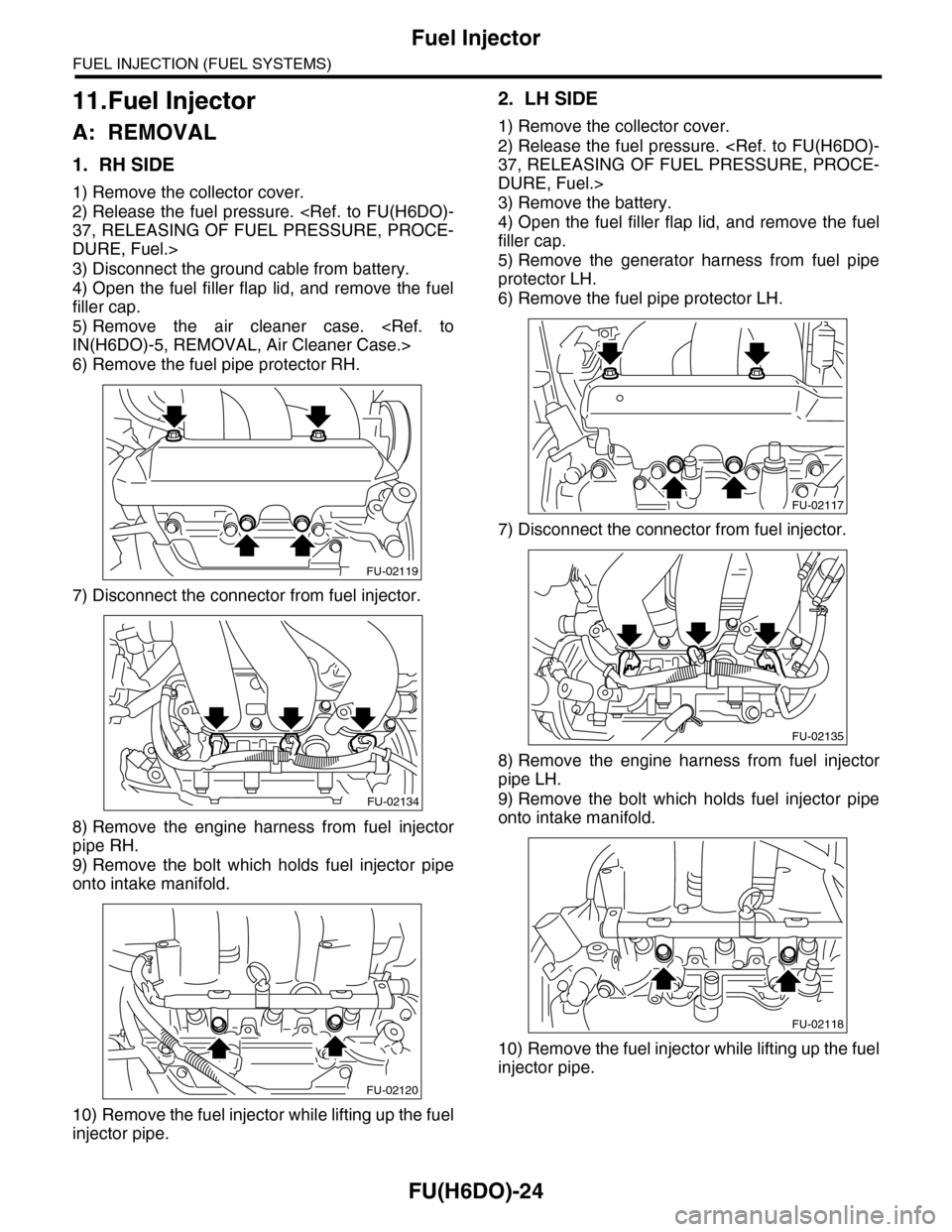
1. RH SIDE
1) Remove the collector cover.
2) Release the fuel pressure.
37, RELEASING OF FUEL PRESSURE, PROCE-
DURE, Fuel.>
3) Disconnect the ground cable from battery.
4) Open the fuel filler flap lid, and remove the fuel
filler cap.
5) Remove the air cleaner case.
IN(H6DO)-5, REMOVAL, Air Cleaner Case.>
6) Remove the fuel pipe protector RH.
7) Disconnect the connector from fuel injector.
8) Remove the engine harness from fuel injector
pipe RH.
9) Remove the bolt which holds fuel injector pipe
onto intake manifold.
10) Remove the fuel injector while lifting up the fuel
injector pipe.
2. LH SIDE
1) Remove the collector cover.
2) Release the fuel pressure.
37, RELEASING OF FUEL PRESSURE, PROCE-
DURE, Fuel.>
3) Remove the battery.
4) Open the fuel filler flap lid, and remove the fuel
filler cap.
5) Remove the generator harness from fuel pipe
protector LH.
6) Remove the fuel pipe protector LH.
7) Disconnect the connector from fuel injector.
8) Remove the engine harness from fuel injector
pipe LH.
9) Remove the bolt which holds fuel injector pipe
onto intake manifold.
10) Remove the fuel injector while lifting up the fuel
injector pipe.
FU-02119
FU-02134
FU-02120
FU-02117
FU-02135
FU-02118
Page 1591 of 2453

FU(H6DO)-30
Rear Oxygen Sensor
FUEL INJECTION (FUEL SYSTEMS)
15.Rear Oxygen Sensor
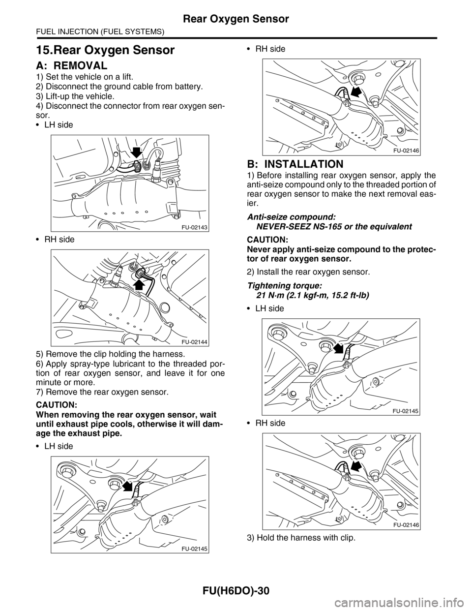
A: REMOVAL
1) Set the vehicle on a lift.
2) Disconnect the ground cable from battery.
3) Lift-up the vehicle.
4) Disconnect the connector from rear oxygen sen-
sor.
•LH side
•RH side
5) Remove the clip holding the harness.
6) Apply spray-type lubricant to the threaded por-
tion of rear oxygen sensor, and leave it for one
minute or more.
7) Remove the rear oxygen sensor.
CAUTION:
When removing the rear oxygen sensor, wait
until exhaust pipe cools, otherwise it will dam-
age the exhaust pipe.
•LH side
•RH side
B: INSTALLATION
1) Before installing rear oxygen sensor, apply the
anti-seize compound only to the threaded portion of
rear oxygen sensor to make the next removal eas-
ier.
Anti-seize compound:
NEVER-SEEZ NS-165 or the equivalent
CAUTION:
Never apply anti-seize compound to the protec-
tor of rear oxygen sensor.
2) Install the rear oxygen sensor.
Tightening torque:
21 N·m (2.1 kgf-m, 15.2 ft-lb)
•LH side
•RH side
3) Hold the harness with clip.
FU-02143
FU-02144
FU-02145
FU-02146
FU-02145
FU-02146
Page 1593 of 2453
FU(H6DO)-32
Engine Control Module (ECM)
FUEL INJECTION (FUEL SYSTEMS)
16.Engine Control Module (ECM)
A: REMOVAL
1) Disconnect the ground cable from battery.
2) Remove the front pillar lower trim and console
side panel lower RH of passenger's side.
3) Detach the floor mat of passenger's seat.
4) Remove the protect cover.
5) Remove the nuts which hold the ECM to the
bracket.
6) Remove the clip (A) from bracket.
B: INSTALLATION
Install in the reverse order of removal.
CAUTION:
•When replacing the ECM, be careful not to
use the wrong spec. ECM to avoid any damage
on the fuel injection system.
•When replacing the ECM, be careful not to
damage the harnesses and connectors.
•When replacing the ECM, immobilizer system
must be registered. To do so, all ignition keys
and ID cards need to be prepared. Refer to the
“IMMOBILIZER TEACHING OPERATION MANU-
AL”.
Tightening torque:
5 N·m (0.5 kgf-m, 3.6 ft-lb)
FU-02090
FU-02682
Page 1594 of 2453
FU(H6DO)-33
Main Relay
FUEL INJECTION (FUEL SYSTEMS)
17.Main Relay
A: REMOVAL
1) Disconnect the ground cable from battery.
2) Remove the glove box.
AL, Glove Box.>
3) Remove the harness cover (A).
4) Disconnect the connectors from main relay.
B: INSTALLATION
Install in the reverse order of removal.
FU-02092
(A)
FU-02406