Page 1595 of 2453
FU(H6DO)-34
Fuel Pump Relay
FUEL INJECTION (FUEL SYSTEMS)
18.Fuel Pump Relay
A: REMOVAL
1) Disconnect the ground cable from battery.
2) Remove the glove box.
AL, Glove Box.>
3) Remove the harness cover (A).
4) Disconnect the connector from fuel pump relay.
B: INSTALLATION
Install in the reverse order of removal.
FU-02092
(A)
FU-02407
Page 1596 of 2453
FU(H6DO)-35
Electronic Throttle Control Relay
FUEL INJECTION (FUEL SYSTEMS)
19.Electronic Throttle Control
Relay
A: REMOVAL
1) Disconnect the ground cable from battery.
2) Remove the glove box.
AL, Glove Box.>
3) Remove the harness cover (A).
4) Disconnect the connector from electric throttle
control relay.
B: INSTALLATION
Install in the reverse order of removal.
FU-02092
(A)
FU-02408
Page 1599 of 2453
FU(H6DO)-38
Fuel Tank
FUEL INJECTION (FUEL SYSTEMS)
22.Fuel Tank
A: REMOVAL
WARNING:
•Place “NO FIRE” signs near the working area.
•Be careful not to spill fuel on the floor.
1) Set the vehicle on a lift.
2) Release the fuel pressure.
37, RELEASING OF FUEL PRESSURE, PROCE-
DURE, Fuel.>
3) Disconnect the ground cable from battery.
4) Drain fuel from fuel tank.
CEDURE, Fuel.>
5) Remove the second seat.
MOVAL, Second-row Seats.>
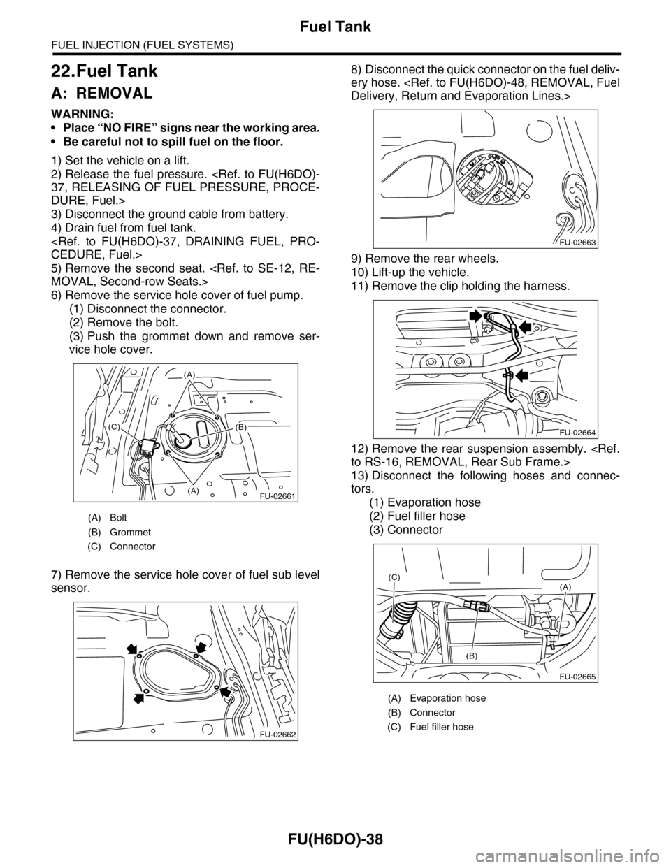
6) Remove the service hole cover of fuel pump.
(1) Disconnect the connector.
(2) Remove the bolt.
(3) Push the grommet down and remove ser-
vice hole cover.
7) Remove the service hole cover of fuel sub level
sensor.
8) Disconnect the quick connector on the fuel deliv-
ery hose.
Delivery, Return and Evaporation Lines.>
9) Remove the rear wheels.
10) Lift-up the vehicle.
11) Remove the clip holding the harness.
12) Remove the rear suspension assembly.
to RS-16, REMOVAL, Rear Sub Frame.>
13) Disconnect the following hoses and connec-
tors.
(1) Evaporation hose
(2) Fuel filler hose
(3) Connector
(A) Bolt
(B) Grommet
(C) Connector
FU-02661(A)
(A)
(B)(C)
FU-02662
(A) Evaporation hose
(B) Connector
(C) Fuel filler hose
FU-02663
FU-02664
FU-02665
(A)
(B)
(C)
Page 1600 of 2453
FU(H6DO)-39
Fuel Tank
FUEL INJECTION (FUEL SYSTEMS)
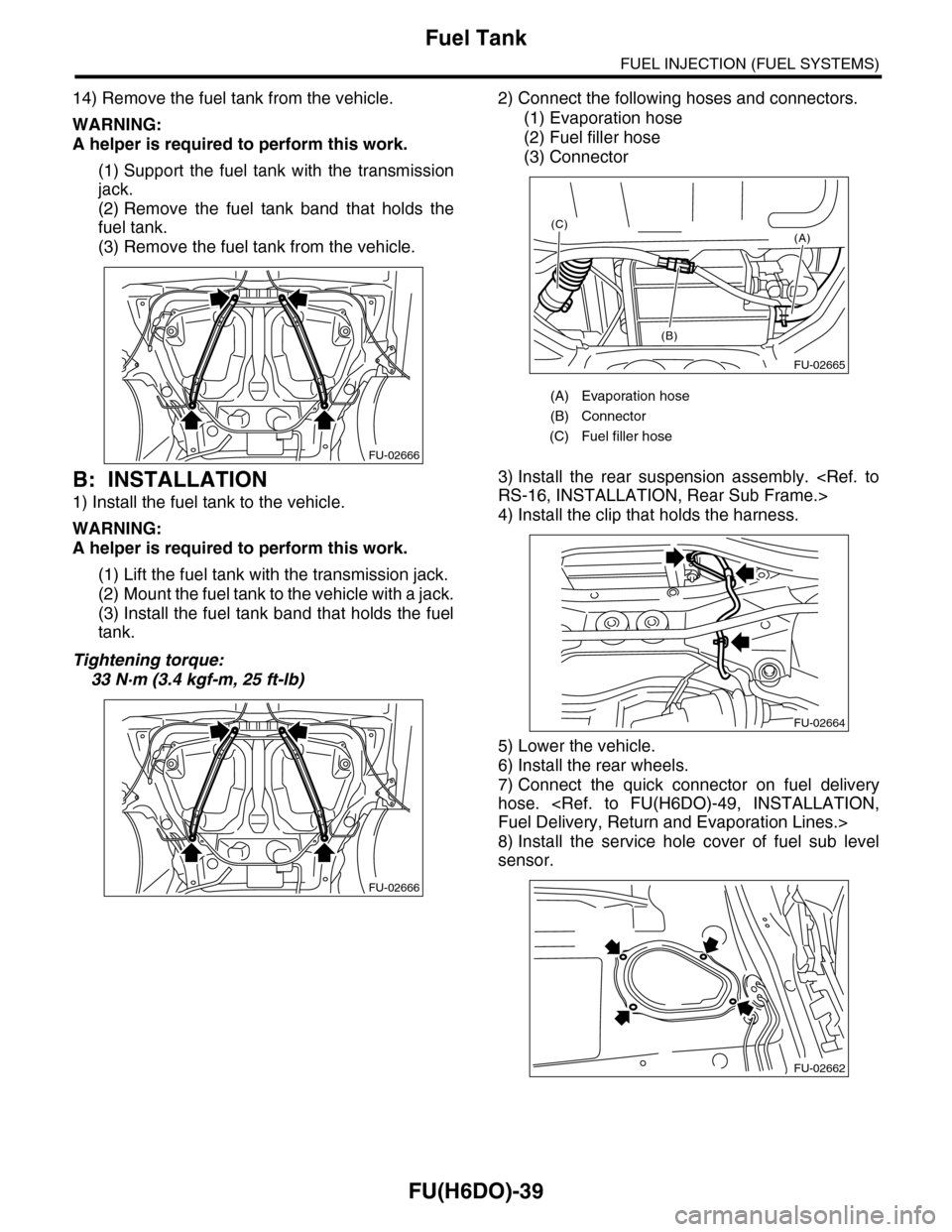
14) Remove the fuel tank from the vehicle.
WARNING:
A helper is required to perform this work.
(1) Support the fuel tank with the transmission
jack.
(2) Remove the fuel tank band that holds the
fuel tank.
(3) Remove the fuel tank from the vehicle.
B: INSTALLATION
1) Install the fuel tank to the vehicle.
WARNING:
A helper is required to perform this work.
(1) Lift the fuel tank with the transmission jack.
(2) Mount the fuel tank to the vehicle with a jack.
(3) Install the fuel tank band that holds the fuel
tank.
Tightening torque:
33 N·m (3.4 kgf-m, 25 ft-lb)
2) Connect the following hoses and connectors.
(1) Evaporation hose
(2) Fuel filler hose
(3) Connector
3) Install the rear suspension assembly.
RS-16, INSTALLATION, Rear Sub Frame.>
4) Install the clip that holds the harness.
5) Lower the vehicle.
6) Install the rear wheels.
7) Connect the quick connector on fuel delivery
hose.
Fuel Delivery, Return and Evaporation Lines.>
8) Install the service hole cover of fuel sub level
sensor.
FU-02666
FU-02666
(A) Evaporation hose
(B) Connector
(C) Fuel filler hose
FU-02665
(A)
(B)
(C)
FU-02664
FU-02662
Page 1605 of 2453
FU(H6DO)-44
Fuel Pump
FUEL INJECTION (FUEL SYSTEMS)
C: INSPECTION
Connect the lead harness to the connector terminal
of fuel pump, and apply the battery power supply to
check whether the pump operates.
WARNING:
•Wipe off fuel completely.
•Keep the battery as far apart from fuel pump
as possible.
•Be sure to turn the battery supply to ON and
OFF on the battery side.
•Do not run the fuel pump for a long time un-
der non-load condition.
FU-01330
246
135
Page 1722 of 2453
GD(H6DO)-110
Diagnostic Trouble Code (DTC) Detecting Criteria
GENERAL DESCRIPTION
BT:DTC P0327 KNOCK SENSOR 1 CIRCUIT LOW INPUT (BANK 1 OR SINGLE
SENSOR)
1. OUTLINE OF DIAGNOSIS
Detect the open or short circuit of knock sensor.
Judge as NG if it is out of specification.
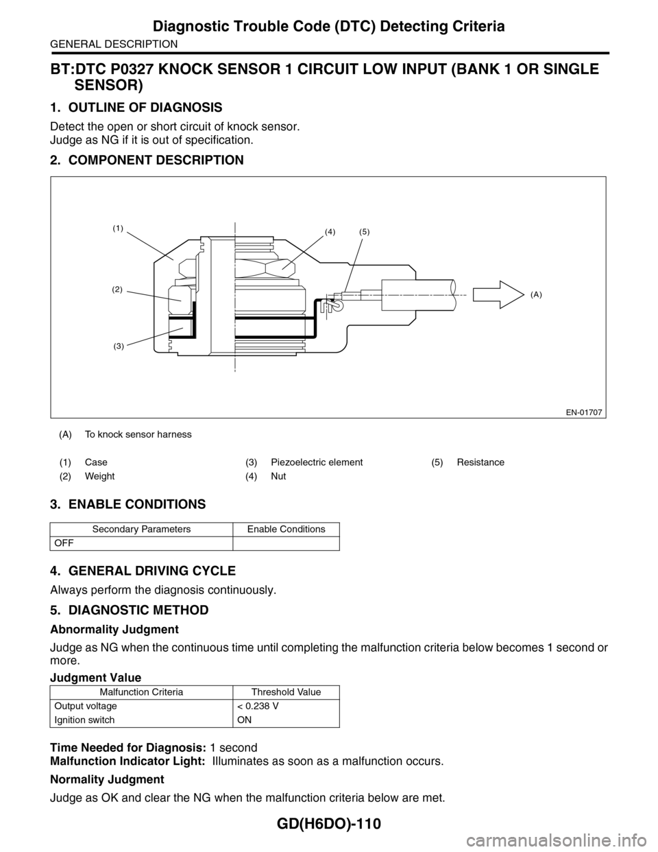
2. COMPONENT DESCRIPTION
3. ENABLE CONDITIONS
4. GENERAL DRIVING CYCLE
Always perform the diagnosis continuously.
5. DIAGNOSTIC METHOD
Abnormality Judgment
Judge as NG when the continuous time until completing the malfunction criteria below becomes 1 second or
more.
Time Needed for Diagnosis: 1 second
Malfunction Indicator Light: Illuminates as soon as a malfunction occurs.
Normality Judgment
Judge as OK and clear the NG when the malfunction criteria below are met.
(A) To knock sensor harness
(1) Case (3) Piezoelectric element (5) Resistance
(2) Weight (4) Nut
Secondary Parameters Enable Conditions
OFF
Judgment Value
Malfunction Criteria Threshold Value
Output voltage < 0.238 V
Ignition switch ON
EN-01707
(1)
(2)
(3)
(4)(5)
(A)
Page 1724 of 2453
GD(H6DO)-112
Diagnostic Trouble Code (DTC) Detecting Criteria
GENERAL DESCRIPTION
BU:DTC P0328 KNOCK SENSOR 1 CIRCUIT HIGH INPUT (BANK 1 OR SINGLE
SENSOR)
1. OUTLINE OF DIAGNOSIS
Detect the open or short circuit of knock sensor.
Judge as NG if it is out of specification.
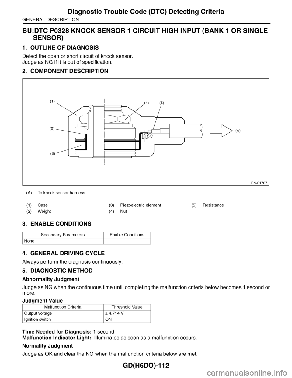
2. COMPONENT DESCRIPTION
3. ENABLE CONDITIONS
4. GENERAL DRIVING CYCLE
Always perform the diagnosis continuously.
5. DIAGNOSTIC METHOD
Abnormality Judgment
Judge as NG when the continuous time until completing the malfunction criteria below becomes 1 second or
more.
Time Needed for Diagnosis: 1 second
Malfunction Indicator Light: Illuminates as soon as a malfunction occurs.
Normality Judgment
Judge as OK and clear the NG when the malfunction criteria below are met.
(A) To knock sensor harness
(1) Case (3) Piezoelectric element (5) Resistance
(2) Weight (4) Nut
Secondary Parameters Enable Conditions
None
Judgment Value
Malfunction Criteria Threshold Value
Output voltage≥ 4.714 V
Ignition switch ON
EN-01707
(1)
(2)
(3)
(4)(5)
(A)
Page 1855 of 2453
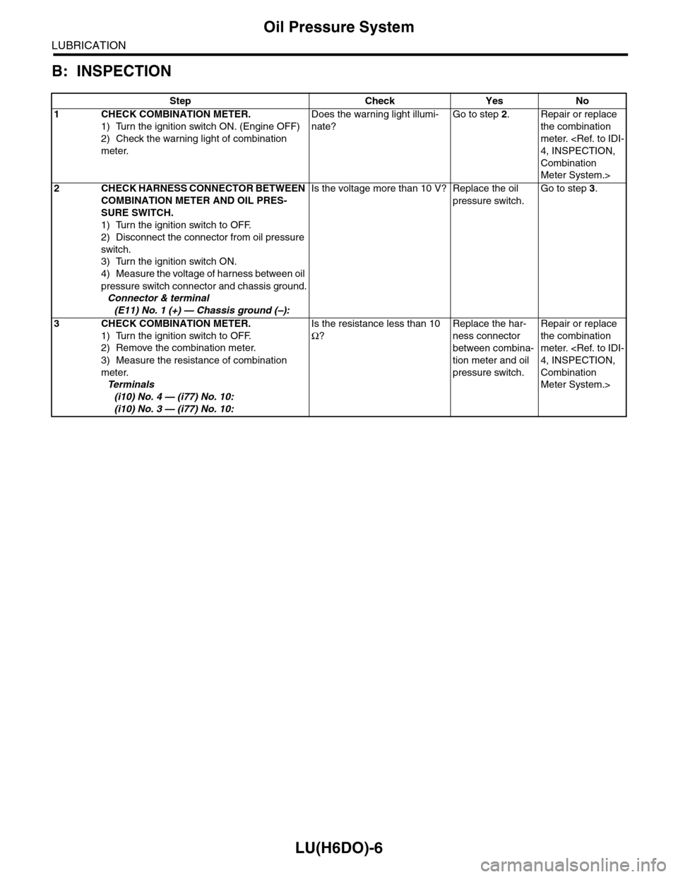
LU(H6DO)-6
Oil Pressure System
LUBRICATION
B: INSPECTION
Step Check Yes No
1CHECK COMBINATION METER.
1) Turn the ignition switch ON. (Engine OFF)
2) Check the warning light of combination
meter.
Does the warning light illumi-
nate?
Go to step 2.Repair or replace
the combination
meter.
4, INSPECTION,
Combination
Meter System.>
2CHECK HARNESS CONNECTOR BETWEEN
COMBINATION METER AND OIL PRES-
SURE SWITCH.
1) Turn the ignition switch to OFF.
2) Disconnect the connector from oil pressure
switch.
3) Turn the ignition switch ON.
4) Measure the voltage of harness between oil
pressure switch connector and chassis ground.
Connector & terminal
(E11) No. 1 (+) — Chassis ground (–):
Is the voltage more than 10 V? Replace the oil
pressure switch.
Go to step 3.
3CHECK COMBINATION METER.
1) Turn the ignition switch to OFF.
2) Remove the combination meter.
3) Measure the resistance of combination
meter.
Te r m i n a l s
(i10) No. 4 — (i77) No. 10:
(i10) No. 3 — (i77) No. 10:
Is the resistance less than 10
Ω?
Replace the har-
ness connector
between combina-
tion meter and oil
pressure switch.
Repair or replace
the combination
meter.
4, INSPECTION,
Combination
Meter System.>