2009 SUBARU TRIBECA Harness
[x] Cancel search: HarnessPage 2093 of 2453
5AT-77
Oil Pump Cover
AUTOMATIC TRANSMISSION
31.Oil Pump Cover
A: REMOVAL
1) Remove the transmission assembly from vehicle
body.
2) Pull out the torque converter assembly.
3) Remove the transmission harness connector
from stay.
4) Remove the oil charge pipe.
5) Remove the ATF filter inlet and outlet pipes.
6) Separate the converter case and transmission
case.
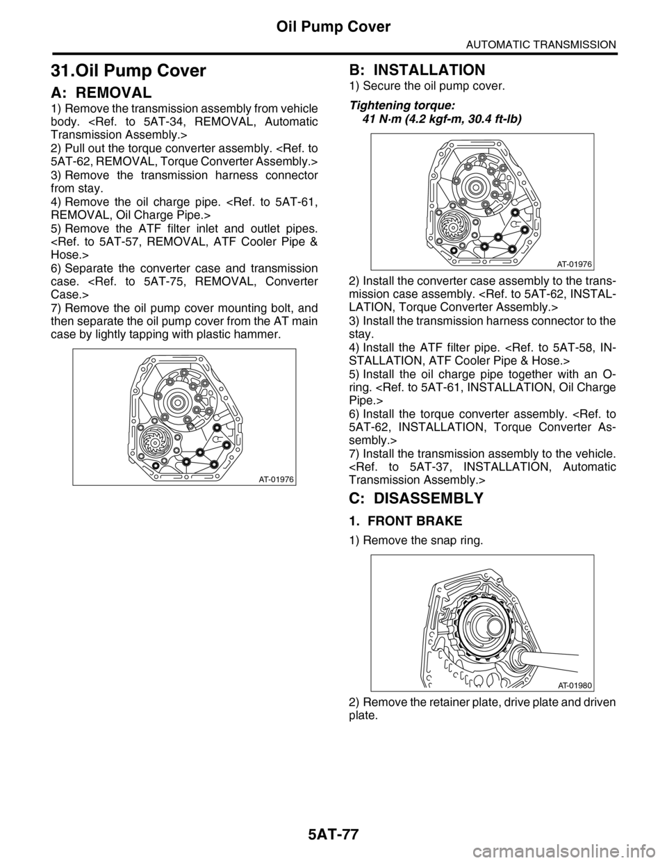
7) Remove the oil pump cover mounting bolt, and
then separate the oil pump cover from the AT main
case by lightly tapping with plastic hammer.
B: INSTALLATION
1) Secure the oil pump cover.
Tightening torque:
41 N·m (4.2 kgf-m, 30.4 ft-lb)
2) Install the converter case assembly to the trans-
mission case assembly.
3) Install the transmission harness connector to the
stay.
4) Install the ATF filter pipe.
5) Install the oil charge pipe together with an O-
ring.
6) Install the torque converter assembly.
sembly.>
7) Install the transmission assembly to the vehicle.
C: DISASSEMBLY
1. FRONT BRAKE
1) Remove the snap ring.
2) Remove the retainer plate, drive plate and driven
plate.
AT-01976
AT-01976
AT-01980
Page 2097 of 2453
5AT-81
Drive Pinion Shaft Assembly
AUTOMATIC TRANSMISSION
32.Drive Pinion Shaft Assembly
A: REMOVAL
1) Remove the transmission assembly from vehicle
body.
2) Pull out the torque converter assembly.
3) Remove the transmission harness connector
from stay.
4) Disconnect the air breather hose.
5) Remove the oil charge pipe.
6) Remove the ATF filter inlet and outlet pipes.
7) Separate the converter case and transmission
case.
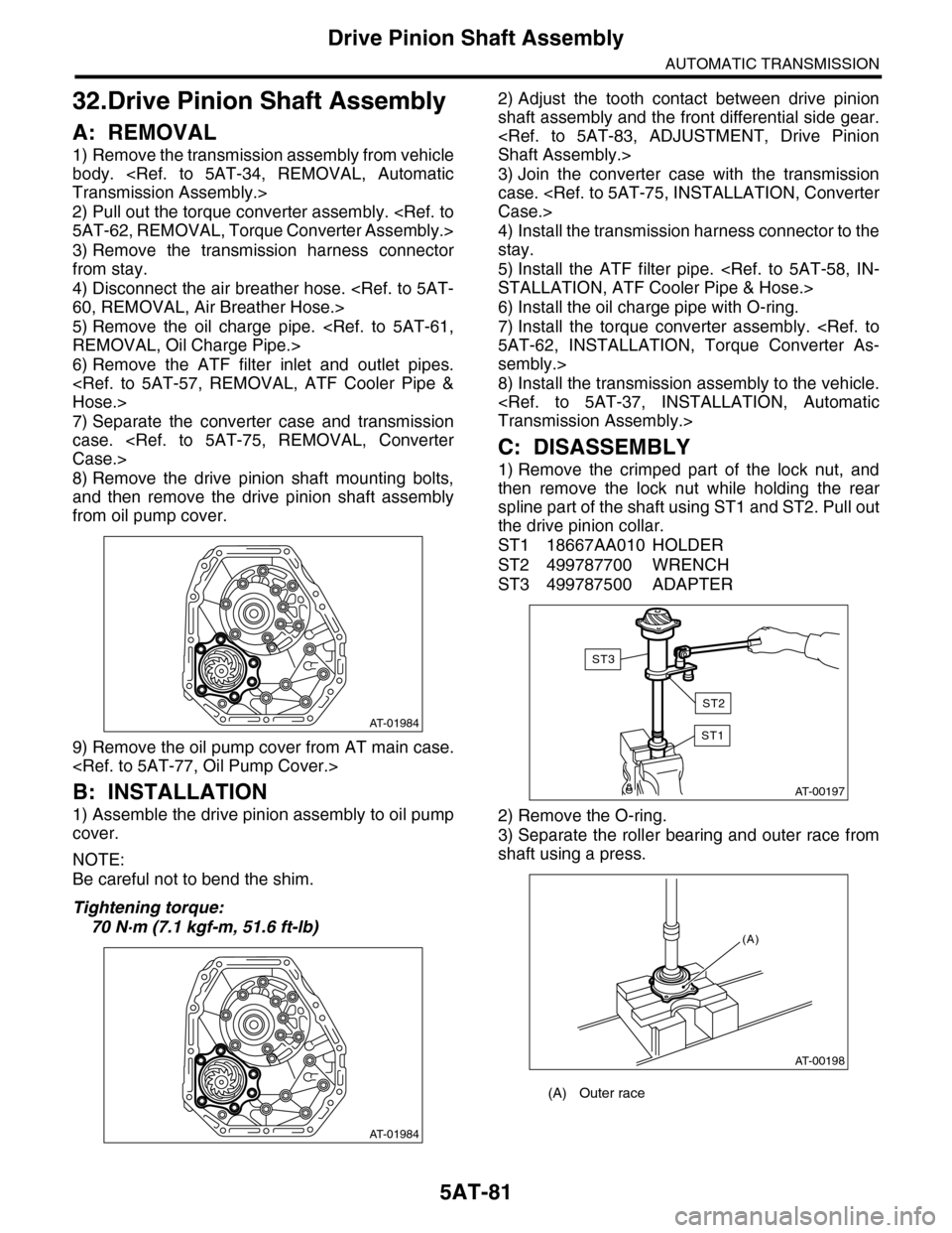
8) Remove the drive pinion shaft mounting bolts,
and then remove the drive pinion shaft assembly
from oil pump cover.
9) Remove the oil pump cover from AT main case.
B: INSTALLATION
1) Assemble the drive pinion assembly to oil pump
cover.
NOTE:
Be careful not to bend the shim.
Tightening torque:
70 N·m (7.1 kgf-m, 51.6 ft-lb)
2) Adjust the tooth contact between drive pinion
shaft assembly and the front differential side gear.
3) Join the converter case with the transmission
case.
4) Install the transmission harness connector to the
stay.
5) Install the ATF filter pipe.
6) Install the oil charge pipe with O-ring.
7) Install the torque converter assembly.
sembly.>
8) Install the transmission assembly to the vehicle.
C: DISASSEMBLY
1) Remove the crimped part of the lock nut, and
then remove the lock nut while holding the rear
spline part of the shaft using ST1 and ST2. Pull out
the drive pinion collar.
ST1 18667AA010 HOLDER
ST2 499787700 WRENCH
ST3 499787500 ADAPTER
2) Remove the O-ring.
3) Separate the roller bearing and outer race from
shaft using a press.
AT-01984
AT-01984
(A) Outer race
AT-00197
ST1
ST3
ST2
AT-00198
(A)
Page 2102 of 2453

5AT-86
Front Differential Assembly
AUTOMATIC TRANSMISSION
33.Front Differential Assembly
A: REMOVAL
1) Remove the transmission assembly from vehicle
body.
2) Pull out the torque converter assembly.
3) Remove the transmission harness connector
from stay.
4) Remove the oil charge pipe.
5) Remove the ATF filter inlet and outlet pipes.
6) Separate the converter case from the transmis-
sion case.
7) Remove the differential side retainers using ST.
NOTE:
Hold the differential case assembly by hand to
avoid damaging the retainer mounting hole of the
converter case.
ST 18630AA010 WRENCH COMPL RETAIN-
ER
8) Remove the differential assembly while being
careful not to damage the attachment part of retain-
er.
B: INSTALLATION
1) When installing the differential assembly to
case, be careful not to damage the inside of case
(particularly, the differential side retainer mating
surface).
2) Install the O-ring to left and right side retainer.
3) Using the ST, install the side retainer.
ST 18630AA010 WRENCH COMPL RETAIN-
ER
4) Adjust the backlash of the front differential.
sembly.>
5) Install the lock plate.
Tightening torque:
25 N·m (2.5 kgf-m, 18 ft-lb)
6) Install the converter case to the transmission
case.
7) Install the transmission harness connector to the
stay.
8) Install the ATF filter pipe.
9) Install the oil charge pipe together with an O-
ring.
10) Install the torque converter assembly.
sembly.>
11) Install the transmission assembly to the vehi-
cle.
C: DISASSEMBLY
1. DIFFERENTIAL CASE ASSEMBLY
1) Remove the taper roller bearing using the ST
and a press.
ST 498077000 REMOVER
(A) Differential ASSY
AT-01987
(A)
(A) Lock plate
AT-01988
(A)
AT-00216
Page 2107 of 2453
5AT-91
AT Main Case
AUTOMATIC TRANSMISSION
34.AT Main Case
A: REMOVAL
1) Remove the transmission assembly from vehicle
body.
2) Pull out the torque converter assembly.
3) Remove the transmission harness connector
from stay.
4) Disconnect the air breather hose.
5) Remove the oil charge pipe.
6) Remove the ATF filter inlet and outlet pipes.
7) Remove the extension case.
8) Remove the center differential carrier.
9) Remove the reduction driven gear.
10) Separate the converter case from the transmis-
sion case.
11) Remove the control valve body.
12) Remove the oil pump cover.
NOTE:
The input clutch pack assembly and front sun gear
assembly are also removed together.
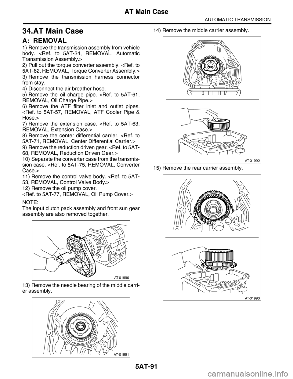
13) Remove the needle bearing of the middle carri-
er assembly.
14) Remove the middle carrier assembly.
15) Remove the rear carrier assembly.
AT-01990
AT-01991
AT-01992
AT-01993
Page 2116 of 2453
5AT-100
Transmission Control Device
AUTOMATIC TRANSMISSION
35.Transmission Control Device
A: REMOVAL
1) Remove the transmission assembly from vehicle
body.
2) Pull out the torque converter assembly.
3) Lift-up the lever on the rear side of transmission
harness connector, and then disconnect it from the
stay.
4) Disconnect the air breather hose.
5) Wrap vinyl tape around the nipple attached to
the air breather hose.
6) Remove the pitching stopper bracket.
7) Remove the control valve body assembly.
8) Pull out the straight pin of manual plate.
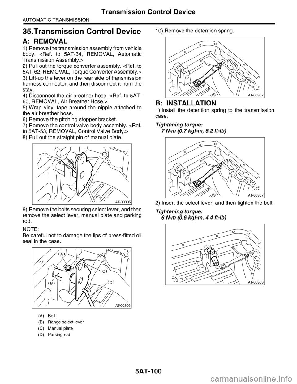
9) Remove the bolts securing select lever, and then
remove the select lever, manual plate and parking
rod.
NOTE:
Be careful not to damage the lips of press-fitted oil
seal in the case.
10) Remove the detention spring.
B: INSTALLATION
1) Install the detention spring to the transmission
case.
Tightening torque:
7 N·m (0.7 kgf-m, 5.2 ft-lb)
2) Insert the select lever, and then tighten the bolt.
Tightening torque:
6 N·m (0.6 kgf-m, 4.4 ft-lb)
(A) Bolt
(B) Range select lever
(C) Manual plate
(D) Parking rod
AT-00305
AT-00306
AT-00307
AT-00307
AT-00308
Page 2122 of 2453
5AT(diag)-5
General Description
AUTOMATIC TRANSMISSION (DIAGNOSTICS)
3. General Description
A: CAUTION
•SRS AIRBAG SYSTEM
The airbag system wiring harness is routed near
the TCM.
CAUTION:
•All air bag system wiring harnesses and con-
nectors are colored yellow. Do not use an elec-
tric test equipment to check these circuits.
•Be careful not to damage the airbag system
wiring harness when performing diagnostics or
servicing the TCM.
•MEASUREMENT
When measuring the voltage and resistance of the
ECM, TCM or each sensor, use a tapered pin with
a diameter of less than 0.64 mm (0.025 in) in order
to avoid poor contact. Do not insert a pin of more
than 0.65 mm (0.026 in) diameter.
B: INSPECTION
1. BATTERY
Measure the battery voltage and specific gravity of
electrolyte.
Standard voltage: 12 V or more
Specific gravity: 1.260 or more
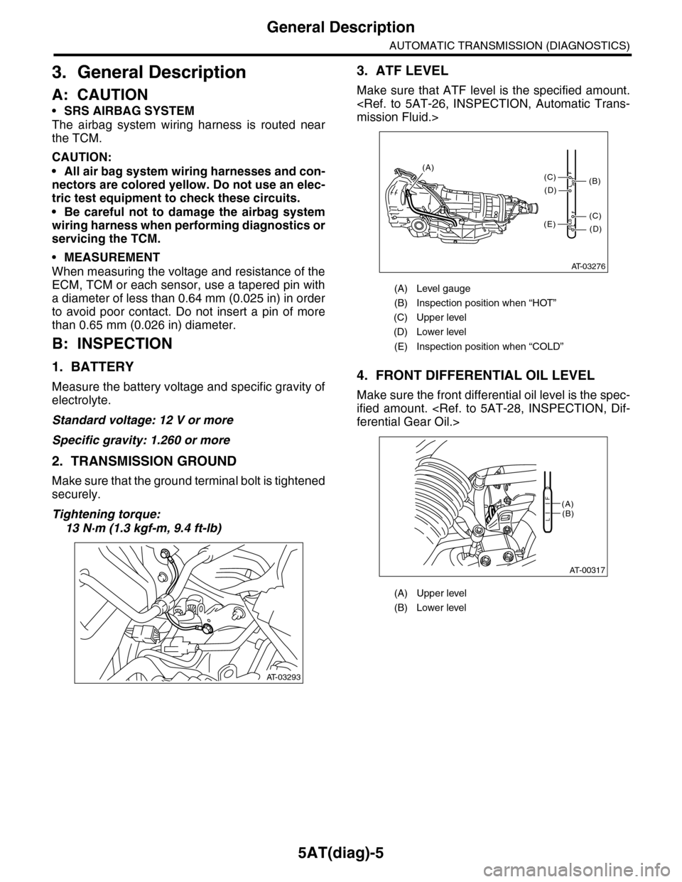
2. TRANSMISSION GROUND
Make sure that the ground terminal bolt is tightened
securely.
Tightening torque:
13 N·m (1.3 kgf-m, 9.4 ft-lb)
3. ATF LEVEL
Make sure that ATF level is the specified amount.
4. FRONT DIFFERENTIAL OIL LEVEL
Make sure the front differential oil level is the spec-
ified amount.
AT-03293
(A) Level gauge
(B) Inspection position when “HOT”
(C) Upper level
(D) Lower level
(E) Inspection position when “COLD”
(A) Upper level
(B) Lower level
AT-03276
COLDLF
HOTLF
(C)
(D)
(C)
(D)
(E)
(B)
(A)
AT-00317
(A)(B)L
F
Page 2142 of 2453
5AT(diag)-25
Diagnostic Procedure for Subaru Select Monitor Communication
AUTOMATIC TRANSMISSION (DIAGNOSTICS)
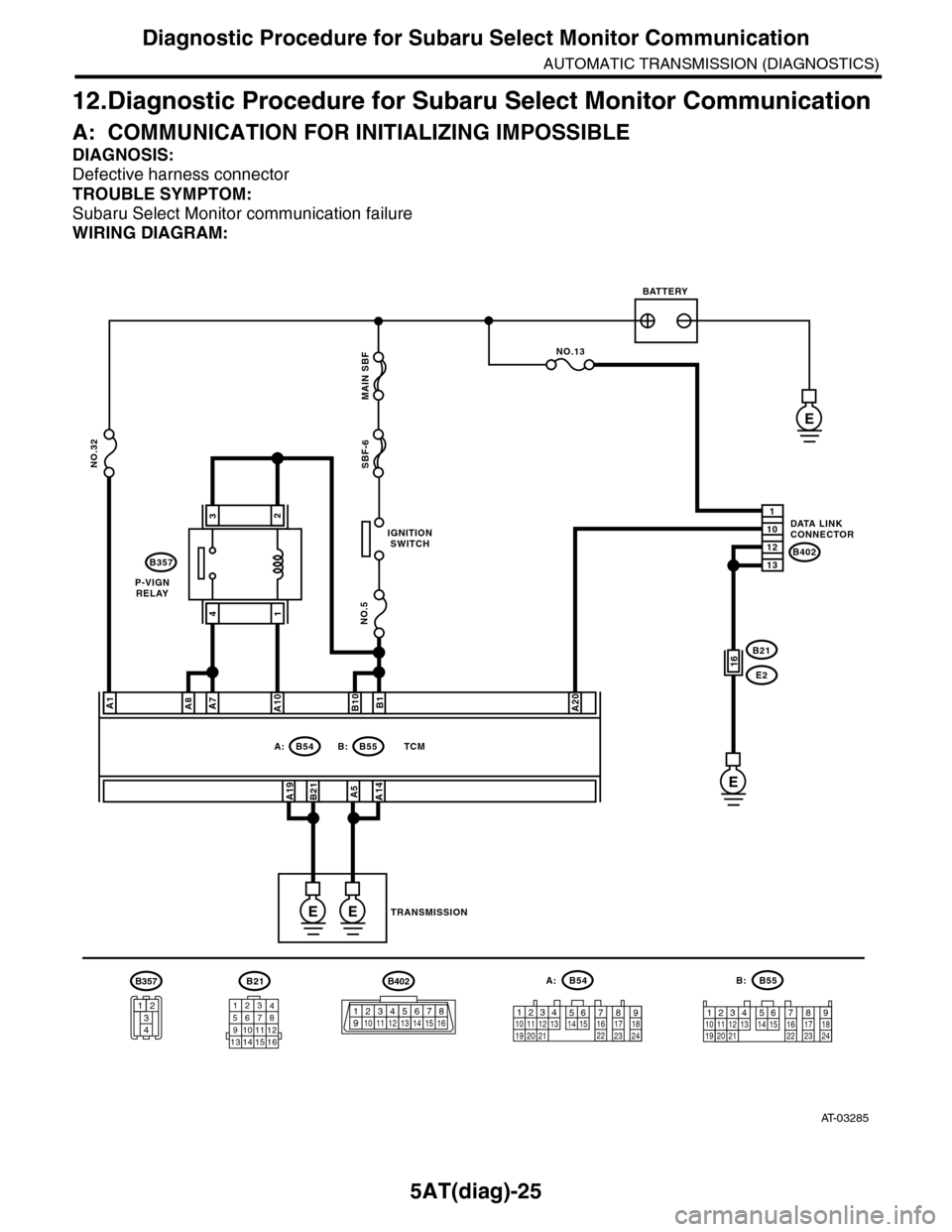
12.Diagnostic Procedure for Subaru Select Monitor Communication
A: COMMUNICATION FOR INITIALIZING IMPOSSIBLE
DIAGNOSIS:
Defective harness connector
TROUBLE SYMPTOM:
Subaru Select Monitor communication failure
WIRING DIAGRAM:
AT-03285
B21
12345678910111213 14 15 16
B54A:
12789563410 11 1219 20 2113 14 15 16 17 18222324
B55B:
12341011 121920 21135614 1578916 17 1822 23 24
IGNITIONSWITCH
P-VIGNRELAY
BATTERY
DATA LINKCONNECTOR
TRANSMISSION
B54A:B55
B357
B: TCM
B402
E
NO.5
NO.32SBF-6 MAIN SBF
A1
A19B21
B1B10A20
A5A14
1
12
10
13
NO.13
B21
E216
E
EE
A7A8A10
32
41
B402
123 8910413 14 15 165671112
B357
34
12
Page 2143 of 2453
5AT(diag)-26
Diagnostic Procedure for Subaru Select Monitor Communication
AUTOMATIC TRANSMISSION (DIAGNOSTICS)
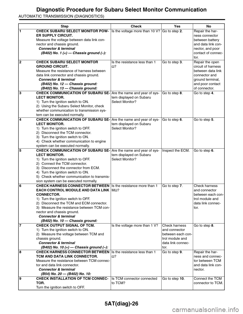
Step Check Yes No
1CHECK SUBARU SELECT MONITOR POW-
ER SUPPLY CIRCUIT.
Measure the voltage between data link con-
nector and chassis ground.
Connector & terminal
(B402) No. 1 (+) — Chassis ground (–):
Is the voltage more than 10 V? Go to step 2.Repair the har-
ness connector
between battery
and data link con-
nector, and poor
contact of connec-
tor.
2CHECK SUBARU SELECT MONITOR
GROUND CIRCUIT.
Measure the resistance of harness between
data link connector and chassis ground.
Connector & terminal
(B402) No. 12 — Chassis ground:
(B402) No. 13 — Chassis ground:
Is the resistance less than 1
Ω?
Go to step 3.Repair the open
circuit of harness
between data link
connector and
ground terminal,
and poor contact
of connector.
3CHECK COMMUNICATION OF SUBARU SE-
LECT MONITOR.
1) Turn the ignition switch to ON.
2) Using the Subaru Select Monitor, check
whether communication to transmission sys-
tem can be executed normally.
Are the name and year of sys-
tem displayed on Subaru
Select Monitor?
Go to step 8.Go to step 4.
4CHECK COMMUNICATION OF SUBARU SE-
LECT MONITOR.
1) Turn the ignition switch to OFF.
2) Disconnect the TCM connector.
3) Turn the ignition switch to ON.
4) Check whether communication to engine
system can be executed normally.
Are the name and year of sys-
tem displayed on Subaru
Select Monitor?
Go to step 6.Go to step 5.
5CHECK COMMUNICATION OF SUBARU SE-
LECT MONITOR.
1) Turn the ignition switch to OFF.
2) Connect the TCM connector.
3) Disconnect the connector from ECM.
4) Turn the ignition switch to ON.
5) Check whether communication to transmis-
sion system can be executed normally.
Are the name and year of sys-
tem displayed on Subaru
Select Monitor?
Inspect the ECM. Go to step 6.
6CHECK HARNESS CONNECTOR BETWEEN
EACH CONTROL MODULE AND DATA LINK
CONNECTOR.
1) Turn the ignition switch to OFF.
2) Disconnect the TCM and ECM connector.
3) Measure the resistance between TCM con-
nector and chassis ground.
Connector & terminal
(B402) No. 10 — Chassis ground:
Is the resistance more than 1
MΩ?
Go to step 7.Check harness
and connector
between each con-
trol module and
data link connec-
tor.
7CHECK OUTPUT SIGNAL OF TCM.
1) Turn the ignition switch to ON.
2) Measure the voltage between TCM and
chassis ground.
Connector & terminal
(B402) No. 10 (+) — Chassis ground (–):
Is the voltage more than 1 V? Check harness
and connector
between each con-
trol module and
data link connec-
tor.
Go to step 8.
8CHECK HARNESS CONNECTOR BETWEEN
TCM AND DATA LINK CONNECTOR.
Measure the resistance between TCM connec-
tor and data link connector.
Connector & terminal
(B54) No. 20 — (B402) No. 10:
Is the resistance less than 1
Ω?
Go to step 9.Repair the har-
ness and connec-
tor between TCM
and data link con-
nector.
9CHECK INSTALLATION OF TCM CONNEC-
TOR.
Tu r n t h e i g n i t i o n s w i t c h t o O F F.
Is TCM connector connected
to TCM?
Go to step 10.Connect the TCM
connector to TCM.