2009 SUBARU TRIBECA Harness
[x] Cancel search: HarnessPage 2171 of 2453
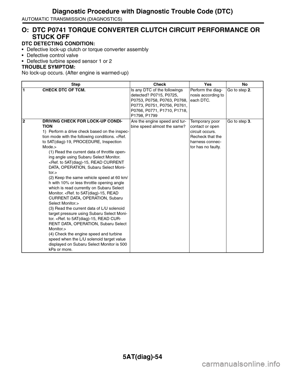
5AT(diag)-54
Diagnostic Procedure with Diagnostic Trouble Code (DTC)
AUTOMATIC TRANSMISSION (DIAGNOSTICS)
O: DTC P0741 TORQUE CONVERTER CLUTCH CIRCUIT PERFORMANCE OR
STUCK OFF
DTC DETECTING CONDITION:
•Defective lock-up clutch or torque converter assembly
•Defective control valve
•Defective turbine speed sensor 1 or 2
TROUBLE SYMPTOM:
No lock-up occurs. (After engine is warmed-up)
Step Check Yes No
1CHECK DTC OF TCM.Is any DTC of the followings
detected? P0715, P0725,
P0753, P0758, P0763, P0768,
P0773, P0751, P0756, P0761,
P0766, P0771, P1710, P1718,
P1798, P1799
Pe r for m t h e d ia g -
nosis according to
each DTC.
Go to step 2.
2DRIVING CHECK FOR LOCK-UP CONDI-
TION
1) Perform a drive check based on the inspec-
tion mode with the following conditions.
Mode.>
(1) Read the current data of throttle open-
ing angle using Subaru Select Monitor.
tor.>
(2) Keep the same vehicle speed at 60 km/
h with 10% or less throttle opening angle
which is read currently on Subaru Select
Monitor.
Select Monitor.>
(3) Read the current data of L/U solenoid
target pressure using Subaru Select Moni-
tor.
Monitor.>
(4) Check the engine speed and turbine
speed when the L/U solenoid target value
displayed on Subaru Select Monitor is 500
kPa or more.
Are the engine speed and tur-
bine speed almost the same?
Te m p o r a r y p o o r
contact or open
circuit occurs.
Recheck that the
harness connec-
tor has no faulty.
Go to step 3.
Page 2172 of 2453
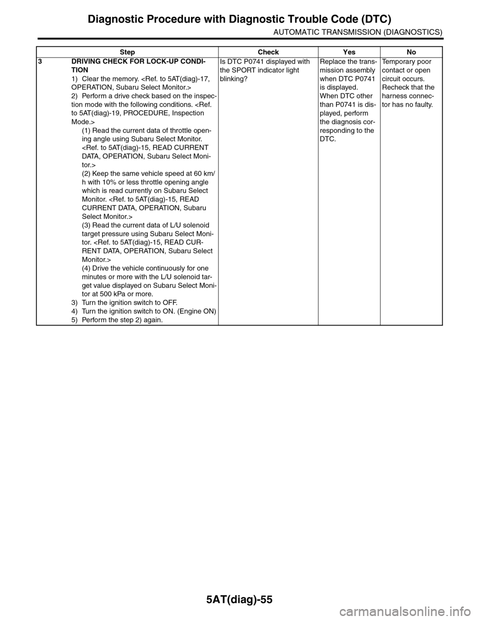
5AT(diag)-55
Diagnostic Procedure with Diagnostic Trouble Code (DTC)
AUTOMATIC TRANSMISSION (DIAGNOSTICS)
3DRIVING CHECK FOR LOCK-UP CONDI-
TION
1) Clear the memory.
2) Perform a drive check based on the inspec-
tion mode with the following conditions.
Mode.>
(1) Read the current data of throttle open-
ing angle using Subaru Select Monitor.
tor.>
(2) Keep the same vehicle speed at 60 km/
h with 10% or less throttle opening angle
which is read currently on Subaru Select
Monitor.
Select Monitor.>
(3) Read the current data of L/U solenoid
target pressure using Subaru Select Moni-
tor.
Monitor.>
(4) Drive the vehicle continuously for one
minutes or more with the L/U solenoid tar-
get value displayed on Subaru Select Moni-
tor at 500 kPa or more.
3) Turn the ignition switch to OFF.
4) Turn the ignition switch to ON. (Engine ON)
5) Perform the step 2) again.
Is DTC P0741 displayed with
the SPORT indicator light
blinking?
Replace the trans-
mission assembly
when DTC P0741
is displayed.
When DTC other
than P0741 is dis-
played, perform
the diagnosis cor-
responding to the
DTC.
Te m p o r a r y p o o r
contact or open
circuit occurs.
Recheck that the
harness connec-
tor has no faulty.
Step Check Yes No
Page 2174 of 2453
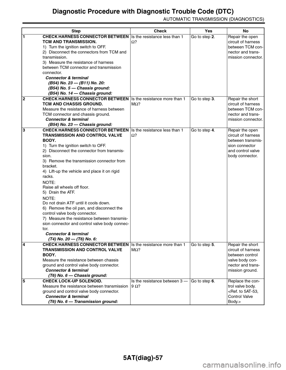
5AT(diag)-57
Diagnostic Procedure with Diagnostic Trouble Code (DTC)
AUTOMATIC TRANSMISSION (DIAGNOSTICS)
Step Check Yes No
1CHECK HARNESS CONNECTOR BETWEEN
TCM AND TRANSMISSION.
1) Turn the ignition switch to OFF.
2) Disconnect the connectors from TCM and
transmission.
3) Measure the resistance of harness
between TCM connector and transmission
connector.
Connector & terminal
(B54) No. 23 — (B11) No. 20:
(B54) No. 5 — Chassis ground:
(B54) No. 14 — Chassis ground:
Is the resistance less than 1
Ω?
Go to step 2.Repair the open
circuit of harness
between TCM con-
nector and trans-
mission connector.
2CHECK HARNESS CONNECTOR BETWEEN
TCM AND CHASSIS GROUND.
Measure the resistance of harness between
TCM connector and chassis ground.
Connector & terminal
(B54) No. 23 — Chassis ground:
Is the resistance more than 1
MΩ?
Go to step 3.Repair the short
circuit of harness
between TCM con-
nector and trans-
mission connector.
3CHECK HARNESS CONNECTOR BETWEEN
TRANSMISSION AND CONTROL VALVE
BODY.
1) Turn the ignition switch to OFF.
2) Disconnect the connector from transmis-
sion.
3) Remove the transmission connector from
bracket.
4) Lift-up the vehicle and place it on rigid
racks.
NOTE:
Raise all wheels off floor.
5) Drain the ATF.
NOTE:Do not drain ATF until it cools down.
6) Remove the oil pan, and disconnect the
control valve body connector.
7) Measure the resistance between transmis-
sion connector and control valve body connec-
tor.
Connector & terminal
(T4) No. 20 — (T6) No. 6:
Is the resistance less than 1
Ω?
Go to step 4.Repair the open
circuit of harness
between transmis-
sion connector
and control valve
body connector.
4CHECK HARNESS CONNECTOR BETWEEN
TRANSMISSION AND CONTROL VALVE
BODY.
Measure the resistance between chassis
ground and control valve body connector.
Connector & terminal
(T6) No. 6 — Chassis ground:
Is the resistance more than 1
MΩ?
Go to step 5.Repair the short
circuit of harness
between control
valve body con-
nector and trans-
mission ground.
5CHECK LOCK-UP SOLENOID.
Measure the resistance between transmission
ground and control valve body connector.
Connector & terminal
(T6) No. 6 — Transmission ground:
Is the resistance between 3 —
9 Ω?
Go to step 6.Replace the con-
trol valve body.
Body.>
Page 2175 of 2453
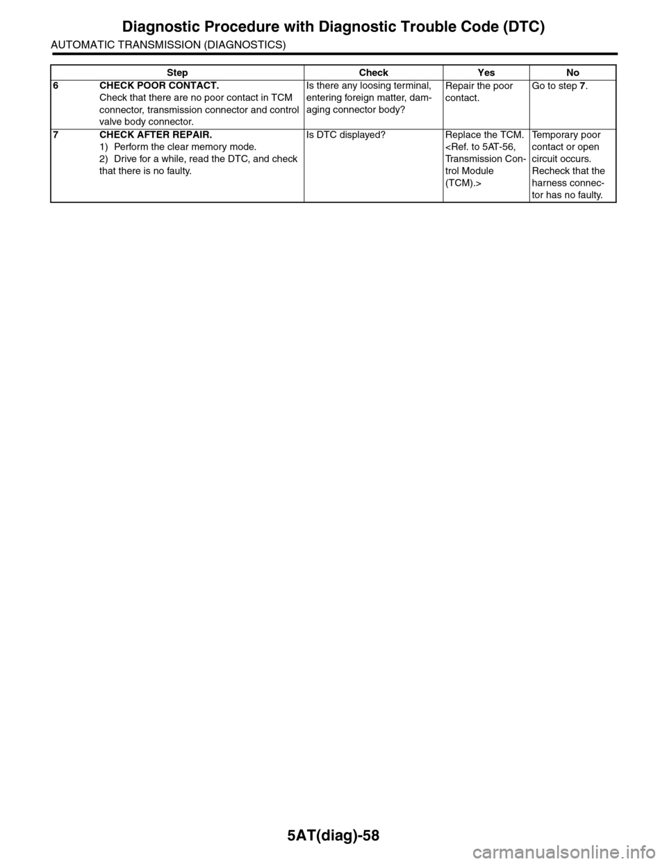
5AT(diag)-58
Diagnostic Procedure with Diagnostic Trouble Code (DTC)
AUTOMATIC TRANSMISSION (DIAGNOSTICS)
6CHECK POOR CONTACT.
Check that there are no poor contact in TCM
connector, transmission connector and control
valve body connector.
Is there any loosing terminal,
entering foreign matter, dam-
aging connector body?
Repair the poor
contact.
Go to step 7.
7CHECK AFTER REPAIR.
1) Perform the clear memory mode.
2) Drive for a while, read the DTC, and check
that there is no faulty.
Is DTC displayed? Replace the TCM.
trol Module
(TCM).>
Te m p o r a r y p o o r
contact or open
circuit occurs.
Recheck that the
harness connec-
tor has no faulty.
Step Check Yes No
Page 2177 of 2453
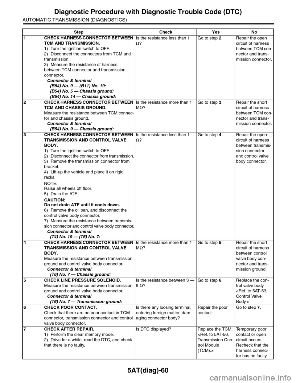
5AT(diag)-60
Diagnostic Procedure with Diagnostic Trouble Code (DTC)
AUTOMATIC TRANSMISSION (DIAGNOSTICS)
Step Check Yes No
1CHECK HARNESS CONNECTOR BETWEEN
TCM AND TRANSMISSION.
1) Turn the ignition switch to OFF.
2) Disconnect the connectors from TCM and
transmission.
3) Measure the resistance of harness
between TCM connector and transmission
connector.
Connector & terminal
(B54) No. 9 — (B11) No. 19:
(B54) No. 5 — Chassis ground:
(B54) No. 14 — Chassis ground:
Is the resistance less than 1
Ω?
Go to step 2.Repair the open
circuit of harness
between TCM con-
nector and trans-
mission connector.
2CHECK HARNESS CONNECTOR BETWEEN
TCM AND CHASSIS GROUND.
Measure the resistance between TCM connec-
tor and chassis ground.
Connector & terminal
(B54) No. 9 — Chassis ground:
Is the resistance more than 1
MΩ?
Go to step 3.Repair the short
circuit of harness
between TCM con-
nector and trans-
mission connector.
3CHECK HARNESS CONNECTOR BETWEEN
TRANSMISSION AND CONTROL VALVE
BODY.
1) Turn the ignition switch to OFF.
2) Disconnect the connector from transmission.
3) Remove the transmission connector from
bracket.
4) Lift-up the vehicle and place it on rigid
racks.
NOTE:Raise all wheels off floor.
5) Drain the ATF.
CAUTION:Do not drain ATF until it cools down.
6) Remove the oil pan, and disconnect the
control valve body connector.
7) Measure the resistance between transmis-
sion connector and control valve body connector.
Connector & terminal
(T4) No. 19 — (T6) No. 7:
Is the resistance less than 1
Ω?
Go to step 4.Repair the open
circuit of harness
between transmis-
sion connector
and control valve
body connector.
4CHECK HARNESS CONNECTOR BETWEEN
TRANSMISSION AND CONTROL VALVE
BODY.
Measure the resistance between transmission
ground and control valve body connector.
Connector & terminal
(T6) No. 7 — Chassis ground:
Is the resistance more than 1
MΩ?
Go to step 5.Repair the short
circuit of harness
between control
valve body con-
nector and trans-
mission ground.
5CHECK LINE PRESSURE SOLENOID.
Measure the resistance between transmission
ground and control valve body connector.
Connector & terminal
(T6) No. 7 — Transmission ground:
Is the resistance between 3 —
9 Ω?
Go to step 6.Replace the con-
trol valve body.
Body.>
6CHECK POOR CONTACT.
Check that there are no poor contact in TCM
connector, transmission connector and control
valve body connector.
Is there any loosing terminal,
entering foreign matter, dam-
aging connector body?
Repair the poor
contact.
Go to step 7.
7CHECK AFTER REPAIR.
1) Perform the clear memory mode.
2) Drive for a while, read the DTC, and check
that there is no faulty.
Is DTC displayed? Replace the TCM.
trol Module
(TCM).>
Te m p o r a r y p o o r
contact or open
circuit occurs.
Recheck that the
harness connec-
tor has no faulty.
Page 2179 of 2453
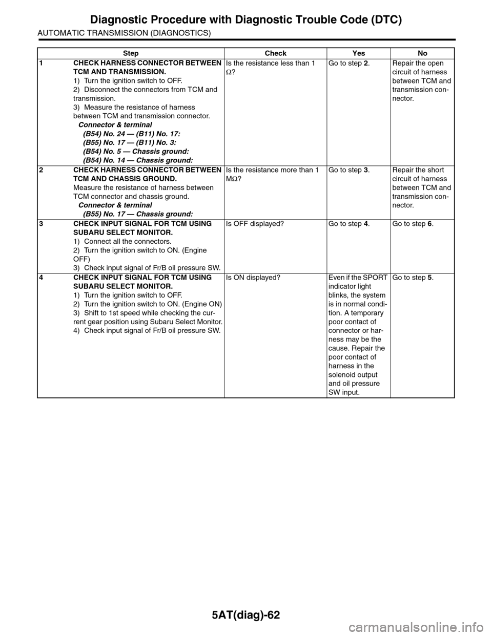
5AT(diag)-62
Diagnostic Procedure with Diagnostic Trouble Code (DTC)
AUTOMATIC TRANSMISSION (DIAGNOSTICS)
Step Check Yes No
1CHECK HARNESS CONNECTOR BETWEEN
TCM AND TRANSMISSION.
1) Turn the ignition switch to OFF.
2) Disconnect the connectors from TCM and
transmission.
3) Measure the resistance of harness
between TCM and transmission connector.
Connector & terminal
(B54) No. 24 — (B11) No. 17:
(B55) No. 17 — (B11) No. 3:
(B54) No. 5 — Chassis ground:
(B54) No. 14 — Chassis ground:
Is the resistance less than 1
Ω?
Go to step 2.Repair the open
circuit of harness
between TCM and
transmission con-
nector.
2CHECK HARNESS CONNECTOR BETWEEN
TCM AND CHASSIS GROUND.
Measure the resistance of harness between
TCM connector and chassis ground.
Connector & terminal
(B55) No. 17 — Chassis ground:
Is the resistance more than 1
MΩ?
Go to step 3.Repair the short
circuit of harness
between TCM and
transmission con-
nector.
3CHECK INPUT SIGNAL FOR TCM USING
SUBARU SELECT MONITOR.
1) Connect all the connectors.
2) Turn the ignition switch to ON. (Engine
OFF)
3) Check input signal of Fr/B oil pressure SW.
Is OFF displayed? Go to step 4.Go to step 6.
4CHECK INPUT SIGNAL FOR TCM USING
SUBARU SELECT MONITOR.
1) Turn the ignition switch to OFF.
2) Turn the ignition switch to ON. (Engine ON)
3) Shift to 1st speed while checking the cur-
rent gear position using Subaru Select Monitor.
4) Check input signal of Fr/B oil pressure SW.
Is ON displayed? Even if the SPORT
indicator light
blinks, the system
is in normal condi-
tion. A temporary
poor contact of
connector or har-
ness may be the
cause. Repair the
poor contact of
harness in the
solenoid output
and oil pressure
SW input.
Go to step 5.
Page 2180 of 2453
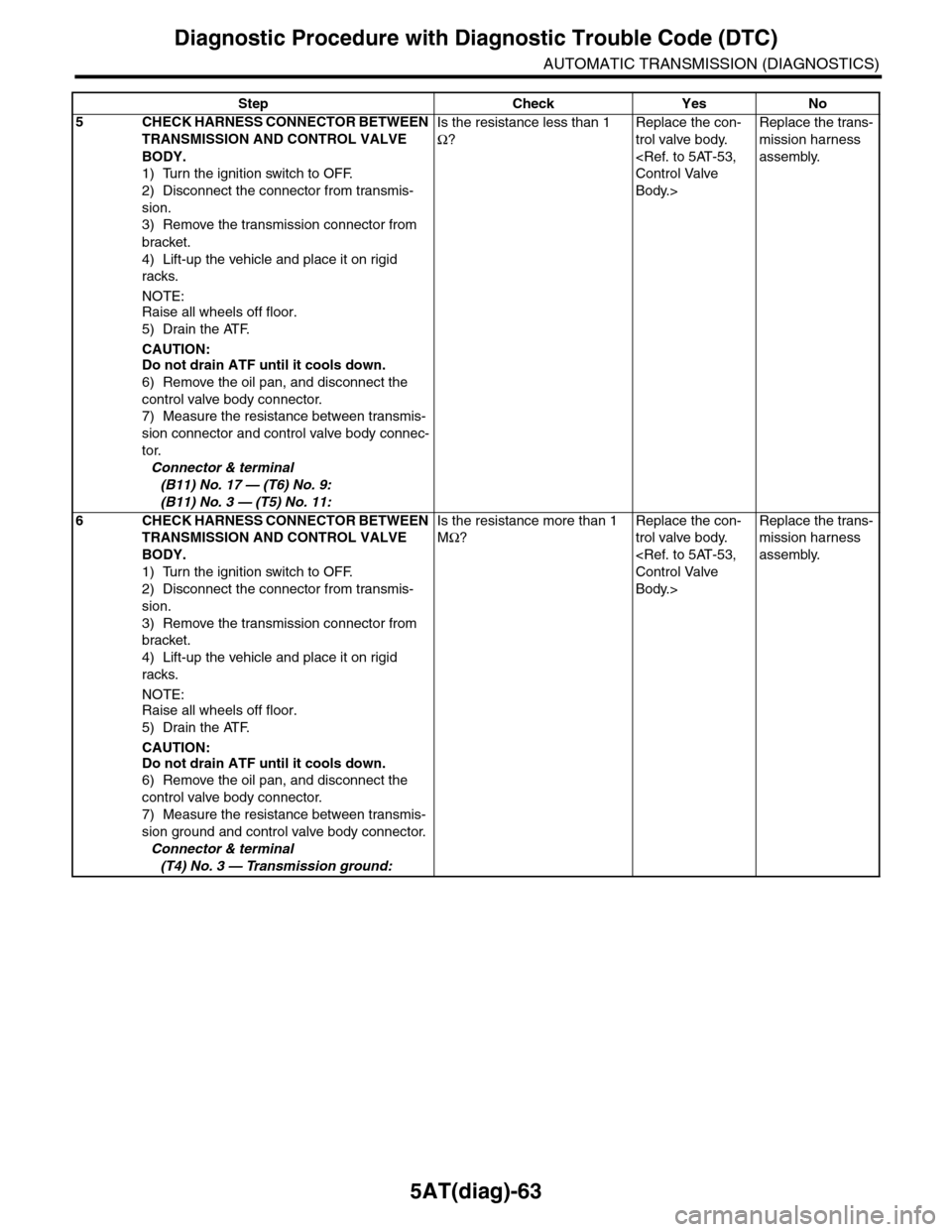
5AT(diag)-63
Diagnostic Procedure with Diagnostic Trouble Code (DTC)
AUTOMATIC TRANSMISSION (DIAGNOSTICS)
5CHECK HARNESS CONNECTOR BETWEEN
TRANSMISSION AND CONTROL VALVE
BODY.
1) Turn the ignition switch to OFF.
2) Disconnect the connector from transmis-
sion.
3) Remove the transmission connector from
bracket.
4) Lift-up the vehicle and place it on rigid
racks.
NOTE:Raise all wheels off floor.
5) Drain the ATF.
CAUTION:Do not drain ATF until it cools down.
6) Remove the oil pan, and disconnect the
control valve body connector.
7) Measure the resistance between transmis-
sion connector and control valve body connec-
tor.
Connector & terminal
(B11) No. 17 — (T6) No. 9:
(B11) No. 3 — (T5) No. 11:
Is the resistance less than 1
Ω?
Replace the con-
trol valve body.
Body.>
Replace the trans-
mission harness
assembly.
6CHECK HARNESS CONNECTOR BETWEEN
TRANSMISSION AND CONTROL VALVE
BODY.
1) Turn the ignition switch to OFF.
2) Disconnect the connector from transmis-
sion.
3) Remove the transmission connector from
bracket.
4) Lift-up the vehicle and place it on rigid
racks.
NOTE:Raise all wheels off floor.
5) Drain the ATF.
CAUTION:
Do not drain ATF until it cools down.
6) Remove the oil pan, and disconnect the
control valve body connector.
7) Measure the resistance between transmis-
sion ground and control valve body connector.
Connector & terminal
(T4) No. 3 — Transmission ground:
Is the resistance more than 1
MΩ?
Replace the con-
trol valve body.
Body.>
Replace the trans-
mission harness
assembly.
Step Check Yes No
Page 2182 of 2453
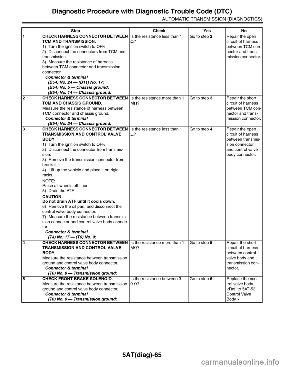
5AT(diag)-65
Diagnostic Procedure with Diagnostic Trouble Code (DTC)
AUTOMATIC TRANSMISSION (DIAGNOSTICS)
Step Check Yes No
1CHECK HARNESS CONNECTOR BETWEEN
TCM AND TRANSMISSION.
1) Turn the ignition switch to OFF.
2) Disconnect the connectors from TCM and
transmission.
3) Measure the resistance of harness
between TCM connector and transmission
connector.
Connector & terminal
(B54) No. 24 — (B11) No. 17:
(B54) No. 5 — Chassis ground:
(B54) No. 14 — Chassis ground:
Is the resistance less than 1
Ω?
Go to step 2.Repair the open
circuit of harness
between TCM con-
nector and trans-
mission connector.
2CHECK HARNESS CONNECTOR BETWEEN
TCM AND CHASSIS GROUND.
Measure the resistance of harness between
TCM connector and chassis ground.
Connector & terminal
(B54) No. 24 — Chassis ground:
Is the resistance more than 1
MΩ?
Go to step 3.Repair the short
circuit of harness
between TCM con-
nector and trans-
mission connector.
3CHECK HARNESS CONNECTOR BETWEEN
TRANSMISSION AND CONTROL VALVE
BODY.
1) Turn the ignition switch to OFF.
2) Disconnect the connector from transmis-
sion.
3) Remove the transmission connector from
bracket.
4) Lift-up the vehicle and place it on rigid
racks.
NOTE:
Raise all wheels off floor.
5) Drain the ATF.
CAUTION:Do not drain ATF until it cools down.
6) Remove the oil pan, and disconnect the
control valve body connector.
7) Measure the resistance between transmis-
sion connector and control valve body connec-
tor.
Connector & terminal
(T4) No. 17 — (T6) No. 9:
Is the resistance less than 1
Ω?
Go to step 4.Repair the open
circuit of harness
between transmis-
sion connector
and control valve
body connector.
4CHECK HARNESS CONNECTOR BETWEEN
TRANSMISSION AND CONTROL VALVE
BODY.
Measure the resistance between transmission
ground and control valve body connector.
Connector & terminal
(T6) No. 9 — Transmission ground:
Is the resistance more than 1
MΩ?
Go to step 5.Repair the short
circuit of harness
between control
valve body and
transmission con-
nector.
5CHECK FRONT BRAKE SOLENOID.
Measure the resistance between transmission
ground and control valve body connector.
Connector & terminal
(T6) No. 9 — Transmission ground:
Is the resistance between 3 —
9 Ω?
Go to step 6.Replace the con-
trol valve body.
Body.>