2009 SUBARU TRIBECA turn signal
[x] Cancel search: turn signalPage 662 of 2453

SL-33
Security System
SECURITY AND LOCKS
8. CHECK HAZARD LIGHT OPERATION
9. CHECK IGNITION SWITCH CIRCUIT
Step Check Yes No
1CHECK HAZARD LIGHT OPERATION.
Make sure the hazard light blinks when hazard
switch is turned to ON.
Does the hazard light blink? Go to step 2.Check the hazard
light circuit.
2CHECK OUTPUT TO HAZARD LIGHT.
1) Turn the ignition switch to OFF.
2) Disconnect the key warning switch harness
connector.
3) Connect the Subaru Select Monitor to data
link connector.
4) Turn the ignition switch to ON.
5) Select {Integ. unit} from main menu.
6) Select {ECM customizing}.
7) Check the {Hazard answer-back setup},
and then switch to ON setting.
8) Select the {Current Data Display & Save}.
9) Check the hazard output signal of body
integrated unit when operating the LOCK/
UNLOCK button of transmitter.
Is output signal is present
when operating the transmitter
LOCK/UNLOCK button?
Go to step 3.Check the body
integrated unit.
Diagnostic Proce-
dure.>
3CHECK CIRCUIT OF HAZARD LIGHT.
1) Turn the ignition switch to OFF.
2) Disconnect the harness connector of body
integrated unit.
3) Disconnect the turn signal & hazard unit
harness connector.
4) Measure the resistance between harness
connector terminals.
Connector & terminal
(B280) No. 12 — (B32) No. 8:
Is the resistance less than 10
Ω?
Check the body
integrated unit.
Diagnostic Proce-
dure.>
Repair the har-
ness.
Step Check Yes No
1CHECK IGNITION SWITCH VOLTAGE.
1) Connect the Subaru Select Monitor to data
link connector.
2) Turn the ignition switch to ON.
3) Select {Integ. unit} from main menu.
4) Select the {Current Data Display & Save}.
5) Check the {BATT voltage} and {IG power
supply}.
Is the {IG power supply} within
±1 V against {BATT voltage}?
The ignition switch
input circuit is OK.
Go to step 2.
2 CHECK IGNITION SWITCH CIRCUIT.
1) Turn the ignition switch to OFF.
2) Disconnect the harness connector of body
integrated unit.
3) Turn the ignition switch to ON.
4) Measure the voltage between harness con-
nector terminal and chassis ground.
Connector & terminal
(i84) No. 1 (+) — Chassis ground (–):
Is the voltage more than 10 V? Check the body
integrated unit.
Diagnostic Proce-
dure.>
Check the harness
for an open or
short circuit
between the body
integrated unit and
fuse.
Page 702 of 2453

WW-7
Combination Switch (Wiper)
WIPER AND WASHER SYSTEMS
2. FRONT WIPER
1) Check with Subaru Select Monitor
2) Check the intermittent operation (inspection of
the wiper switch alone)
(1) Set the voltage meter between connector
terminal No. 7 (+) and No. 2 (–).
(2) Connect the battery between connector ter-
minal No. 7 (+) and No. 2 (–).
(3) Turn the wiper switch to INT.
(4) Connect the battery ground terminal to the
connector terminal No. 16 for five seconds.
(5) After connecting the battery ground terminal
for five seconds in step (4), connect the battery
positive terminal to the connector terminal No.
16 for five seconds.
(6) After connecting the battery ground terminal
and the battery positive terminal to the connec-
tor terminal No. 16 for five seconds each in step
(4) and (5), connect the ground terminal to the
connector terminal No. 16 again.
(7) Perform the step (1) to (6) above at MIN and
MAX position of the intermittent control switch.
If operation is not as specification, replace the
wiper switch assembly.
3) Inspect the vehicle speed response (With the
wiper switch installed on the vehicle)
(1) Operational check
Position the front wiper switch to INT, then mea-
sure the intermittent stationary time at each ve-
hicle speed.
If operation is not as specified, replace the
switch.
(2) CHECK VEHICLE SPEED SIGNAL.
Raise the vehicle speed to more than 10 km/h
(6 mph), then measure the voltage between the
wiper switch connector and the chassis ground.
Terminals
No. 15 (+) — Chassis ground (–):
Step Check Yes No
1CHECK INPUT SIGNAL TO THE BODY INTE-
GRATED UNIT.
When the front wiper switch is operated, check
the input signal using the Subaru Select Moni-
tor.
1) Connect the Subaru Select Monitor to data
link connector.
2) Turn the ignition switch to ON.
3) Select {Integ. unit} from main menu.
4) Select the {Current Data Display & Save}.
5) Check the input signal when the front wiper
switch is set to LO or HI.
Is the input signal normal? Finish the diagno-
sis.
Replace the body
integrated unit.
Unit.>
S: Intermittent down-
time (sec.)
(A): Connect battery ter-
minal to No. 16 in
Step (4).
Intermittent stationary time
specification
MIN: Approx. 4 seconds
MAX: Approx. 21seconds
Switch positionVe h i c l e s p e e d
(km/h (MPH))
Intermittent
stationary time
(sec.)
MIN.
0 (0) Approx. 4
30 (19) Approx. 1.5
60 (37) Approx. 1
MAX.
0 (0) Approx. 21
30 (19) Approx. 19.5
60 (37) Approx. 18
Check Yes No
Does the voltage repeat
12 V and 0 V?
Ve h i c l e s p e e d
signal is nor-
mal.
Replace the
wiper switch.
Page 703 of 2453

WW-8
Combination Switch (Wiper)
WIPER AND WASHER SYSTEMS
(3) CHECK THE VEHICLE SPEED SIGNAL
HARNESS.
Measure the resistance between the wiper
switch connector and the VDC control module.
Terminals
Wiper switch connector No. 15 — VDC con-
trol module No. 33:
3. REAR WIPER
1) Check with Subaru Select Monitor
Check Yes No
Is the resistance 0 Ω?Replace the
wiper switch.
Repair the har-
ness.
Step Check Yes No
1 CHECK INPUT OF REAR WIPER SWITCH.
Check the input from body integrated unit
using the Subaru Select Monitor.
1) Connect the Subaru Select Monitor to data
link connector.
2) Turn the ignition switch to ON.
3) Select {Integ. unit} from main menu.
4) Select the {Current Data Display & Save}.
5) Check the input of the rear wiper switch.
Is the input normal? Go to step 2.Check the rear
wiper switch.
INSPECTION,
Combination
Switch (Wiper).>
2CHECK OUTPUT OF BODY INTEGRATED
UNIT.
When the rear wiper switch is operated, check
the output using the Subaru Select Monitor.
1) Turn the ignition switch to ON.
2) Operate the rear wiper switch and set to
each position of ON and INT.
3) At this time, check the body integrated unit
output.
When set to ON, is ON output
continuous? When set to INT,
is ON/OFF output repeated?
(INT OFF time (when vehicle
parked): 12 seconds)
Check the rear
wiper motor.
INSPECTION,
Rear Wiper
Motor.>
Replace the body
integrated unit.
Unit.>
Page 956 of 2453

TPM(diag)-6
Control Module I/O Signal
TIRE PRESSURE MONITORING SYSTEM (DIAGNOSTICS)
4. Control Module I/O Signal
A: ELECTRICAL SPECIFICATION
Te r m i n a l
No.Measured value Measuring condition Remarks
1Select monitor communication Serial communication —
2Tire pressure warning light output When malfunction occurs, or tire pres-
sure decreases
System failure: blinks
Tire pressure decreases: turns on
4Speed sensor signal While driving (Pulse signal) Change according to vehicle
speed
5Ignition power supply IG switch ON (Battery voltage) —
6Battery power supply Battery voltage Always
8Body integrated unit (Hazard output
signal).—When hazard turns on.
9GND 0 V (Always) Always
Page 962 of 2453

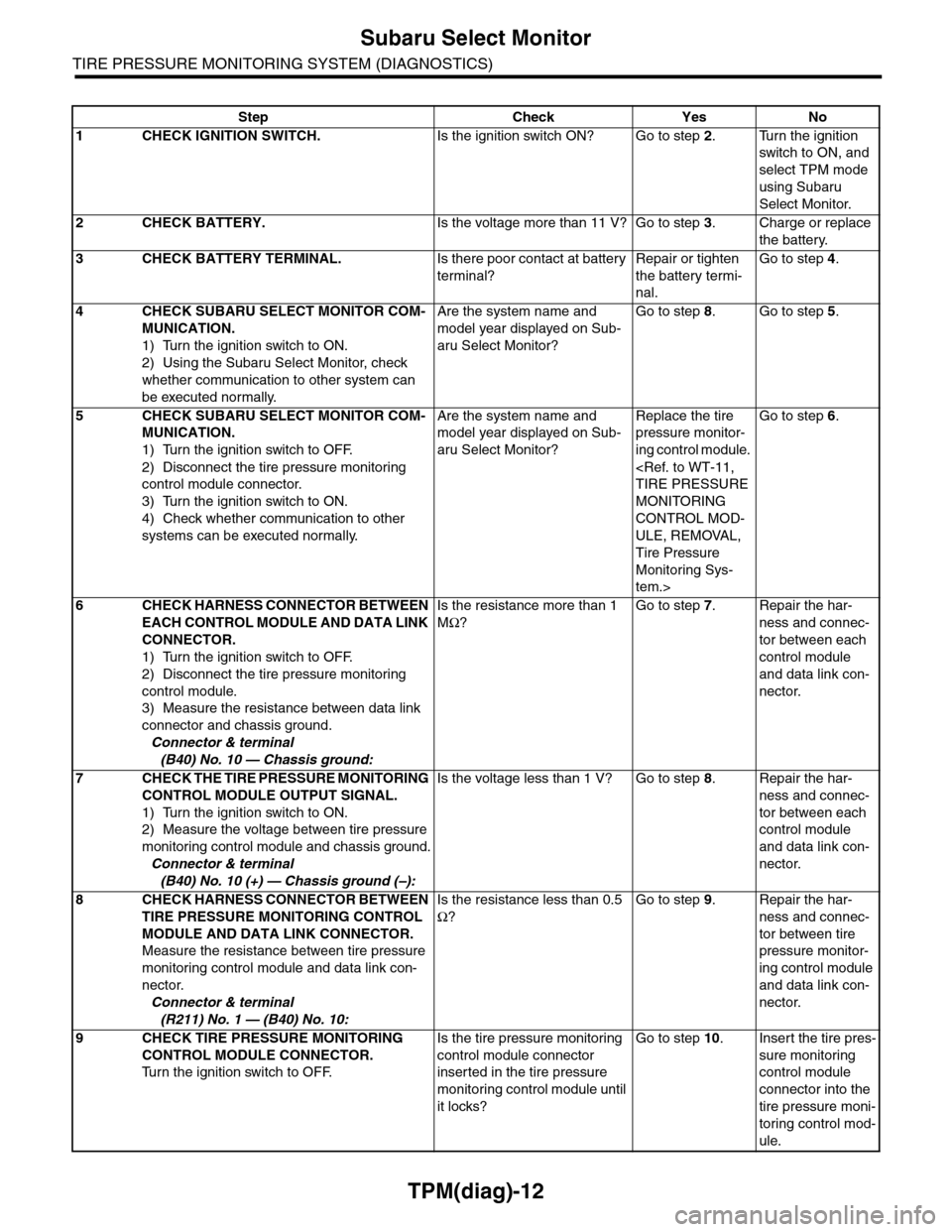
TPM(diag)-12
Subaru Select Monitor
TIRE PRESSURE MONITORING SYSTEM (DIAGNOSTICS)
Step Check Yes No
1CHECK IGNITION SWITCH.Is the ignition switch ON? Go to step 2.Turn the ignition
switch to ON, and
select TPM mode
using Subaru
Select Monitor.
2CHECK BATTERY.Is the voltage more than 11 V? Go to step 3.Charge or replace
the battery.
3CHECK BATTERY TERMINAL.Is there poor contact at battery
terminal?
Repair or tighten
the battery termi-
nal.
Go to step 4.
4CHECK SUBARU SELECT MONITOR COM-
MUNICATION.
1) Turn the ignition switch to ON.
2) Using the Subaru Select Monitor, check
whether communication to other system can
be executed normally.
Are the system name and
model year displayed on Sub-
aru Select Monitor?
Go to step 8.Go to step 5.
5CHECK SUBARU SELECT MONITOR COM-
MUNICATION.
1) Turn the ignition switch to OFF.
2) Disconnect the tire pressure monitoring
control module connector.
3) Turn the ignition switch to ON.
4) Check whether communication to other
systems can be executed normally.
Are the system name and
model year displayed on Sub-
aru Select Monitor?
Replace the tire
pressure monitor-
ing control module.
MONITORING
CONTROL MOD-
ULE, REMOVAL,
Tire Pressure
Monitoring Sys-
tem.>
Go to step 6.
6CHECK HARNESS CONNECTOR BETWEEN
EACH CONTROL MODULE AND DATA LINK
CONNECTOR.
1) Turn the ignition switch to OFF.
2) Disconnect the tire pressure monitoring
control module.
3) Measure the resistance between data link
connector and chassis ground.
Connector & terminal
(B40) No. 10 — Chassis ground:
Is the resistance more than 1
MΩ?
Go to step 7.Repair the har-
ness and connec-
tor between each
control module
and data link con-
nector.
7CHECK THE TIRE PRESSURE MONITORING
CONTROL MODULE OUTPUT SIGNAL.
1) Turn the ignition switch to ON.
2) Measure the voltage between tire pressure
monitoring control module and chassis ground.
Connector & terminal
(B40) No. 10 (+) — Chassis ground (–):
Is the voltage less than 1 V? Go to step 8.Repair the har-
ness and connec-
tor between each
control module
and data link con-
nector.
8CHECK HARNESS CONNECTOR BETWEEN
TIRE PRESSURE MONITORING CONTROL
MODULE AND DATA LINK CONNECTOR.
Measure the resistance between tire pressure
monitoring control module and data link con-
nector.
Connector & terminal
(R211) No. 1 — (B40) No. 10:
Is the resistance less than 0.5
Ω?
Go to step 9.Repair the har-
ness and connec-
tor between tire
pressure monitor-
ing control module
and data link con-
nector.
9CHECK TIRE PRESSURE MONITORING
CONTROL MODULE CONNECTOR.
Tu r n t h e i g n i t i o n s w i t c h t o O F F.
Is the tire pressure monitoring
control module connector
inserted in the tire pressure
monitoring control module until
it locks?
Go to step 10.Insert the tire pres-
sure monitoring
control module
connector into the
tire pressure moni-
toring control mod-
ule.
Page 1006 of 2453

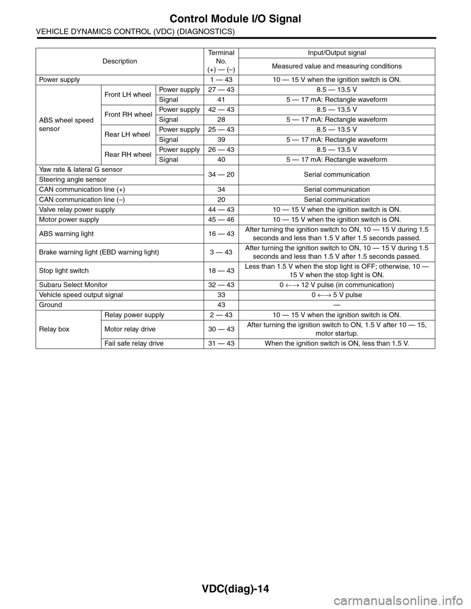
VDC(diag)-14
Control Module I/O Signal
VEHICLE DYNAMICS CONTROL (VDC) (DIAGNOSTICS)
Description
Te r m i n a l
No.
(+) — (–)
Input/Output signal
Measured value and measuring conditions
Pow er s up p ly 1 — 43 10 — 15 V w h e n t h e i gn i t io n sw it ch i s ON .
ABS wheel speed
sensor
Front LH wheelPowe r s u pp ly 27 — 4 3 8 . 5 — 1 3. 5 V
Signal 41 5 — 17 mA: Rectangle waveform
Front RH wheelPower supply 42 — 43 8.5 — 13.5 V
Signal 28 5 — 17 mA: Rectangle waveform
Rear LH wheelPower supply 25 — 43 8.5 — 13.5 V
Signal 39 5 — 17 mA: Rectangle waveform
Rear RH wheelPower supply 26 — 43 8.5 — 13.5 V
Signal 40 5 — 17 mA: Rectangle waveform
Ya w r a t e & l a t e r a l G s e n s o r34 — 20 Serial communicationSteering angle sensor
CAN communication line (+) 34 Serial communication
CAN communication line (–) 20 Serial communication
Valve relay power supply 44 — 43 10 — 15 V when the ignition switch is ON.
Motor power supply 45 — 46 10 — 15 V when the ignition switch is ON.
ABS warning light 16 — 43After turning the ignition switch to ON, 10 — 15 V during 1.5
seconds and less than 1.5 V after 1.5 seconds passed.
Brake warning light (EBD warning light) 3 — 43After turning the ignition switch to ON, 10 — 15 V during 1.5
seconds and less than 1.5 V after 1.5 seconds passed.
Stop light switch 18 — 43Less than 1.5 V when the stop light is OFF; otherwise, 10 —
15 V when the stop light is ON.
Subaru Select Monitor 32 — 43 0 ←→ 12 V pulse (in communication)
Ve h i c l e s p e e d o u t p u t s i g n a l 3 3 0 ←→ 5 V pulse
Ground 43 —
Relay box
Relay power supply 2 — 43 10 — 15 V when the ignition switch is ON.
Motor relay drive 30 — 43After turning the ignition switch to ON, 1.5 V after 10 — 15,
motor startup.
Fa i l s afe r e lay d r ive 31 — 4 3 W he n t h e i g ni t io n swit c h i s ON, l es s t ha n 1 . 5 V.
Page 1036 of 2453

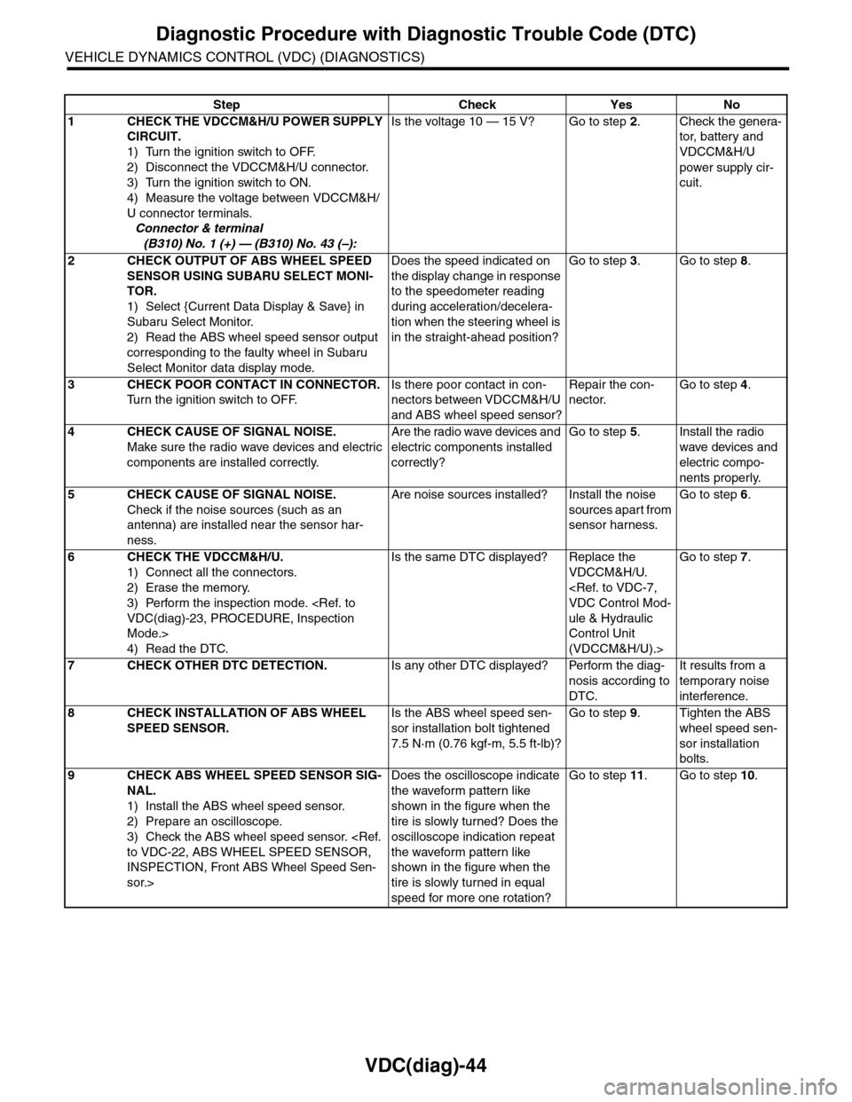
VDC(diag)-44
Diagnostic Procedure with Diagnostic Trouble Code (DTC)
VEHICLE DYNAMICS CONTROL (VDC) (DIAGNOSTICS)
Step Check Yes No
1CHECK THE VDCCM&H/U POWER SUPPLY
CIRCUIT.
1) Turn the ignition switch to OFF.
2) Disconnect the VDCCM&H/U connector.
3) Turn the ignition switch to ON.
4) Measure the voltage between VDCCM&H/
U connector terminals.
Connector & terminal
(B310) No. 1 (+) — (B310) No. 43 (–):
Is the voltage 10 — 15 V? Go to step 2.Check the genera-
tor, batter y and
VDCCM&H/U
power supply cir-
cuit.
2CHECK OUTPUT OF ABS WHEEL SPEED
SENSOR USING SUBARU SELECT MONI-
TOR.
1) Select {Current Data Display & Save} in
Subaru Select Monitor.
2) Read the ABS wheel speed sensor output
corresponding to the faulty wheel in Subaru
Select Monitor data display mode.
Does the speed indicated on
the display change in response
to the speedometer reading
during acceleration/decelera-
tion when the steering wheel is
in the straight-ahead position?
Go to step 3.Go to step 8.
3CHECK POOR CONTACT IN CONNECTOR.
Tu r n t h e i g n i t i o n s w i t c h t o O F F.
Is there poor contact in con-
nectors between VDCCM&H/U
and ABS wheel speed sensor?
Repair the con-
nector.
Go to step 4.
4CHECK CAUSE OF SIGNAL NOISE.
Make sure the radio wave devices and electric
components are installed correctly.
Are the radio wave devices and
electric components installed
correctly?
Go to step 5.Install the radio
wave devices and
electric compo-
nents properly.
5CHECK CAUSE OF SIGNAL NOISE.
Check if the noise sources (such as an
antenna) are installed near the sensor har-
ness.
Are noise sources installed? Install the noise
sources apart from
sensor harness.
Go to step 6.
6CHECK THE VDCCM&H/U.
1) Connect all the connectors.
2) Erase the memory.
3) Perform the inspection mode.
Mode.>
4) Read the DTC.
Is the same DTC displayed? Replace the
VDCCM&H/U.
ule & Hydraulic
Control Unit
(VDCCM&H/U).>
Go to step 7.
7CHECK OTHER DTC DETECTION.Is any other DTC displayed? Perform the diag-
nosis according to
DTC.
It results from a
temporary noise
interference.
8CHECK INSTALLATION OF ABS WHEEL
SPEED SENSOR.
Is the ABS wheel speed sen-
sor installation bolt tightened
7.5 N·m (0.76 kgf-m, 5.5 ft-lb)?
Go to step 9.Tighten the ABS
wheel speed sen-
sor installation
bolts.
9CHECK ABS WHEEL SPEED SENSOR SIG-
NAL.
1) Install the ABS wheel speed sensor.
2) Prepare an oscilloscope.
3) Check the ABS wheel speed sensor.
INSPECTION, Front ABS Wheel Speed Sen-
sor.>
Does the oscilloscope indicate
the waveform pattern like
shown in the figure when the
tire is slowly turned? Does the
oscilloscope indication repeat
the waveform pattern like
shown in the figure when the
tire is slowly turned in equal
speed for more one rotation?
Go to step 11.Go to step 10.
Page 1037 of 2453

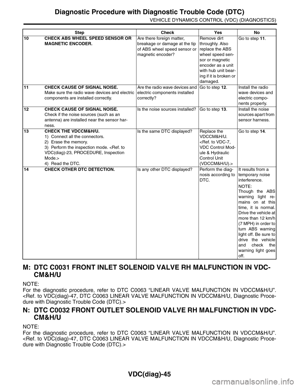
VDC(diag)-45
Diagnostic Procedure with Diagnostic Trouble Code (DTC)
VEHICLE DYNAMICS CONTROL (VDC) (DIAGNOSTICS)
M: DTC C0031 FRONT INLET SOLENOID VALVE RH MALFUNCTION IN VDC-
CM&H/U
NOTE:
For the diagnostic procedure, refer to DTC C0063 “LINEAR VALVE MALFUNCTION IN VDCCM&H/U”.
N: DTC C0032 FRONT OUTLET SOLENOID VALVE RH MALFUNCTION IN VDC-
CM&H/U
NOTE:
For the diagnostic procedure, refer to DTC C0063 “LINEAR VALVE MALFUNCTION IN VDCCM&H/U”.
10 CHECK ABS WHEEL SPEED SENSOR OR
MAGNETIC ENCODER.
Are there foreign matter,
breakage or damage at the tip
of ABS wheel speed sensor or
magnetic encoder?
Remove dirt
throughly. Also
replace the ABS
wheel speed sen-
sor or magnetic
encoder as a unit
with hub unit bear-
ing if it is broken or
damaged.
Go to step 11.
11 CHECK CAUSE OF SIGNAL NOISE.
Make sure the radio wave devices and electric
components are installed correctly.
Are the radio wave devices and
electric components installed
correctly?
Go to step 12.Install the radio
wave devices and
electric compo-
nents properly.
12 CHECK CAUSE OF SIGNAL NOISE.
Check if the noise sources (such as an
antenna) are installed near the sensor har-
ness.
Is the noise sources installed? Go to step 13.Install the noise
sources apart from
sensor harness.
13 CHECK THE VDCCM&H/U.
1) Connect all the connectors.
2) Erase the memory.
3) Perform the inspection mode.
Mode.>
4) Read the DTC.
Is the same DTC displayed? Replace the
VDCCM&H/U.
ule & Hydraulic
Control Unit
(VDCCM&H/U).>
Go to step 14.
14 CHECK OTHER DTC DETECTION.Is any other DTC displayed? Perform the diag-
nosis according to
DTC.
It results from a
temporary noise
interference.
NOTE:
Though the ABS
warning light re-
mains on at this
time, it is normal.
Drive the vehicle at
more than 12 km/h
(7 MPH) in order to
turn ABS warning
light off. Be sure to
drive the vehicle
and check the
warning light goes
off.
Step Check Yes No