2009 SUBARU TRIBECA turn signal
[x] Cancel search: turn signalPage 1069 of 2453
VDC(diag)-77
Diagnostic Procedure with Diagnostic Trouble Code (DTC)
VEHICLE DYNAMICS CONTROL (VDC) (DIAGNOSTICS)
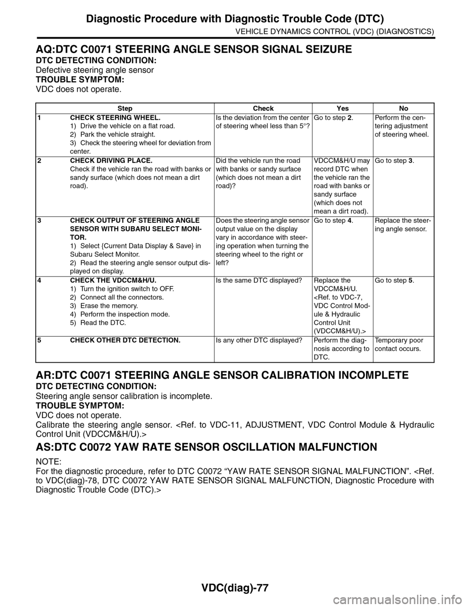
AQ:DTC C0071 STEERING ANGLE SENSOR SIGNAL SEIZURE
DTC DETECTING CONDITION:
Defective steering angle sensor
TROUBLE SYMPTOM:
VDC does not operate.
AR:DTC C0071 STEERING ANGLE SENSOR CALIBRATION INCOMPLETE
DTC DETECTING CONDITION:
Steering angle sensor calibration is incomplete.
TROUBLE SYMPTOM:
VDC does not operate.
Calibrate the steering angle sensor.
AS:DTC C0072 YAW RATE SENSOR OSCILLATION MALFUNCTION
NOTE:
For the diagnostic procedure, refer to DTC C0072 “YAW RATE SENSOR SIGNAL MALFUNCTION”.
Diagnostic Trouble Code (DTC).>
Step Check Yes No
1CHECK STEERING WHEEL.
1) Drive the vehicle on a flat road.
2) Park the vehicle straight.
3) Check the steering wheel for deviation from
center.
Is the deviation from the center
of steering wheel less than 5°?
Go to step 2.Perform the cen-
tering adjustment
of steering wheel.
2CHECK DRIVING PLACE.
Check if the vehicle ran the road with banks or
sandy surface (which does not mean a dirt
road).
Did the vehicle run the road
with banks or sandy surface
(which does not mean a dirt
road)?
VDCCM&H/U may
record DTC when
the vehicle ran the
road with banks or
sandy surface
(which does not
mean a dirt road).
Go to step 3.
3CHECK OUTPUT OF STEERING ANGLE
SENSOR WITH SUBARU SELECT MONI-
TOR.
1) Select {Current Data Display & Save} in
Subaru Select Monitor.
2) Read the steering angle sensor output dis-
played on display.
Does the steering angle sensor
output value on the display
var y in accordance with steer-
ing operation when turning the
steering wheel to the right or
left?
Go to step 4.Replace the steer-
ing angle sensor.
4CHECK THE VDCCM&H/U.
1) Turn the ignition switch to OFF.
2) Connect all the connectors.
3) Erase the memory.
4) Perform the inspection mode.
5) Read the DTC.
Is the same DTC displayed? Replace the
VDCCM&H/U.
ule & Hydraulic
Control Unit
(VDCCM&H/U).>
Go to step 5.
5CHECK OTHER DTC DETECTION.Is any other DTC displayed? Perform the diag-
nosis according to
DTC.
Te m p o r a r y p o o r
contact occurs.
Page 1070 of 2453
VDC(diag)-78
Diagnostic Procedure with Diagnostic Trouble Code (DTC)
VEHICLE DYNAMICS CONTROL (VDC) (DIAGNOSTICS)
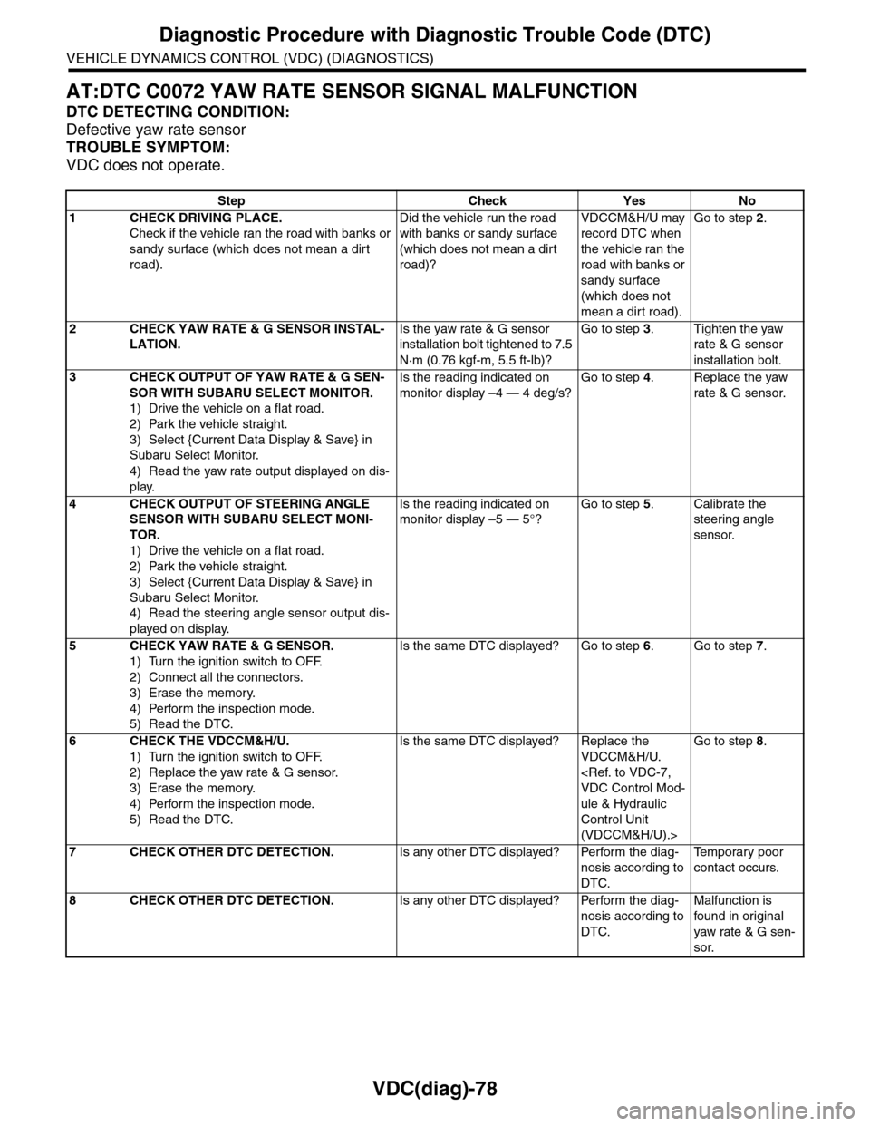
AT:DTC C0072 YAW RATE SENSOR SIGNAL MALFUNCTION
DTC DETECTING CONDITION:
Defective yaw rate sensor
TROUBLE SYMPTOM:
VDC does not operate.
Step Check Yes No
1CHECK DRIVING PLACE.
Check if the vehicle ran the road with banks or
sandy surface (which does not mean a dirt
road).
Did the vehicle run the road
with banks or sandy surface
(which does not mean a dirt
road)?
VDCCM&H/U may
record DTC when
the vehicle ran the
road with banks or
sandy surface
(which does not
mean a dirt road).
Go to step 2.
2CHECK YAW RATE & G SENSOR INSTAL-
LATION.
Is the yaw rate & G sensor
installation bolt tightened to 7.5
N·m (0.76 kgf-m, 5.5 ft-lb)?
Go to step 3.Tighten the yaw
rate & G sensor
installation bolt.
3CHECK OUTPUT OF YAW RATE & G SEN-
SOR WITH SUBARU SELECT MONITOR.
1) Drive the vehicle on a flat road.
2) Park the vehicle straight.
3) Select {Current Data Display & Save} in
Subaru Select Monitor.
4) Read the yaw rate output displayed on dis-
play.
Is the reading indicated on
monitor display –4 — 4 deg/s?
Go to step 4.Replace the yaw
rate & G sensor.
4CHECK OUTPUT OF STEERING ANGLE
SENSOR WITH SUBARU SELECT MONI-
TOR.
1) Drive the vehicle on a flat road.
2) Park the vehicle straight.
3) Select {Current Data Display & Save} in
Subaru Select Monitor.
4) Read the steering angle sensor output dis-
played on display.
Is the reading indicated on
monitor display –5 — 5°?
Go to step 5.Calibrate the
steering angle
sensor.
5CHECK YAW RATE & G SENSOR.
1) Turn the ignition switch to OFF.
2) Connect all the connectors.
3) Erase the memory.
4) Perform the inspection mode.
5) Read the DTC.
Is the same DTC displayed? Go to step 6.Go to step 7.
6CHECK THE VDCCM&H/U.
1) Turn the ignition switch to OFF.
2) Replace the yaw rate & G sensor.
3) Erase the memory.
4) Perform the inspection mode.
5) Read the DTC.
Is the same DTC displayed? Replace the
VDCCM&H/U.
ule & Hydraulic
Control Unit
(VDCCM&H/U).>
Go to step 8.
7CHECK OTHER DTC DETECTION.Is any other DTC displayed? Perform the diag-
nosis according to
DTC.
Te m p o r a r y p o o r
contact occurs.
8CHECK OTHER DTC DETECTION.Is any other DTC displayed? Perform the diag-
nosis according to
DTC.
Malfunction is
found in or iginal
yaw rate & G sen-
sor.
Page 1073 of 2453
VDC(diag)-81
Diagnostic Procedure with Diagnostic Trouble Code (DTC)
VEHICLE DYNAMICS CONTROL (VDC) (DIAGNOSTICS)
AY:DTC C0074 PRESSURE SENSOR SIGNAL SEIZURE
NOTE:
For the diagnostic procedure, refer to DTC C0074 “PRESSURE SENSOR OPEN LINE”.
(DTC).>
AZ:DTC C0074 PRESSURE SENSOR OUTPUT RISE
NOTE:
For the diagnostic procedure, refer to DTC C0074 “PRESSURE SENSOR OPEN LINE”.
(DTC).>
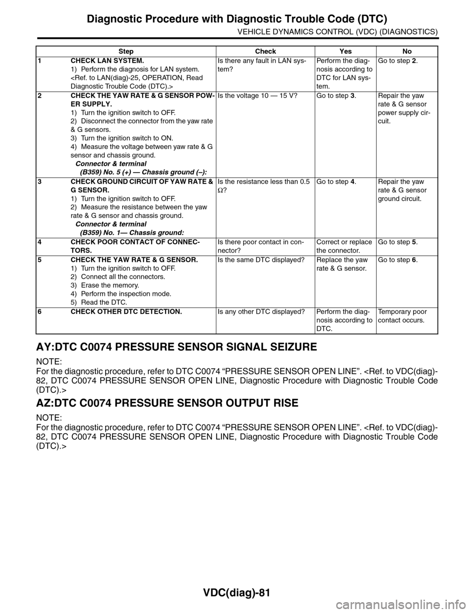
Step Check Yes No
1CHECK LAN SYSTEM.
1) Perform the diagnosis for LAN system.
Is there any fault in LAN sys-
tem?
Pe r for m t h e d ia g -
nosis according to
DTC for LAN sys-
tem.
Go to step 2.
2CHECK THE YAW RATE & G SENSOR POW-
ER SUPPLY.
1) Turn the ignition switch to OFF.
2) Disconnect the connector from the yaw rate
& G sensors.
3) Turn the ignition switch to ON.
4) Measure the voltage between yaw rate & G
sensor and chassis ground.
Connector & terminal
(B359) No. 5 (+) — Chassis ground (–):
Is the voltage 10 — 15 V? Go to step 3.Repair the yaw
rate & G sensor
power supply cir-
cuit.
3CHECK GROUND CIRCUIT OF YAW RATE &
G SENSOR.
1) Turn the ignition switch to OFF.
2) Measure the resistance between the yaw
rate & G sensor and chassis ground.
Connector & terminal
(B359) No. 1— Chassis ground:
Is the resistance less than 0.5
Ω?
Go to step 4.Repair the yaw
rate & G sensor
ground circuit.
4CHECK POOR CONTACT OF CONNEC-
TORS.
Is there poor contact in con-
nector?
Correct or replace
the connector.
Go to step 5.
5CHECK THE YAW RATE & G SENSOR.
1) Turn the ignition switch to OFF.
2) Connect all the connectors.
3) Erase the memory.
4) Perform the inspection mode.
5) Read the DTC.
Is the same DTC displayed? Replace the yaw
rate & G sensor.
Go to step 6.
6CHECK OTHER DTC DETECTION.Is any other DTC displayed? Perform the diag-
nosis according to
DTC.
Te m p o r a r y p o o r
contact occurs.
Page 1078 of 2453
VDC(diag)-86
Diagnostic Procedure with Diagnostic Trouble Code (DTC)
VEHICLE DYNAMICS CONTROL (VDC) (DIAGNOSTICS)
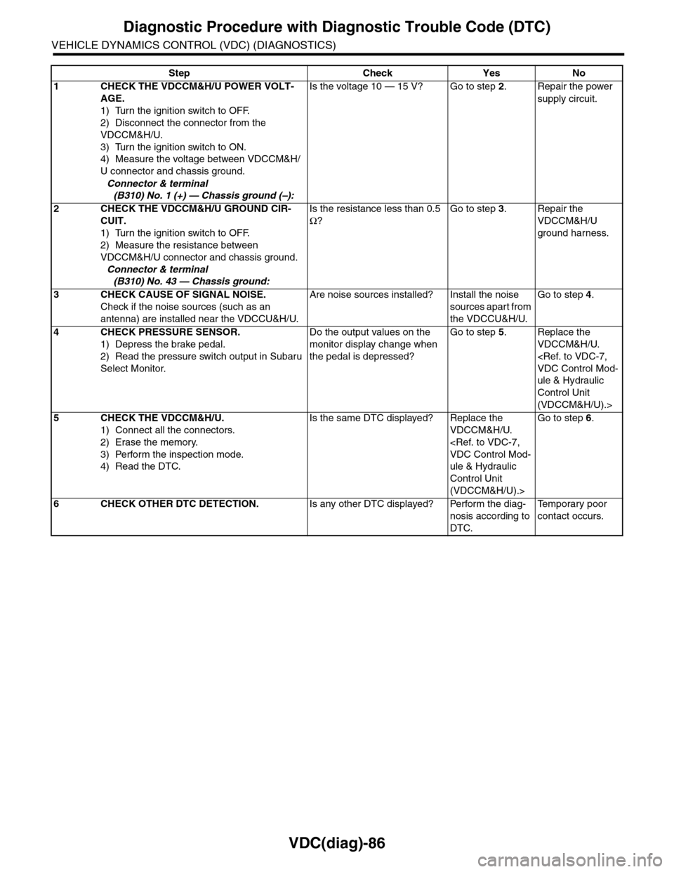
Step Check Yes No
1CHECK THE VDCCM&H/U POWER VOLT-
AGE.
1) Turn the ignition switch to OFF.
2) Disconnect the connector from the
VDCCM&H/U.
3) Turn the ignition switch to ON.
4) Measure the voltage between VDCCM&H/
U connector and chassis ground.
Connector & terminal
(B310) No. 1 (+) — Chassis ground (–):
Is the voltage 10 — 15 V? Go to step 2.Repair the power
supply circuit.
2CHECK THE VDCCM&H/U GROUND CIR-
CUIT.
1) Turn the ignition switch to OFF.
2) Measure the resistance between
VDCCM&H/U connector and chassis ground.
Connector & terminal
(B310) No. 43 — Chassis ground:
Is the resistance less than 0.5
Ω?
Go to step 3.Repair the
VDCCM&H/U
ground harness.
3CHECK CAUSE OF SIGNAL NOISE.
Check if the noise sources (such as an
antenna) are installed near the VDCCU&H/U.
Are noise sources installed? Install the noise
sources apart from
the VDCCU&H/U.
Go to step 4.
4CHECK PRESSURE SENSOR.
1) Depress the brake pedal.
2) Read the pressure switch output in Subaru
Select Monitor.
Do the output values on the
monitor display change when
the pedal is depressed?
Go to step 5.Replace the
VDCCM&H/U.
ule & Hydraulic
Control Unit
(VDCCM&H/U).>
5CHECK THE VDCCM&H/U.
1) Connect all the connectors.
2) Erase the memory.
3) Perform the inspection mode.
4) Read the DTC.
Is the same DTC displayed? Replace the
VDCCM&H/U.
ule & Hydraulic
Control Unit
(VDCCM&H/U).>
Go to step 6.
6CHECK OTHER DTC DETECTION.Is any other DTC displayed? Perform the diag-
nosis according to
DTC.
Te m p o r a r y p o o r
contact occurs.
Page 1128 of 2453
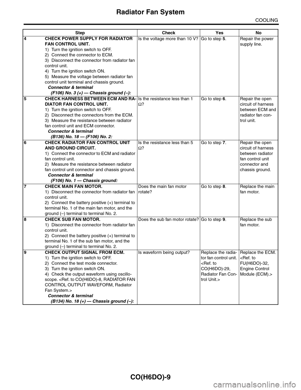
CO(H6DO)-9
Radiator Fan System
COOLING
4CHECK POWER SUPPLY FOR RADIATOR
FAN CONTROL UNIT.
1) Turn the ignition switch to OFF.
2) Connect the connector to ECM.
3) Disconnect the connector from radiator fan
control unit.
4) Turn the ignition switch ON.
5) Measure the voltage between radiator fan
control unit terminal and chassis ground.
Connector & terminal
(F106) No. 3 (+) — Chassis ground (–):
Is the voltage more than 10 V? Go to step 5.Repair the power
supply line.
5CHECK HARNESS BETWEEN ECM AND RA-
DIATOR FAN CONTROL UNIT.
1) Turn the ignition switch to OFF.
2) Disconnect the connectors from the ECM.
3) Measure the resistance between radiator
fan control unit and ECM connector.
Connector & terminal
(B136) No. 18 — (F106) No. 2:
Is the resistance less than 1
Ω?
Go to step 6.Repair the open
circuit of harness
between ECM and
radiator fan con-
trol unit.
6CHECK RADIATOR FAN CONTROL UNIT
AND GROUND CIRCUIT.
1) Connect the connector to ECM and radiator
fan control unit.
2) Measure the resistance between radiator
fan control unit connector and chassis ground.
Connector & terminal
(F106) No. 1 — Chassis ground:
Is the resistance less than 5
Ω?
Go to step 7.Repair the open
circuit of harness
between radiator
fan control unit
connector and
chassis ground.
7CHECK MAIN FAN MOTOR.
1) Disconnect the connector from radiator fan
control unit.
2) Connect the battery positive (+) terminal to
terminal No. 1 of the main fan motor, and the
ground (–) terminal to terminal No. 2.
Does the main fan motor
rotate?
Go to step 8.Replace the main
fan motor.
8CHECK SUB FAN MOTOR.
1) Disconnect the connector from radiator fan
control unit.
2) Connect the battery positive (+) terminal to
terminal No. 1 of the sub fan motor, and the
ground (–) terminal to terminal No. 2.
Does the sub fan motor rotate? Go to step 9.Replace the sub
fan motor.
9CHECK OUTPUT SIGNAL FROM ECM.
1) Turn the ignition switch to OFF.
2) Connect the test mode connector.
3) Turn the ignition switch ON.
4) Check the output waveform using oscillo-
scope.
Fa n S y st e m. >
Connector & terminal
(B134) No. 18 (+) — Chassis ground (–):
Is waveform being output? Replace the radia-
tor fan control unit.
Radiator Fan Con-
trol Unit.>
Replace the ECM.
Engine Control
Module (ECM).>
Step Check Yes No
Page 1167 of 2453
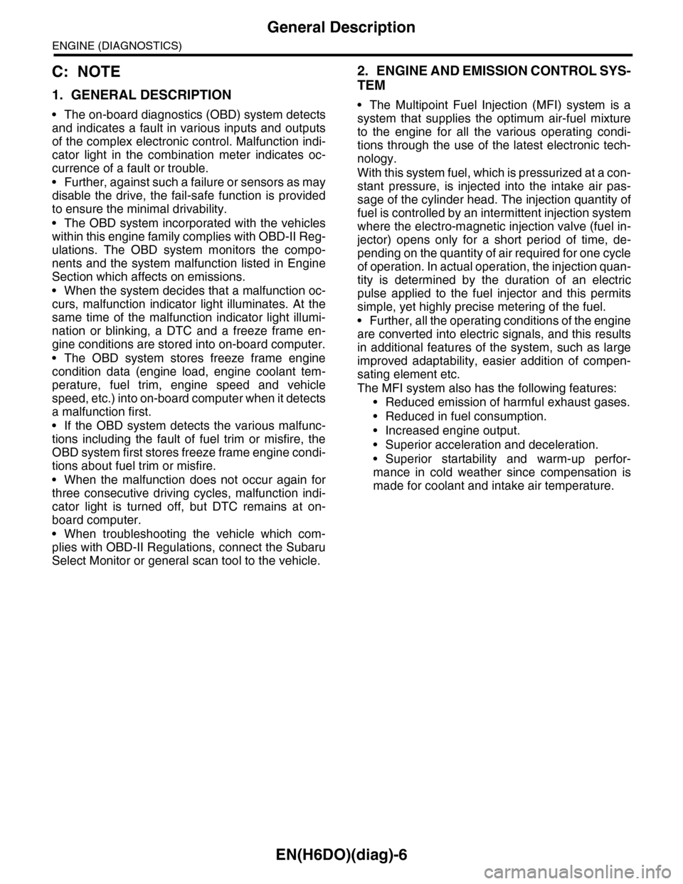
EN(H6DO)(diag)-6
General Description
ENGINE (DIAGNOSTICS)
C: NOTE
1. GENERAL DESCRIPTION
•The on-board diagnostics (OBD) system detects
and indicates a fault in various inputs and outputs
of the complex electronic control. Malfunction indi-
cator light in the combination meter indicates oc-
currence of a fault or trouble.
•Further, against such a failure or sensors as may
disable the drive, the fail-safe function is provided
to ensure the minimal drivability.
•The OBD system incorporated with the vehicles
within this engine family complies with OBD-II Reg-
ulations. The OBD system monitors the compo-
nents and the system malfunction listed in Engine
Section which affects on emissions.
•When the system decides that a malfunction oc-
curs, malfunction indicator light illuminates. At the
same time of the malfunction indicator light illumi-
nation or blinking, a DTC and a freeze frame en-
gine conditions are stored into on-board computer.
•The OBD system stores freeze frame engine
condition data (engine load, engine coolant tem-
perature, fuel trim, engine speed and vehicle
speed, etc.) into on-board computer when it detects
a malfunction first.
•If the OBD system detects the various malfunc-
tions including the fault of fuel trim or misfire, the
OBD system first stores freeze frame engine condi-
tions about fuel trim or misfire.
•When the malfunction does not occur again for
three consecutive driving cycles, malfunction indi-
cator light is turned off, but DTC remains at on-
board computer.
•When troubleshooting the vehicle which com-
plies with OBD-II Regulations, connect the Subaru
Select Monitor or general scan tool to the vehicle.
2. ENGINE AND EMISSION CONTROL SYS-
TEM
•The Multipoint Fuel Injection (MFI) system is a
system that supplies the optimum air-fuel mixture
to the engine for all the various operating condi-
tions through the use of the latest electronic tech-
nology.
With this system fuel, which is pressurized at a con-
stant pressure, is injected into the intake air pas-
sage of the cylinder head. The injection quantity of
fuel is controlled by an intermittent injection system
where the electro-magnetic injection valve (fuel in-
jector) opens only for a short period of time, de-
pending on the quantity of air required for one cycle
of operation. In actual operation, the injection quan-
tity is determined by the duration of an electric
pulse applied to the fuel injector and this permits
simple, yet highly precise metering of the fuel.
•Further, all the operating conditions of the engine
are converted into electric signals, and this results
in additional features of the system, such as large
improved adaptability, easier addition of compen-
sating element etc.
The MFI system also has the following features:
•Reduced emission of harmful exhaust gases.
•Reduced in fuel consumption.
•Increased engine output.
•Superior acceleration and deceleration.
•Superior startability and warm-up perfor-
mance in cold weather since compensation is
made for coolant and intake air temperature.
Page 1177 of 2453
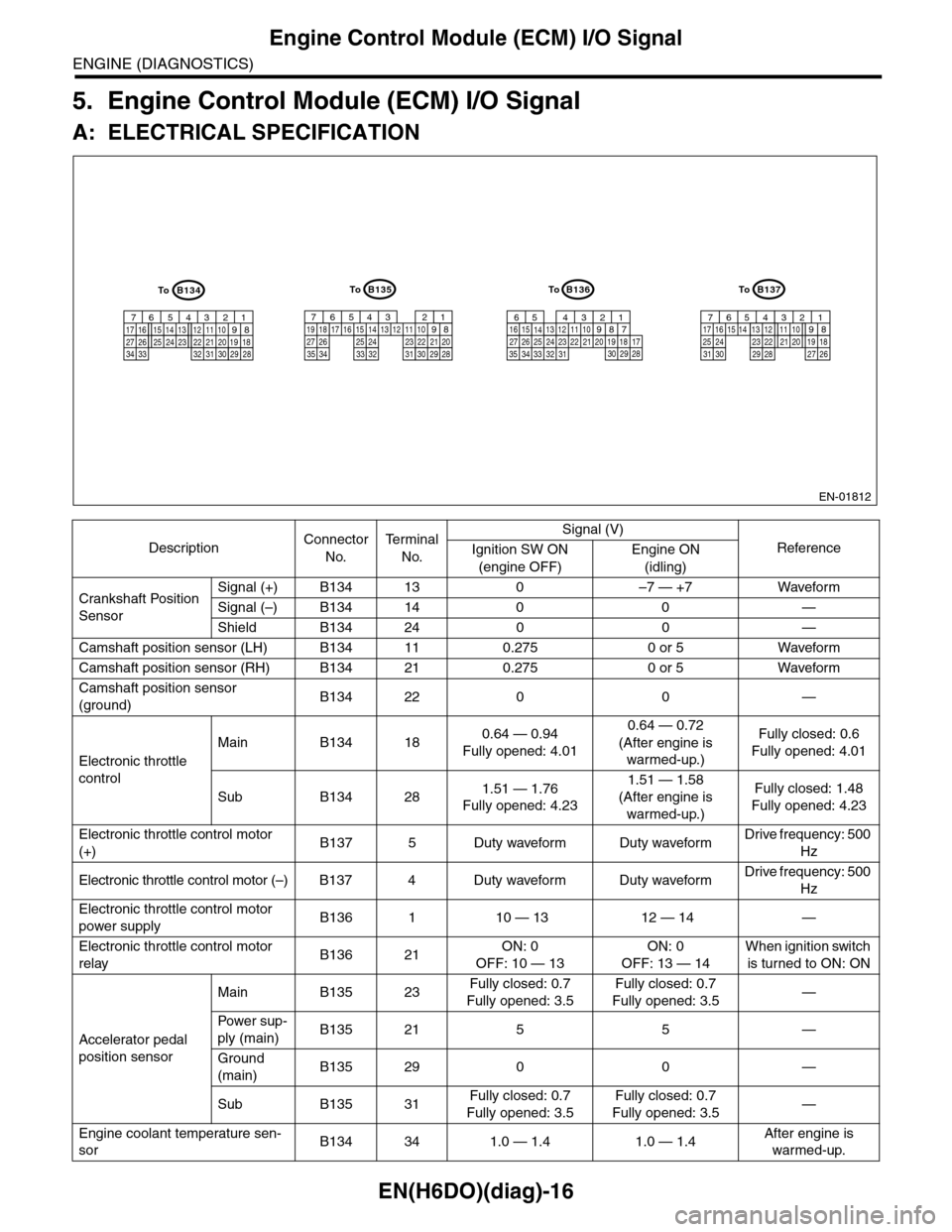
EN(H6DO)(diag)-16
Engine Control Module (ECM) I/O Signal
ENGINE (DIAGNOSTICS)
5. Engine Control Module (ECM) I/O Signal
A: ELECTRICAL SPECIFICATION
DescriptionConnector
No.
Te r m i n a l
No.
Signal (V)
ReferenceIgnition SW ON
(engine OFF)
Engine ON
(idling)
Crankshaft Position
Sensor
Signal (+) B134 13 0 –7 — +7 Waveform
Signal (–) B134 14 0 0 —
Shield B134 24 0 0 —
Camshaft position sensor (LH) B134 11 0.275 0 or 5 Waveform
Camshaft position sensor (RH) B134 21 0.275 0 or 5 Waveform
Camshaft position sensor
(ground)B134 22 0 0 —
Electronic throttle
control
Main B134 180.64 — 0.94
Fully opened: 4.01
0.64 — 0.72
(After engine is
warmed-up.)
Fully closed: 0.6
Fully opened: 4.01
Sub B134 281.51 — 1.76
Fully opened: 4.23
1.51 — 1.58
(After engine is
warmed-up.)
Fully closed: 1.48
Fully opened: 4.23
Electronic throttle control motor
(+)B137 5 Duty waveform Duty waveformDrive frequency: 500
Hz
Electronic throttle control motor (–) B137 4 Duty waveform Duty waveformDrive frequency: 500
Hz
Electronic throttle control motor
power supplyB136 1 10 — 13 12 — 14 —
Electronic throttle control motor
relayB136 21ON: 0
OFF: 10 — 13
ON: 0
OFF: 13 — 14
When ignition switch
is turned to ON: ON
Accelerator pedal
position sensor
Main B135 23Fully closed: 0.7
Fully opened: 3.5
Fully closed: 0.7
Fully opened: 3.5—
Powe r s up -
ply (main)B135 21 5 5 —
Ground
(main)B135 29 0 0 —
Sub B135 31Fully closed: 0.7
Fully opened: 3.5
Fully closed: 0.7
Fully opened: 3.5—
Engine coolant temperature sen-
sorB134 34 1.0 — 1.4 1.0 — 1.4After engine is
warmed-up.
EN-01812
B134
5678219431024 2223251112131415262728
1617181920213334 2932 3031
B136
5678219431024 2223251112131415262728
16171819202133342932303135
B135
5678219431024 2223251112131415262728
16171819202129303132333435
B137
5678219431022231112131415242526
1617181920212728293031
ToToToTo
Page 1197 of 2453
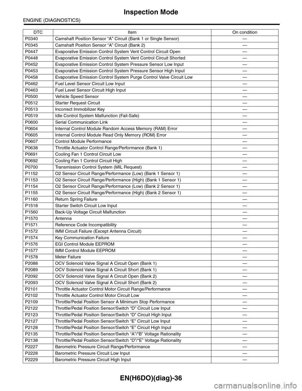
EN(H6DO)(diag)-36
Inspection Mode
ENGINE (DIAGNOSTICS)
P0340 Camshaft Position Sensor “A” Circuit (Bank 1 or Single Sensor) —
P0345 Camshaft Position Sensor “A” Circuit (Bank 2) —
P0447 Evaporative Emission Control System Vent Control Circuit Open —
P0448 Evaporative Emission Control System Vent Control Circuit Shorted —
P0452 Evaporative Emission Control System Pressure Sensor Low Input —
P0453 Evaporative Emission Control System Pressure Sensor High Input —
P0458 Evaporative Emission Control System Purge Control Valve Circuit Low —
P0462 Fuel Level Sensor Circuit Low Input —
P0463 Fuel Level Sensor Circuit High Input —
P0500 Vehicle Speed Sensor—
P0512 Starter Request Circuit—
P0513 Incorrect Immobilizer Key —
P0519 Idle Control System Malfunction (Fail-Safe) —
P0600 Serial Communication Link —
P0604 Internal Control Module Random Access Memory (RAM) Error —
P0605 Internal Control Module Read Only Memory (ROM) Error —
P0607 Control Module Performance —
P0638 Throttle Actuator Control Range/Performance (Bank 1) —
P0691 Cooling Fan 1 Control Circuit Low —
P0692 Cooling Fan 1 Control Circuit High —
P0700 Transmission Control System (MIL Request) —
P1152 O2 Sensor Circuit Range/Performance (Low) (Bank 1 Sensor 1) —
P1153 O2 Sensor Circuit Range/Performance (High) (Bank 1 Sensor 1) —
P1154 O2 Sensor Circuit Range/Performance (Low) (Bank 2 Sensor 1) —
P1155 O2 Sensor Circuit Range/Performance (High) (Bank 2 Sensor 1) —
P1160 Return Spring Failure—
P1518 Starter Switch Circuit Low Input —
P1560 Back-Up Voltage Circuit Malfunction —
P1570 Antenna—
P1571 Reference Code Incompatibility —
P1572 IMM Circuit Failure (Except Antenna Circuit) —
P1574 Key Communication Failure —
P1576 EGI Control Module EEPROM —
P1577 IMM Control Module EEPROM —
P1578 Meter Failure—
P2088 OCV Solenoid Valve Signal A Circuit Open (Bank 1) —
P2089 OCV Solenoid Valve Signal A Circuit Short (Bank 1) —
P2092 OCV Solenoid Valve Signal A Circuit Open (Bank 2) —
P2093 OCV Solenoid Valve Signal A Circuit Short (Bank 2) —
P2101 Throttle Actuator Control Motor Circuit Range/Performance —
P2102 Throttle Actuator Control Motor Circuit Low —
P2109 Throttle/Pedal Position Sensor A Minimum Stop Performance —
P2122 Throttle/Pedal Position Sensor/Switch “D” Circuit Low Input —
P2123 Throttle/Pedal Position Sensor/Switch “D” Circuit High Input —
P2127 Throttle/Pedal Position Sensor/Switch “E” Circuit Low Input —
P2128 Throttle/Pedal Position Sensor/Switch “E” Circuit High Input —
P2135 Throttle/Pedal Position Sensor/Switch “A”/“B” Voltage Rationality —
P2138 Throttle/Pedal Position Sensor/Switch “D”/“E” Voltage Rationality —
P2227 Barometric Pressure Circuit Range/Performance —
P2228 Barometric Pressure Circuit Low Input —
P2229 Barometric Pressure Circuit High Input —
DTC Item On condition