Page 260 of 2453
EI-18
Fuel Tank Protector
EXTERIOR/INTERIOR TRIM
3. Fuel Tank Protector
A: REMOVAL
1) Remove the bolts (A) and nuts (B), and then re-
move the fuel tank protector.
B: INSTALLATION
Install in the reverse order of removal.
Tightening torque:
Bolt
17.5 N·m (1.78 kgf-m, 12.9 ft-lb)
EI-01265(A)
(A)(A)
(A)
(A)
(A)
(B)(B)(B)(B)
Page 264 of 2453
EI-22
Front Bumper
EXTERIOR/INTERIOR TRIM
2. FRONT BUMPER BEAM ASSEMBLY
1) Remove the front bumper face.
2) Remove the energy absorber foam from bumper
beam.
3) Remove the bolts, and remove the bumper
beam assembly from vehicle body.
NOTE:
After all bolts are removed, raise the whole bumper
beam a little to remove it from vehicle body.
B: INSTALLATION
1. FRONT BUMPER FACE
1) Mount the bumper face securely in the gap be-
tween guide bracket (A) and fender (B).
2) Install in the reverse order of removal.
2. FRONT BUMPER BEAM ASSEMBLY
Install in the reverse order of removal.
Tightening torque:
Refer to “COMPONENT” of “General Descrip-
tion”.
NENT, General Description.>
EI-01271
EI-01272
(A)
(B)
Page 271 of 2453
EI-29
Rear Bumper
EXTERIOR/INTERIOR TRIM
B: INSTALLATION
Install in the reverse order of removal.
Tightening torque:
Refer to “COMPONENT” of “General Descrip-
tion”.
General Description.>
C: REPAIR
Refer to front bumper repair.
PAIR, Front Bumper.>
Page 273 of 2453
EI-31
Roof Spoiler
EXTERIOR/INTERIOR TRIM
9. Roof Spoiler
A: REMOVAL
1) Remove the rear gate upper trim.
REMOVAL, Rear Gate Trim.>
2) Disconnect the connector of high-mounted stop
light and the washer hose of rear washer.
3) Remove the nuts.
4) Remove the clips, and remove the roof spoiler.
B: INSTALLATION
Install in the reverse order of removal.
Tightening torque:
4.5 N·m (0.46 kgf-m, 3.32 ft-lb)
EI-01283
EI-01284
Page 276 of 2453

EI-34
Roof Molding
EXTERIOR/INTERIOR TRIM
11.Roof Molding
A: REMOVAL
1) Turn over the edge of the roof molding, and re-
move the inside clips with flat tip screwdriver by
sliding as arrow indicates.
Right side: slide towards the front of the vehicle.
Left side: slide towards the rear of the vehicle.
2) Pull the roof molding upward, and remove it from
vehicle body.
3) Remove the roof trim.
LATION, Roof Trim.>
4) Remove the nuts, and remove the roof carrier at-
tachment.
B: INSTALLATION
1) Install the roof carrier attachment.
Tightening torque:
7.5 N·m (0.77 kgf-m, 5.53 ft-lb)
2) Remove each clip from the roof molding, and in-
stall them to the vehicle side.
CAUTION:
Always replace clips damaged during removal
of the roof moulding with new clips.
3) Push the front edge of roof molding against the
front window, and install the positioning clip on the
front end to the rivet on the vehicle side.
EI-00509
EI-01380
(1) Windshield
(2) Positioning clips
(3) Roof molding
(4) Rivet
(5) Clip
EI-00659
EI-01381
(2)
(1)
(4)(5)
(3)
Page 284 of 2453

EI-42
Instrument Panel Assembly
EXTERIOR/INTERIOR TRIM
B: INSTALLATION
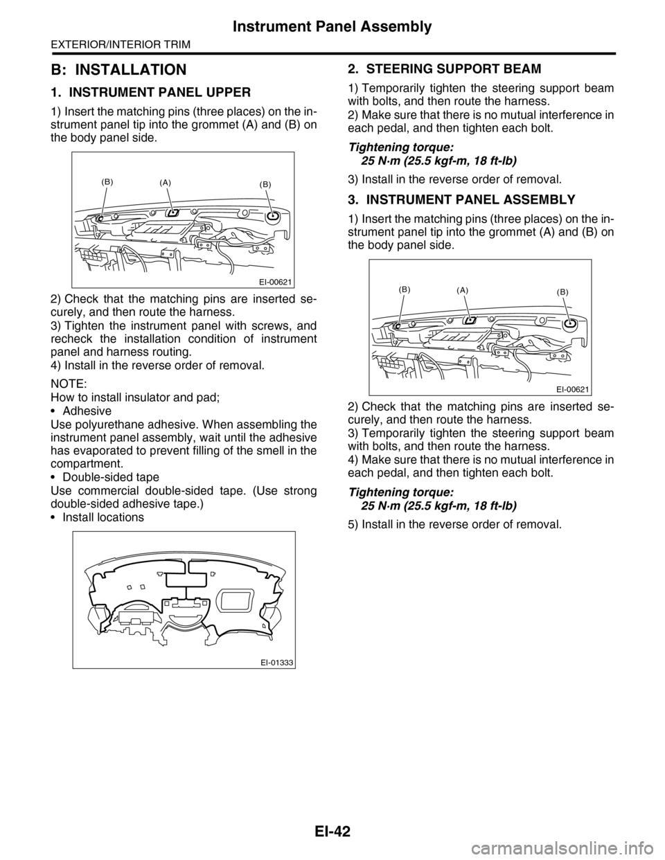
1. INSTRUMENT PANEL UPPER
1) Insert the matching pins (three places) on the in-
strument panel tip into the grommet (A) and (B) on
the body panel side.
2) Check that the matching pins are inserted se-
curely, and then route the harness.
3) Tighten the instrument panel with screws, and
recheck the installation condition of instrument
panel and harness routing.
4) Install in the reverse order of removal.
NOTE:
How to install insulator and pad;
•Adhesive
Use polyurethane adhesive. When assembling the
instrument panel assembly, wait until the adhesive
has evaporated to prevent filling of the smell in the
compartment.
•Double-sided tape
Use commercial double-sided tape. (Use strong
double-sided adhesive tape.)
•Install locations
2. STEERING SUPPORT BEAM
1) Temporarily tighten the steering support beam
with bolts, and then route the harness.
2) Make sure that there is no mutual interference in
each pedal, and then tighten each bolt.
Tightening torque:
25 N·m (25.5 kgf-m, 18 ft-lb)
3) Install in the reverse order of removal.
3. INSTRUMENT PANEL ASSEMBLY
1) Insert the matching pins (three places) on the in-
strument panel tip into the grommet (A) and (B) on
the body panel side.
2) Check that the matching pins are inserted se-
curely, and then route the harness.
3) Temporarily tighten the steering support beam
with bolts, and then route the harness.
4) Make sure that there is no mutual interference in
each pedal, and then tighten each bolt.
Tightening torque:
25 N·m (25.5 kgf-m, 18 ft-lb)
5) Install in the reverse order of removal.
EI-00621
(B)(B)(A)
EI-01333
EI-00621
(B)(B)(A)
Page 294 of 2453
EI-52
Rear Gate Garnish
EXTERIOR/INTERIOR TRIM
25.Rear Gate Garnish
A: REMOVAL
1) Remove the hexagon cap nut (A).
2) Remove the rear gate garnish.
B: INSTALLATION
Use new double-sided tapes, and install in the re-
verse order of removal.
NOTE:
Refer to the installing procedure of side garnish.
Tightening torque:
4.5 N·m (0.46 kgf-m, 3.32ft-lb)
(A) Hexagon cap nut
(B) Double-sided tape
EI-01355
(A)
EI-01356
(B)
(A)
Page 296 of 2453
EI-54
Trailer Hitch
EXTERIOR/INTERIOR TRIM
27.Trailer Hitch
A: REMOVAL
1) Remove the spare tire hoist.
REMOVAL, Spare Tire Hoist.>
2) Remove the bolt, and then detach the main
frame.
CAUTION:
The trailer hitch main frame is heavy. Be careful
when removing.
3) Remove the bolts, and then remove the center
frame.
4) Remove the side frame from the vehicle.
B: INSTALLATION
Install in the reverse order of removal.
Tightening torque:
Refer to “COMPONENT” of “General Descrip-
tion”.
NENT, General Description.>
EI-01383
EI-01384