Page 233 of 2453

EB-14
Front Hood
EXTERIOR BODY PANELS
4) Remove the front fender.
MOVAL, Front Fender.>
5) Remove the bolts of front hood hinge.
5. FRONT HOOD STRIKER
Refer to the front hood lock assembly of SL section.
Assembly.>
6. FRONT HOOD PANEL
1) Remove the front hood insulator.
2) Open the front hood to remove the window
washer hose.
3) Remove the front hood weather strip.
4) Remove the hood lock assembly.
sembly.>
5) Remove the window washer hose and nozzle.
zle.>
6) Remove the front hood damper.
7) Remove the bolt, and remove the front hood
panel from the front hood hinge.
B: INSTALLATION
Install in the reverse order of removal.
NOTE:
Be careful not to catch the window washer hose in.
Tightening torque:
Refer to “COMPONENT” of “General Descrip-
tion”.
NENT, General Description.>
C: ADJUSTMENT
1) Adjust the clearance between front hood panel
and front fender panel. Clearance must be equal at
both sides. For the dimension of clearance, refer to
“SPECIFICATION” in “General Description”.
to EB-2, SPECIFICATION, General Description.>
2) Use the hinge mounting bolts to align the front
hood longitudinal and lateral position.
3) Adjust the height at the front end of hood.
to SL-44, ADJUSTMENT, Front Hood Lock Assem-
bly.>
4) Rotate the hood buffer to adjust lateral height.
D: DISPOSAL
For the disposal procedures of front hood damper
stay, refer to the disposal procedures of rear gate
damper stay.
Gate.>
EB-00286
EB-00285
EB-00285
EB-00287
Page 234 of 2453
EB-15
Front Fender
EXTERIOR BODY PANELS
3. Front Fender
A: REMOVAL
1) Disconnect the ground cable from battery.
2) Remove the side sill guarnish.
REMOVAL, Side Garnish.>
3) Remove the front bumper.
MOVAL, Front Bumper.>
4) Remove the headlight assembly.
REMOVAL, Headlight Assembly.>
5) Remove the mud guard.
MOVAL, Mud Guard.>
6) Remove the cowl panel side.
7) Remove the bolt, and remove the front fender
panel.
B: INSTALLATION
1) Install in the reverse order of removal.
2) Install with attention to make uniform clearance
between front fender panel and front hood panel.
For the dimension of clearance, refer to “SPECIFI-
CATION” in “General Description”.
SPECIFICATION, General Description.>
Tightening torque:
7.4 N·m (0.75 kgf-m, 5.5 ft-lb)
EI-01280
(A)
EB-00279
Page 236 of 2453

EB-17
Front Door
EXTERIOR BODY PANELS
B: INSTALLATION
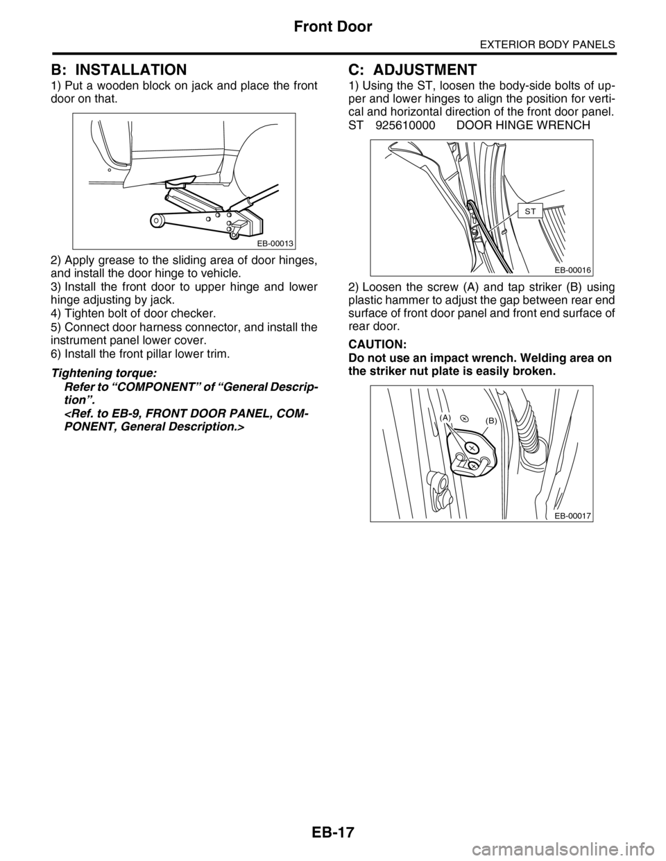
1) Put a wooden block on jack and place the front
door on that.
2) Apply grease to the sliding area of door hinges,
and install the door hinge to vehicle.
3) Install the front door to upper hinge and lower
hinge adjusting by jack.
4) Tighten bolt of door checker.
5) Connect door harness connector, and install the
instrument panel lower cover.
6) Install the front pillar lower trim.
Tightening torque:
Refer to “COMPONENT” of “General Descrip-
tion”.
PONENT, General Description.>
C: ADJUSTMENT
1) Using the ST, loosen the body-side bolts of up-
per and lower hinges to align the position for verti-
cal and horizontal direction of the front door panel.
ST 925610000 DOOR HINGE WRENCH
2) Loosen the screw (A) and tap striker (B) using
plastic hammer to adjust the gap between rear end
surface of front door panel and front end surface of
rear door.
CAUTION:
Do not use an impact wrench. Welding area on
the striker nut plate is easily broken.
EB-00013
EB-00016
ST
EB-00017
(B)(A)
Page 239 of 2453
EB-20
Rear Door
EXTERIOR BODY PANELS
B: INSTALLATION
1) Put a wooden block on jack and place the rear
door on that.
2) Apply grease to the moving part of door hinges.
3) Install the rear door to upper hinge and lower
hinge adjusting by jack.
4) Tighten bolt of door checker.
5) Connect the door harness connector.
Tightening torque:
Refer to “COMPONENT” of “General Descrip-
tion”.
PONENT, General Description.>
C: ADJUSTMENT
1) Open the rear door, loosen the door-side bolts of
upper and lower hinges to align the position for ver-
tical and horizontal direction of rear door panel.
2) Loosen the screw (A) and tap striker (B) using
plastic hammer to adjust the gap between rear end
surface of rear door panel and body surface.
CAUTION:
Do not use an impact wrench. Welding area on
the striker nut plate is easily broken.
EB-00013
EB-00015
EB-00017
(B)(A)
Page 242 of 2453

EB-23
Rear Gate
EXTERIOR BODY PANELS
14) Remove the rear gate hinge bolt, and remove
the rear gate panel.
15) Remove the rear gate hinge from the vehicle.
2. REAR GATE DAMPER STAY
CAUTION:
•Do not damage piston rods and oil seals.
•Never disassemble cylinders: They contain
gas.
1) Before removing the rear gate damper stay, pre-
vent the rear gate from closing using prop or the
like.
CAUTION:
If the prop comes off, operators may get injured
and vehicle may get damaged. Make sure to
support the rear gate with secure material to
prevent injury or damage.
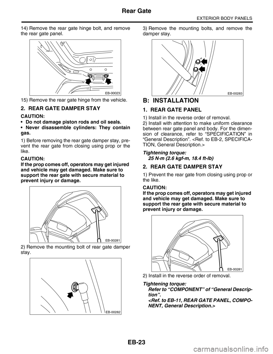
2) Remove the mounting bolt of rear gate damper
stay.
3) Remove the mounting bolts, and remove the
damper stay.
B: INSTALLATION
1. REAR GATE PANEL
1) Install in the reverse order of removal.
2) Install with attention to make uniform clearance
between rear gate panel and body. For the dimen-
sion of clearance, refer to “SPECIFICATION” in
“General Description”.
TION, General Description.>
Tightening torque:
25 N·m (2.6 kgf-m, 18.4 ft-lb)
2. REAR GATE DAMPER STAY
1) Prevent the rear gate from closing using prop or
the like.
CAUTION:
If the prop comes off, operators may get injured
and vehicle may get damaged. Make sure to
support the rear gate with secure material to
prevent injury or damage.
2) Install in the reverse order of removal.
Tightening torque:
Refer to “COMPONENT” of “General Descrip-
tion”.
NENT, General Description.>
EB-00023
EB-00281
EB-00282
EB-00283
EB-00281
Page 244 of 2453
EI-2
General Description
EXTERIOR/INTERIOR TRIM
1. General Description
A: COMPONENT
1. UNDER COVER
(1) Front lower coverTightening torque: N·m (kgf-m, ft-lb)
(2) Under cover T1: 7.5 (0.76, 5.4)
T2: 17.5 (1.78, 12.7)
EI-01248
T2T1
(1)
(2)
Page 245 of 2453
EI-3
General Description
EXTERIOR/INTERIOR TRIM
2. UNDER PROTECTOR
(1) Fuel tank protector RHTightening torque: N·m (kgf-m, ft-lb)
(2) Fuel tank protector LH T: 17.5 (1.78, 12.9)
EI-01249
T
T
T
(2)
(1)
Page 246 of 2453
EI-4
General Description
EXTERIOR/INTERIOR TRIM
3. FRONT BUMPER
(1) Bumper face (4) Bumper beam reinforcementTightening torque: N·m (kgf-m, ft-lb)
(2) Front upper cover (5) Fog light coverT: 33 (3.4, 24)
(3) Energy absorber foam
EI-01251
(2)
(1)
(5)
(3)
(4)
T