2009 SUBARU TRIBECA Harness
[x] Cancel search: HarnessPage 1081 of 2453
VDC(diag)-89
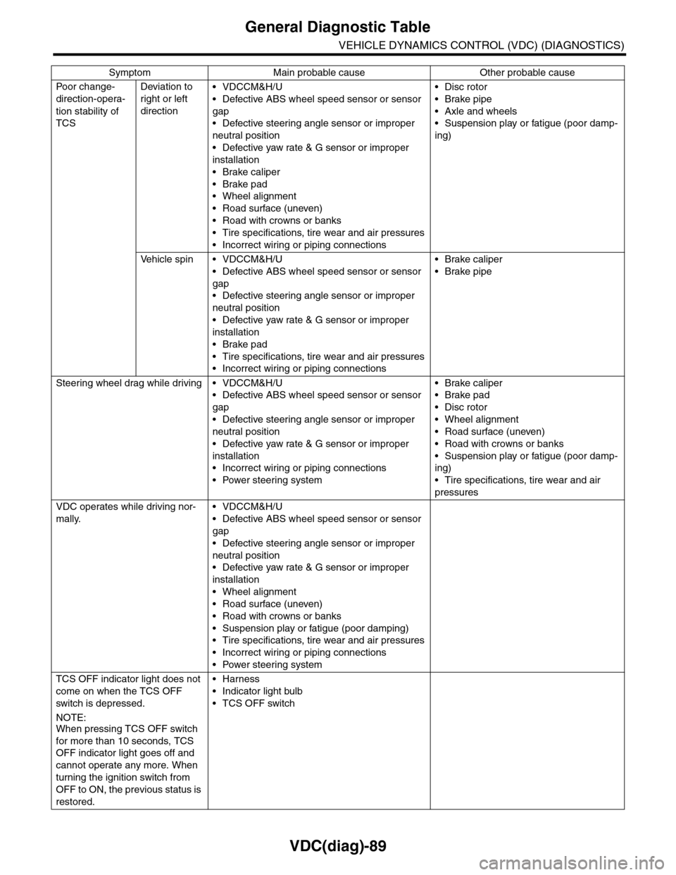
General Diagnostic Table
VEHICLE DYNAMICS CONTROL (VDC) (DIAGNOSTICS)
Po or ch a ng e -
direction-opera-
tion stability of
TCS
Deviation to
right or left
direction
•VDCCM&H/U
•Defective ABS wheel speed sensor or sensor
gap
•Defective steering angle sensor or improper
neutral position
•Defective yaw rate & G sensor or improper
installation
•Brake caliper
•Brake pad
•Wheel alignment
•Road surface (uneven)
•Road with crowns or banks
•Tire specifications, tire wear and air pressures
•Incorrect wiring or piping connections
•Disc rotor
•Brake pipe
•Axle and wheels
•Suspension play or fatigue (poor damp-
ing)
Ve h i c l e s p i n • V D C C M & H / U
•Defective ABS wheel speed sensor or sensor
gap
•Defective steering angle sensor or improper
neutral position
•Defective yaw rate & G sensor or improper
installation
•Brake pad
•Tire specifications, tire wear and air pressures
•Incorrect wiring or piping connections
•Brake caliper
•Brake pipe
Steering wheel drag while driving • VDCCM&H/U
•Defective ABS wheel speed sensor or sensor
gap
•Defective steering angle sensor or improper
neutral position
•Defective yaw rate & G sensor or improper
installation
•Incorrect wiring or piping connections
•Power steering system
•Brake caliper
•Brake pad
•Disc rotor
•Wheel alignment
•Road surface (uneven)
•Road with crowns or banks
•Suspension play or fatigue (poor damp-
ing)
•Tire specifications, tire wear and air
pressures
VDC operates while driving nor-
mally.
•VDCCM&H/U
•Defective ABS wheel speed sensor or sensor
gap
•Defective steering angle sensor or improper
neutral position
•Defective yaw rate & G sensor or improper
installation
•Wheel alignment
•Road surface (uneven)
•Road with crowns or banks
•Suspension play or fatigue (poor damping)
•Tire specifications, tire wear and air pressures
•Incorrect wiring or piping connections
•Power steering system
TCS OFF indicator light does not
come on when the TCS OFF
switch is depressed.
NOTE:When pressing TCS OFF switch
for more than 10 seconds, TCS
OFF indicator light goes off and
cannot operate any more. When
turning the ignition switch from
OFF to ON, the previous status is
restored.
•Harness
•Indicator light bulb
•TCS OFF switch
Symptom Main probable cause Other probable cause
Page 1083 of 2453
VDC-2
General Description
VEHICLE DYNAMICS CONTROL (VDC)
1. General Description
A: SPECIFICATION
B: COMPONENT
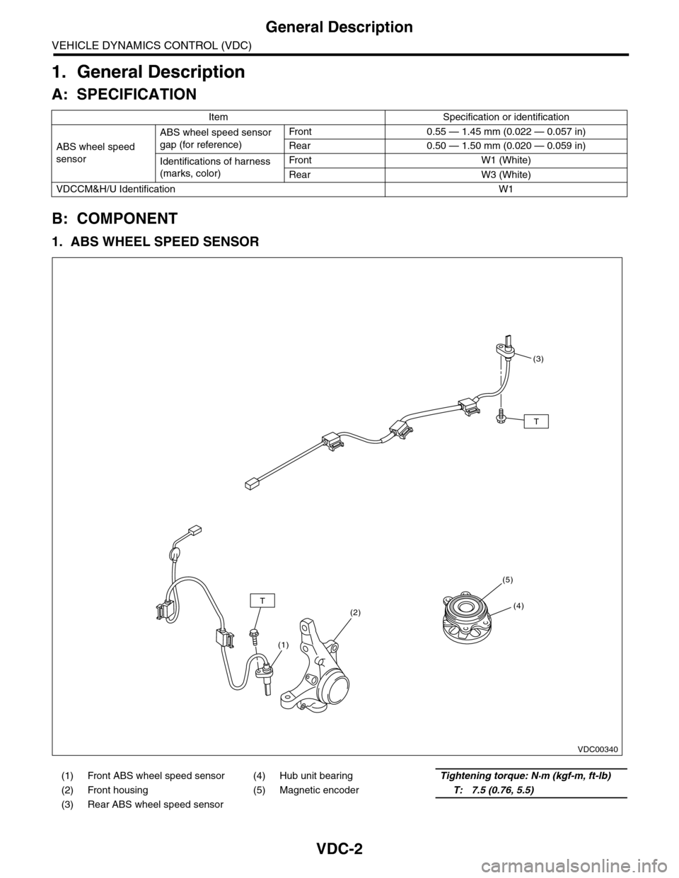
1. ABS WHEEL SPEED SENSOR
Item Specification or identification
ABS wheel speed
sensor
ABS wheel speed sensor
gap (for reference)
Fr o nt 0 . 55 — 1. 4 5 m m ( 0. 0 2 2 — 0. 0 57 i n)
Rear 0.50 — 1.50 mm (0.020 — 0.059 in)
Identifications of harness
(marks, color)
Fr o nt W1 ( Wh i te )
Rear W3 (White)
VDCCM&H/U IdentificationW1
(1) Front ABS wheel speed sensor (4) Hub unit bearingTightening torque: N·m (kgf-m, ft-lb)
(2) Front housing (5) Magnetic encoderT: 7.5 (0.76, 5.5)
(3) Rear ABS wheel speed sensor
VDC00340
T
T
(3)
(4)
(5)
(2)
(1)
Page 1088 of 2453
VDC-7
VDC Control Module & Hydraulic Control Unit (VDCCM&H/U)
VEHICLE DYNAMICS CONTROL (VDC)
2. VDC Control Module & Hy-
draulic Control Unit (VDC-
CM&H/U)
A: REMOVAL
1) Disconnect the ground cable from the battery.
2) Use compressed air to remove moisture and
dust around the VDCCM&H/U.
NOTE:
If the terminals become dirty, it may cause improp-
er contact.
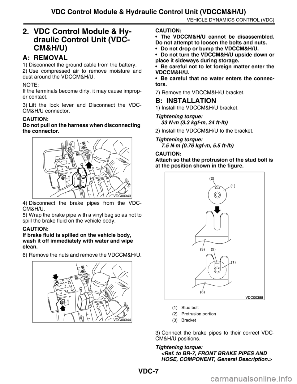
3) Lift the lock lever and Disconnect the VDC-
CM&H/U connector.
CAUTION:
Do not pull on the harness when disconnecting
the connector.
4) Disconnect the brake pipes from the VDC-
CM&H/U.
5) Wrap the brake pipe with a vinyl bag so as not to
spill the brake fluid on the vehicle body.
CAUTION:
If brake fluid is spilled on the vehicle body,
wash it off immediately with water and wipe
clean.
6) Remove the nuts and remove the VDCCM&H/U.
CAUTION:
•The VDCCM&H/U cannot be disassembled.
Do not attempt to loosen the bolts and nuts.
•Do not drop or bump the VDCCM&H/U.
•Do not turn the VDCCM&H/U upside down or
place it sideways during storage.
•Be careful not to let foreign matter enter the
VDCCM&H/U.
•Be careful that no water enters the connec-
tors.
7) Remove the VDCCM&H/U bracket.
B: INSTALLATION
1) Install the VDCCM&H/U bracket.
Tightening torque:
33 N·m (3.3 kgf-m, 24 ft-lb)
2) Install the VDCCM&H/U to the bracket.
Tightening torque:
7.5 N·m (0.76 kgf-m, 5.5 ft-lb)
CAUTION:
Attach so that the protrusion of the stud bolt is
at the position shown in the figure.
3) Connect the brake pipes to their correct VDC-
CM&H/U positions.
Tightening torque:
VDC00343
VDC00344
(1) Stud bolt
(2) Protrusion por tion
(3) Bracket
Page 1100 of 2453
VDC-19
Steering Angle Sensor
VEHICLE DYNAMICS CONTROL (VDC)
6. Steering Angle Sensor
A: REPLACEMENT
CAUTION:
•Do not perform the removal except when the
replacement.
•When replacing more than three times, re-
place the combination switch as assembly to
protect the threads.
1) Set the steering wheel in a straight-ahead posi-
tion.
2) Disconnect the ground cable from the battery.
3) Remove the airbag module.
WARNING:
Always refer to “Airbag System” when perform-
ing the airbag module repair service.
4) Remove the steering wheel.
5) Remove the screws and remove the steering
column lower cover.
6) Remove the two screws securing the steering
column upper cover.
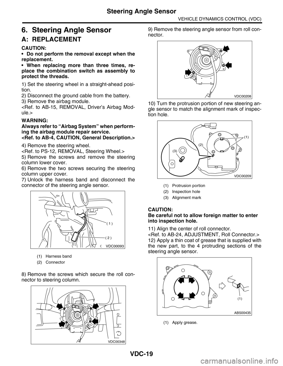
7) Unlock the harness band and disconnect the
connector of the steering angle sensor.
8) Remove the screws which secure the roll con-
nector to steering column.
9) Remove the steering angle sensor from roll con-
nector.
10) Turn the protrusion portion of new steering an-
gle sensor to match the alignment mark of inspec-
tion hole.
CAUTION:
Be careful not to allow foreign matter to enter
into inspection hole.
11) Align the center of roll connector.
12) Apply a thin coat of grease that is supplied with
the new part, to the 4 protruding sections of the
steering angle sensor.
(1) Harness band
(2) Connector
VDC00093
( 1 )
( 2 )
VDC00348
(1) Protrusion portion
(2) Inspection hole
(3) Alignment mark
(1) Apply grease.
VDC00208
VDC00209
(1)
(2)
(3)
ABS00435
(1)
Page 1102 of 2453
VDC-21
Front ABS Wheel Speed Sensor
VEHICLE DYNAMICS CONTROL (VDC)
7. Front ABS Wheel Speed Sen-
sor
A: REMOVAL
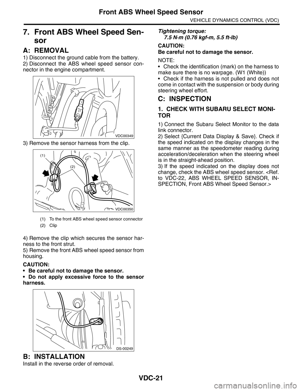
1) Disconnect the ground cable from the battery.
2) Disconnect the ABS wheel speed sensor con-
nector in the engine compartment.
3) Remove the sensor harness from the clip.
4) Remove the clip which secures the sensor har-
ness to the front strut.
5) Remove the front ABS wheel speed sensor from
housing.
CAUTION:
•Be careful not to damage the sensor.
•Do not apply excessive force to the sensor
harness.
B: INSTALLATION
Install in the reverse order of removal.
Tightening torque:
7.5 N·m (0.76 kgf-m, 5.5 ft-lb)
CAUTION:
Be careful not to damage the sensor.
NOTE:
•Check the identification (mark) on the harness to
make sure there is no warpage. (W1 (White))
•Check if the harness is not pulled and does not
come in contact with the suspension or body during
steering wheel effort.
C: INSPECTION
1. CHECK WITH SUBARU SELECT MONI-
TOR
1) Connect the Subaru Select Monitor to the data
link connector.
2) Select {Current Data Display & Save}. Check if
the speed indicated on the display changes in the
same manner as the speedometer reading during
acceleration/deceleration when the steering wheel
is in the straight-ahead position.
3) If the speed indicated on the display does not
change, check the ABS wheel speed sensor.
SPECTION, Front ABS Wheel Speed Sensor.>
(1) To the front ABS wheel speed sensor connector
(2) Clip
VDC00349
VDC00350
(1)
(2)
DS-00249
Page 1104 of 2453
VDC-23
Rear ABS Wheel Speed Sensor
VEHICLE DYNAMICS CONTROL (VDC)
8. Rear ABS Wheel Speed Sen-
sor
A: REMOVAL
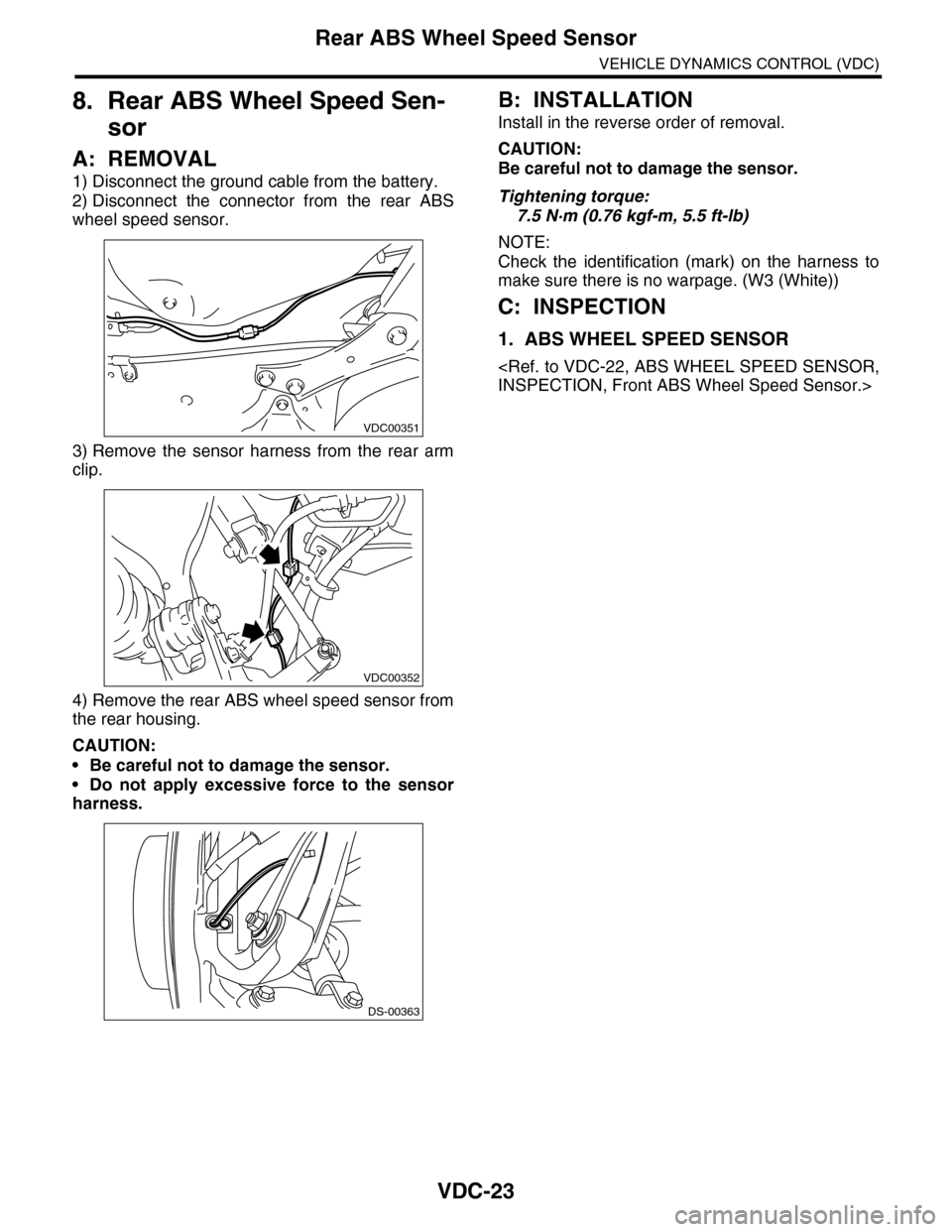
1) Disconnect the ground cable from the battery.
2) Disconnect the connector from the rear ABS
wheel speed sensor.
3) Remove the sensor harness from the rear arm
clip.
4) Remove the rear ABS wheel speed sensor from
the rear housing.
CAUTION:
•Be careful not to damage the sensor.
•Do not apply excessive force to the sensor
harness.
B: INSTALLATION
Install in the reverse order of removal.
CAUTION:
Be careful not to damage the sensor.
Tightening torque:
7.5 N·m (0.76 kgf-m, 5.5 ft-lb)
NOTE:
Check the identification (mark) on the harness to
make sure there is no warpage. (W3 (White))
C: INSPECTION
1. ABS WHEEL SPEED SENSOR
VDC00351
VDC00352
DS-00363
Page 1128 of 2453
CO(H6DO)-9
Radiator Fan System
COOLING
4CHECK POWER SUPPLY FOR RADIATOR
FAN CONTROL UNIT.
1) Turn the ignition switch to OFF.
2) Connect the connector to ECM.
3) Disconnect the connector from radiator fan
control unit.
4) Turn the ignition switch ON.
5) Measure the voltage between radiator fan
control unit terminal and chassis ground.
Connector & terminal
(F106) No. 3 (+) — Chassis ground (–):
Is the voltage more than 10 V? Go to step 5.Repair the power
supply line.
5CHECK HARNESS BETWEEN ECM AND RA-
DIATOR FAN CONTROL UNIT.
1) Turn the ignition switch to OFF.
2) Disconnect the connectors from the ECM.
3) Measure the resistance between radiator
fan control unit and ECM connector.
Connector & terminal
(B136) No. 18 — (F106) No. 2:
Is the resistance less than 1
Ω?
Go to step 6.Repair the open
circuit of harness
between ECM and
radiator fan con-
trol unit.
6CHECK RADIATOR FAN CONTROL UNIT
AND GROUND CIRCUIT.
1) Connect the connector to ECM and radiator
fan control unit.
2) Measure the resistance between radiator
fan control unit connector and chassis ground.
Connector & terminal
(F106) No. 1 — Chassis ground:
Is the resistance less than 5
Ω?
Go to step 7.Repair the open
circuit of harness
between radiator
fan control unit
connector and
chassis ground.
7CHECK MAIN FAN MOTOR.
1) Disconnect the connector from radiator fan
control unit.
2) Connect the battery positive (+) terminal to
terminal No. 1 of the main fan motor, and the
ground (–) terminal to terminal No. 2.
Does the main fan motor
rotate?
Go to step 8.Replace the main
fan motor.
8CHECK SUB FAN MOTOR.
1) Disconnect the connector from radiator fan
control unit.
2) Connect the battery positive (+) terminal to
terminal No. 1 of the sub fan motor, and the
ground (–) terminal to terminal No. 2.
Does the sub fan motor rotate? Go to step 9.Replace the sub
fan motor.
9CHECK OUTPUT SIGNAL FROM ECM.
1) Turn the ignition switch to OFF.
2) Connect the test mode connector.
3) Turn the ignition switch ON.
4) Check the output waveform using oscillo-
scope.
Fa n S y st e m. >
Connector & terminal
(B134) No. 18 (+) — Chassis ground (–):
Is waveform being output? Replace the radia-
tor fan control unit.
Radiator Fan Con-
trol Unit.>
Replace the ECM.
Engine Control
Module (ECM).>
Step Check Yes No
Page 1134 of 2453
CO(H6DO)-15
Radiator
COOLING
6. Radiator
A: REMOVAL
WARNING:
The radiator is pressurized. Wait until engine
cools down before working on the radiator.
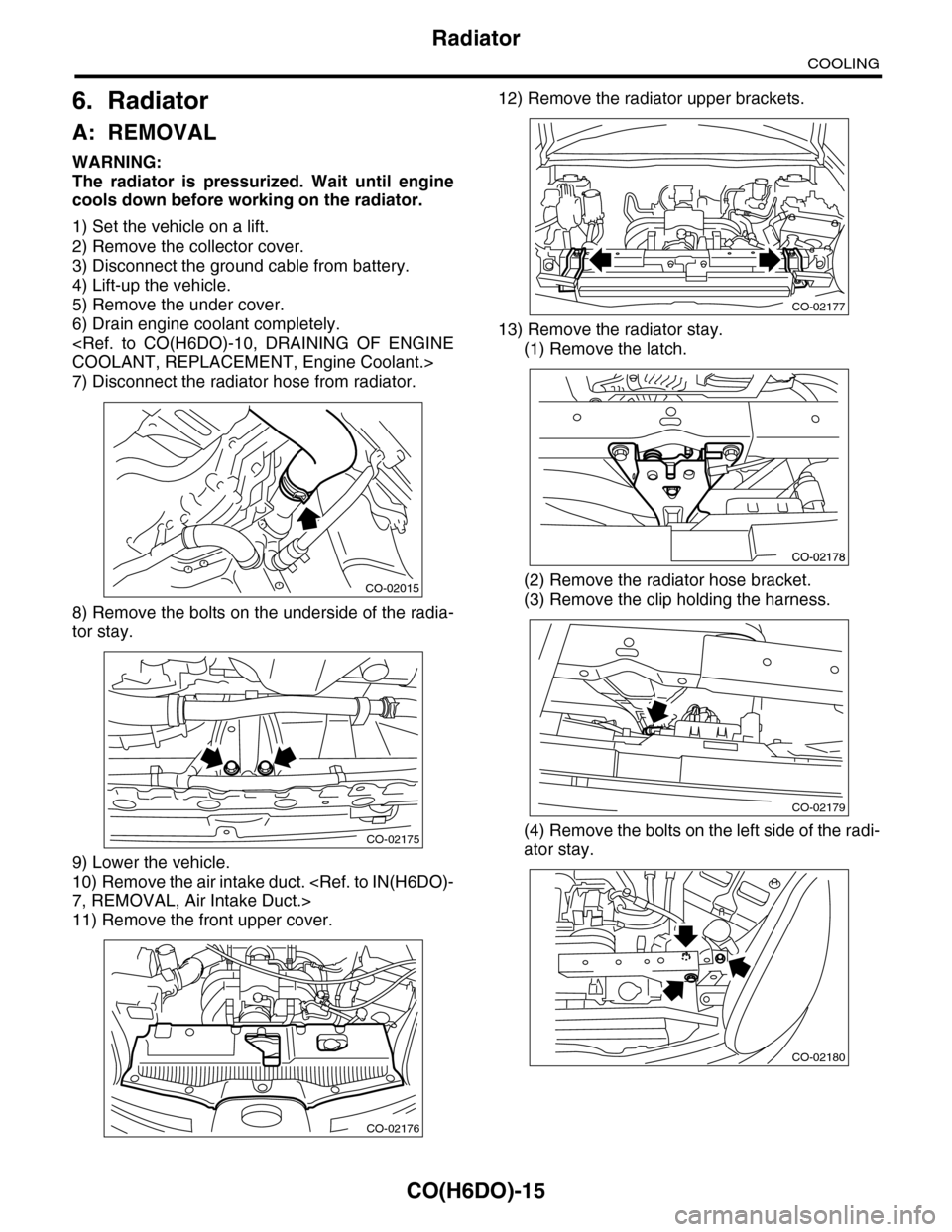
1) Set the vehicle on a lift.
2) Remove the collector cover.
3) Disconnect the ground cable from battery.
4) Lift-up the vehicle.
5) Remove the under cover.
6) Drain engine coolant completely.
7) Disconnect the radiator hose from radiator.
8) Remove the bolts on the underside of the radia-
tor stay.
9) Lower the vehicle.
10) Remove the air intake duct.
11) Remove the front upper cover.
12) Remove the radiator upper brackets.
13) Remove the radiator stay.
(1) Remove the latch.
(2) Remove the radiator hose bracket.
(3) Remove the clip holding the harness.
(4) Remove the bolts on the left side of the radi-
ator stay.
CO-02015
CO-02175
CO-02176
CO-02177
CO-02179
CO-02180