2009 SUBARU TRIBECA Harness
[x] Cancel search: HarnessPage 1221 of 2453
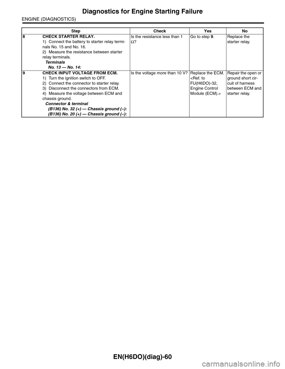
EN(H6DO)(diag)-60
Diagnostics for Engine Starting Failure
ENGINE (DIAGNOSTICS)
8CHECK STARTER RELAY.
1) Connect the battery to starter relay termi-
nals No. 15 and No. 16.
2) Measure the resistance between starter
relay terminals.
Te r m i n a l s
No. 13 — No. 14:
Is the resistance less than 1
Ω?
Go to step 9.Replace the
starter relay.
9CHECK INPUT VOLTAGE FROM ECM.
1) Turn the ignition switch to OFF.
2) Connect the connector to starter relay.
3) Disconnect the connectors from ECM.
4) Measure the voltage between ECM and
chassis ground.
Connector & terminal
(B136) No. 32 (+) — Chassis ground (–):
(B136) No. 20 (+) — Chassis ground (–):
Is the voltage more than 10 V? Replace the ECM.
Engine Control
Module (ECM).>
Repair the open or
ground short cir-
cuit of harness
between ECM and
starter relay.
Step Check Yes No
Page 1223 of 2453
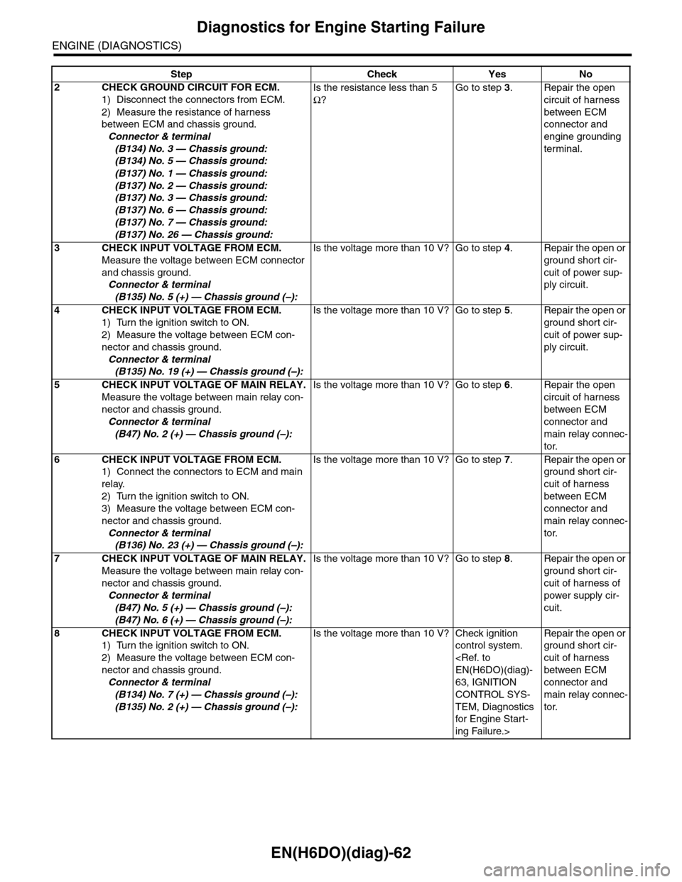
EN(H6DO)(diag)-62
Diagnostics for Engine Starting Failure
ENGINE (DIAGNOSTICS)
2CHECK GROUND CIRCUIT FOR ECM.
1) Disconnect the connectors from ECM.
2) Measure the resistance of harness
between ECM and chassis ground.
Connector & terminal
(B134) No. 3 — Chassis ground:
(B134) No. 5 — Chassis ground:
(B137) No. 1 — Chassis ground:
(B137) No. 2 — Chassis ground:
(B137) No. 3 — Chassis ground:
(B137) No. 6 — Chassis ground:
(B137) No. 7 — Chassis ground:
(B137) No. 26 — Chassis ground:
Is the resistance less than 5
Ω?
Go to step 3.Repair the open
circuit of harness
between ECM
connector and
engine grounding
terminal.
3CHECK INPUT VOLTAGE FROM ECM.
Measure the voltage between ECM connector
and chassis ground.
Connector & terminal
(B135) No. 5 (+) — Chassis ground (–):
Is the voltage more than 10 V? Go to step 4.Repair the open or
ground short cir-
cuit of power sup-
ply circuit.
4CHECK INPUT VOLTAGE FROM ECM.
1) Turn the ignition switch to ON.
2) Measure the voltage between ECM con-
nector and chassis ground.
Connector & terminal
(B135) No. 19 (+) — Chassis ground (–):
Is the voltage more than 10 V? Go to step 5.Repair the open or
ground short cir-
cuit of power sup-
ply circuit.
5CHECK INPUT VOLTAGE OF MAIN RELAY.
Measure the voltage between main relay con-
nector and chassis ground.
Connector & terminal
(B47) No. 2 (+) — Chassis ground (–):
Is the voltage more than 10 V? Go to step 6.Repair the open
circuit of harness
between ECM
connector and
main relay connec-
tor.
6CHECK INPUT VOLTAGE FROM ECM.
1) Connect the connectors to ECM and main
relay.
2) Turn the ignition switch to ON.
3) Measure the voltage between ECM con-
nector and chassis ground.
Connector & terminal
(B136) No. 23 (+) — Chassis ground (–):
Is the voltage more than 10 V? Go to step 7.Repair the open or
ground short cir-
cuit of harness
between ECM
connector and
main relay connec-
tor.
7CHECK INPUT VOLTAGE OF MAIN RELAY.
Measure the voltage between main relay con-
nector and chassis ground.
Connector & terminal
(B47) No. 5 (+) — Chassis ground (–):
(B47) No. 6 (+) — Chassis ground (–):
Is the voltage more than 10 V? Go to step 8.Repair the open or
ground short cir-
cuit of harness of
power supply cir-
cuit.
8CHECK INPUT VOLTAGE FROM ECM.
1) Turn the ignition switch to ON.
2) Measure the voltage between ECM con-
nector and chassis ground.
Connector & terminal
(B134) No. 7 (+) — Chassis ground (–):
(B135) No. 2 (+) — Chassis ground (–):
Is the voltage more than 10 V? Check ignition
control system.
63, IGNITION
CONTROL SYS-
TEM, Diagnostics
for Engine Star t-
ing Failure.>
Repair the open or
ground short cir-
cuit of harness
between ECM
connector and
main relay connec-
tor.
Step Check Yes No
Page 1225 of 2453
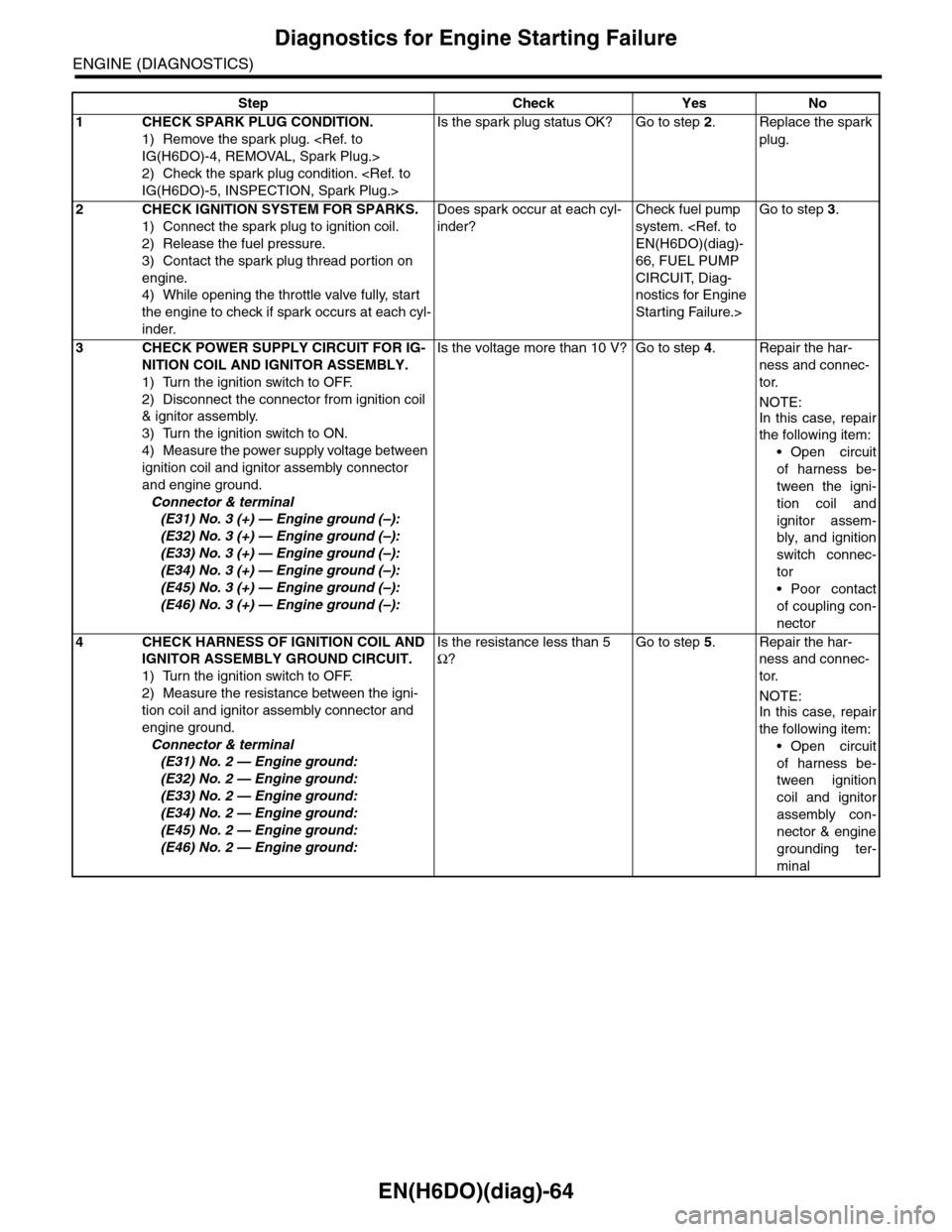
EN(H6DO)(diag)-64
Diagnostics for Engine Starting Failure
ENGINE (DIAGNOSTICS)
Step Check Yes No
1CHECK SPARK PLUG CONDITION.
1) Remove the spark plug.
2) Check the spark plug condition.
Is the spark plug status OK? Go to step 2.Replace the spark
plug.
2CHECK IGNITION SYSTEM FOR SPARKS.
1) Connect the spark plug to ignition coil.
2) Release the fuel pressure.
3) Contact the spark plug thread portion on
engine.
4) While opening the throttle valve fully, start
the engine to check if spark occurs at each cyl-
inder.
Does spark occur at each cyl-
inder?
Check fuel pump
system.
66, FUEL PUMP
CIRCUIT, Diag-
nostics for Engine
Starting Failure.>
Go to step 3.
3CHECK POWER SUPPLY CIRCUIT FOR IG-
NITION COIL AND IGNITOR ASSEMBLY.
1) Turn the ignition switch to OFF.
2) Disconnect the connector from ignition coil
& ignitor assembly.
3) Turn the ignition switch to ON.
4) Measure the power supply voltage between
ignition coil and ignitor assembly connector
and engine ground.
Connector & terminal
(E31) No. 3 (+) — Engine ground (–):
(E32) No. 3 (+) — Engine ground (–):
(E33) No. 3 (+) — Engine ground (–):
(E34) No. 3 (+) — Engine ground (–):
(E45) No. 3 (+) — Engine ground (–):
(E46) No. 3 (+) — Engine ground (–):
Is the voltage more than 10 V? Go to step 4.Repair the har-
ness and connec-
tor.
NOTE:
In this case, repair
the following item:
•Open circuit
of harness be-
tween the igni-
tion coil and
ignitor assem-
bly, and ignition
switch connec-
tor
•Poor contact
of coupling con-
nector
4CHECK HARNESS OF IGNITION COIL AND
IGNITOR ASSEMBLY GROUND CIRCUIT.
1) Turn the ignition switch to OFF.
2) Measure the resistance between the igni-
tion coil and ignitor assembly connector and
engine ground.
Connector & terminal
(E31) No. 2 — Engine ground:
(E32) No. 2 — Engine ground:
(E33) No. 2 — Engine ground:
(E34) No. 2 — Engine ground:
(E45) No. 2 — Engine ground:
(E46) No. 2 — Engine ground:
Is the resistance less than 5
Ω?
Go to step 5.Repair the har-
ness and connec-
tor.
NOTE:
In this case, repair
the following item:
•Open circuit
of harness be-
tween ignition
coil and ignitor
assembly con-
nector & engine
grounding ter-
minal
Page 1226 of 2453
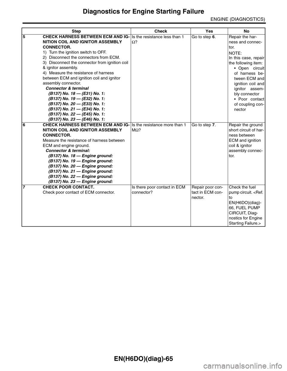
EN(H6DO)(diag)-65
Diagnostics for Engine Starting Failure
ENGINE (DIAGNOSTICS)
5CHECK HARNESS BETWEEN ECM AND IG-
NITION COIL AND IGNITOR ASSEMBLY
CONNECTOR.
1) Turn the ignition switch to OFF.
2) Disconnect the connectors from ECM.
3) Disconnect the connector from ignition coil
& ignitor assembly.
4) Measure the resistance of harness
between ECM and ignition coil and ignitor
assembly connector.
Connector & terminal
(B137) No. 18 — (E31) No. 1:
(B137) No. 19 — (E32) No. 1:
(B137) No. 20 — (E33) No. 1:
(B137) No. 21 — (E34) No. 1:
(B137) No. 22 — (E45) No. 1:
(B137) No. 23 — (E46) No. 1:
Is the resistance less than 1
Ω?
Go to step 6.Repair the har-
ness and connec-
tor.
NOTE:In this case, repair
the following item:
•Open circuit
of harness be-
tween ECM and
ignition coil and
ignitor assem-
bly connector
•Poor contact
of coupling con-
nector
6CHECK HARNESS BETWEEN ECM AND IG-
NITION COIL AND IGNITOR ASSEMBLY
CONNECTOR.
Measure the resistance of harness between
ECM and engine ground.
Connector & terminal:
(B137) No. 18 — Engine ground:
(B137) No. 19 — Engine ground:
(B137) No. 20 — Engine ground:
(B137) No. 21 — Engine ground:
(B137) No. 22 — Engine ground:
(B137) No. 23 — Engine ground:
Is the resistance more than 1
MΩ?
Go to step 7.Repair the ground
short circuit of har-
ness between
ECM and ignition
coil & ignitor
assembly connec-
tor.
7CHECK POOR CONTACT.
Check poor contact of ECM connector.
Is there poor contact in ECM
connector?
Repair poor con-
tact in ECM con-
nector.
Check the fuel
pump circuit.
EN(H6DO)(diag)-
66, FUEL PUMP
CIRCUIT, Diag-
nostics for Engine
Starting Failure.>
Step Check Yes No
Page 1229 of 2453
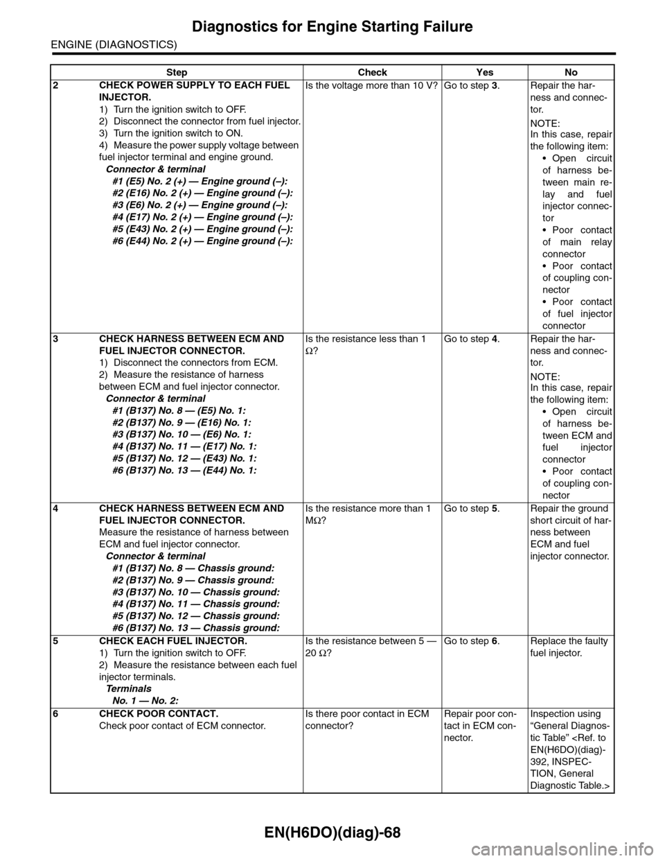
EN(H6DO)(diag)-68
Diagnostics for Engine Starting Failure
ENGINE (DIAGNOSTICS)
2CHECK POWER SUPPLY TO EACH FUEL
INJECTOR.
1) Turn the ignition switch to OFF.
2) Disconnect the connector from fuel injector.
3) Turn the ignition switch to ON.
4) Measure the power supply voltage between
fuel injector terminal and engine ground.
Connector & terminal
#1 (E5) No. 2 (+) — Engine ground (–):
#2 (E16) No. 2 (+) — Engine ground (–):
#3 (E6) No. 2 (+) — Engine ground (–):
#4 (E17) No. 2 (+) — Engine ground (–):
#5 (E43) No. 2 (+) — Engine ground (–):
#6 (E44) No. 2 (+) — Engine ground (–):
Is the voltage more than 10 V? Go to step 3.Repair the har-
ness and connec-
tor.
NOTE:In this case, repair
the following item:
•Open circuit
of harness be-
tween main re-
lay and fuel
injector connec-
tor
•Poor contact
of main relay
connector
•Poor contact
of coupling con-
nector
•Poor contact
of fuel injector
connector
3CHECK HARNESS BETWEEN ECM AND
FUEL INJECTOR CONNECTOR.
1) Disconnect the connectors from ECM.
2) Measure the resistance of harness
between ECM and fuel injector connector.
Connector & terminal
#1 (B137) No. 8 — (E5) No. 1:
#2 (B137) No. 9 — (E16) No. 1:
#3 (B137) No. 10 — (E6) No. 1:
#4 (B137) No. 11 — (E17) No. 1:
#5 (B137) No. 12 — (E43) No. 1:
#6 (B137) No. 13 — (E44) No. 1:
Is the resistance less than 1
Ω?
Go to step 4.Repair the har-
ness and connec-
tor.
NOTE:In this case, repair
the following item:
•Open circuit
of harness be-
tween ECM and
fuel injector
connector
•Poor contact
of coupling con-
nector
4CHECK HARNESS BETWEEN ECM AND
FUEL INJECTOR CONNECTOR.
Measure the resistance of harness between
ECM and fuel injector connector.
Connector & terminal
#1 (B137) No. 8 — Chassis ground:
#2 (B137) No. 9 — Chassis ground:
#3 (B137) No. 10 — Chassis ground:
#4 (B137) No. 11 — Chassis ground:
#5 (B137) No. 12 — Chassis ground:
#6 (B137) No. 13 — Chassis ground:
Is the resistance more than 1
MΩ?
Go to step 5.Repair the ground
short circuit of har-
ness between
ECM and fuel
injector connector.
5CHECK EACH FUEL INJECTOR.
1) Turn the ignition switch to OFF.
2) Measure the resistance between each fuel
injector terminals.
Te r m i n a l s
No. 1 — No. 2:
Is the resistance between 5 —
20 Ω?
Go to step 6.Replace the faulty
fuel injector.
6CHECK POOR CONTACT.
Check poor contact of ECM connector.
Is there poor contact in ECM
connector?
Repair poor con-
tact in ECM con-
nector.
Inspection using
“General Diagnos-
tic Table”
392, INSPEC-
TION, General
Diagnostic Table.>
Step Check Yes No
Page 1243 of 2453
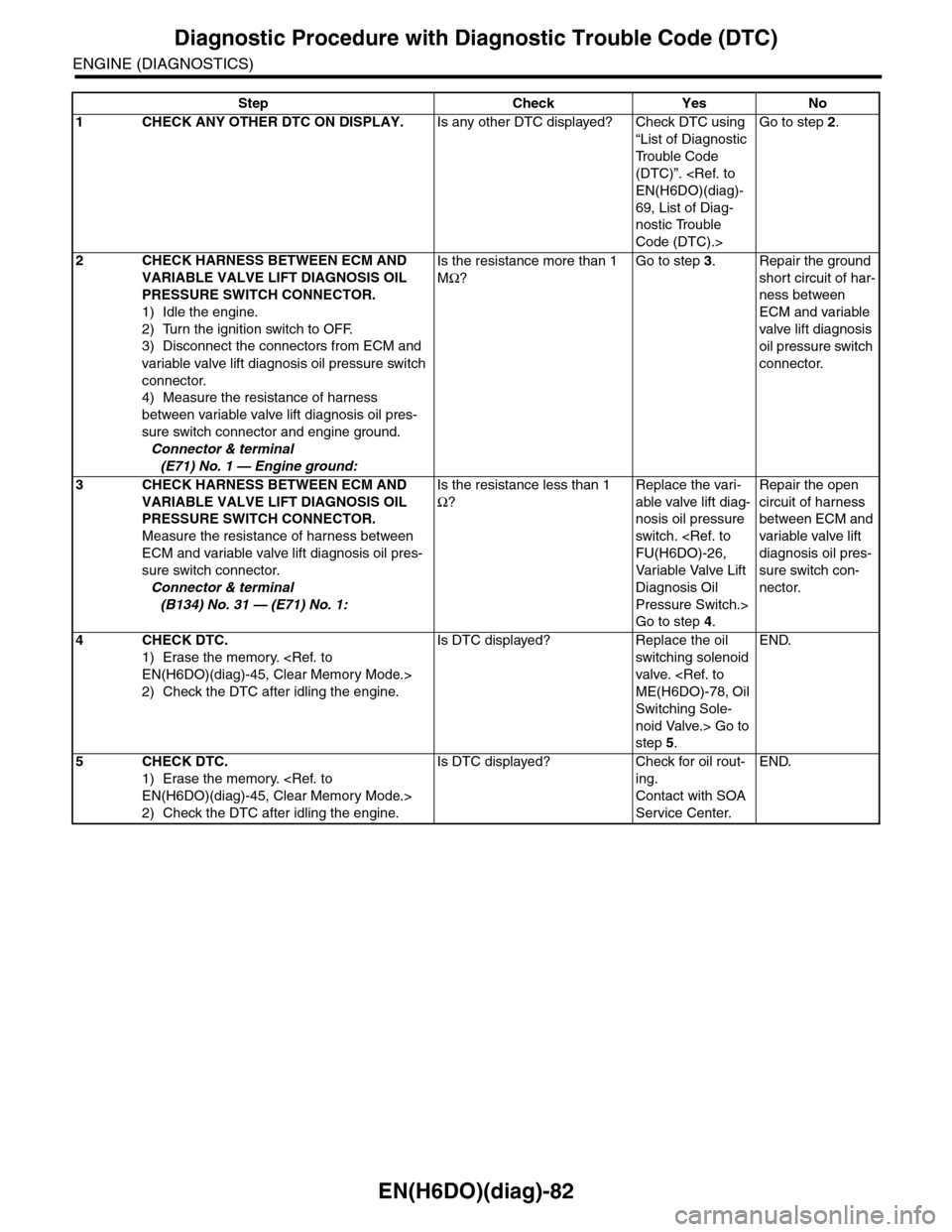
EN(H6DO)(diag)-82
Diagnostic Procedure with Diagnostic Trouble Code (DTC)
ENGINE (DIAGNOSTICS)
Step Check Yes No
1CHECK ANY OTHER DTC ON DISPLAY.Is any other DTC displayed? Check DTC using
“List of Diagnostic
Tr o u b l e C o d e
(DTC)”.
69, List of Diag-
nostic Trouble
Code (DTC).>
Go to step 2.
2CHECK HARNESS BETWEEN ECM AND
VARIABLE VALVE LIFT DIAGNOSIS OIL
PRESSURE SWITCH CONNECTOR.
1) Idle the engine.
2) Turn the ignition switch to OFF.
3) Disconnect the connectors from ECM and
variable valve lift diagnosis oil pressure switch
connector.
4) Measure the resistance of harness
between variable valve lift diagnosis oil pres-
sure switch connector and engine ground.
Connector & terminal
(E71) No. 1 — Engine ground:
Is the resistance more than 1
MΩ?
Go to step 3.Repair the ground
short circuit of har-
ness between
ECM and variable
valve lift diagnosis
oil pressure switch
connector.
3CHECK HARNESS BETWEEN ECM AND
VARIABLE VALVE LIFT DIAGNOSIS OIL
PRESSURE SWITCH CONNECTOR.
Measure the resistance of harness between
ECM and variable valve lift diagnosis oil pres-
sure switch connector.
Connector & terminal
(B134) No. 31 — (E71) No. 1:
Is the resistance less than 1
Ω?
Replace the vari-
able valve lift diag-
nosis oil pressure
switch.
Va r i a bl e Va l ve L i f t
Diagnosis Oil
Pressure Switch.>
Go to step 4.
Repair the open
circuit of harness
between ECM and
variable valve lift
diagnosis oil pres-
sure switch con-
nector.
4CHECK DTC.
1) Erase the memory.
2) Check the DTC after idling the engine.
Is DTC displayed? Replace the oil
switching solenoid
valve.
Switching Sole-
noid Valve.> Go to
step 5.
END.
5CHECK DTC.
1) Erase the memory.
2) Check the DTC after idling the engine.
Is DTC displayed? Check for oil rout-
ing.
Contact with SOA
Service Center.
END.
Page 1245 of 2453
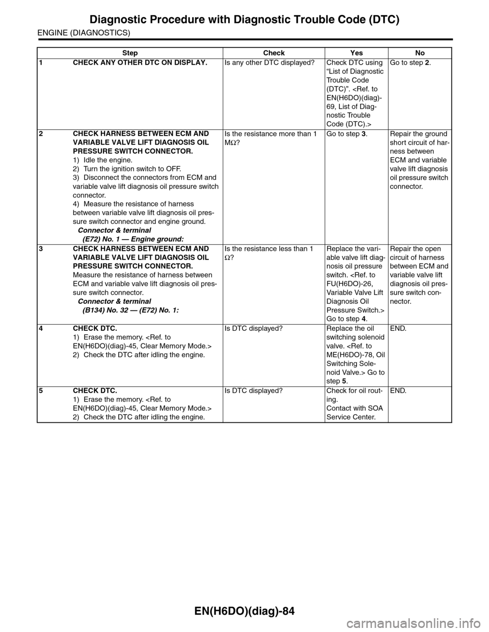
EN(H6DO)(diag)-84
Diagnostic Procedure with Diagnostic Trouble Code (DTC)
ENGINE (DIAGNOSTICS)
Step Check Yes No
1CHECK ANY OTHER DTC ON DISPLAY.Is any other DTC displayed? Check DTC using
“List of Diagnostic
Tr o u b l e C o d e
(DTC)”.
69, List of Diag-
nostic Trouble
Code (DTC).>
Go to step 2.
2CHECK HARNESS BETWEEN ECM AND
VARIABLE VALVE LIFT DIAGNOSIS OIL
PRESSURE SWITCH CONNECTOR.
1) Idle the engine.
2) Turn the ignition switch to OFF.
3) Disconnect the connectors from ECM and
variable valve lift diagnosis oil pressure switch
connector.
4) Measure the resistance of harness
between variable valve lift diagnosis oil pres-
sure switch connector and engine ground.
Connector & terminal
(E72) No. 1 — Engine ground:
Is the resistance more than 1
MΩ?
Go to step 3.Repair the ground
short circuit of har-
ness between
ECM and variable
valve lift diagnosis
oil pressure switch
connector.
3CHECK HARNESS BETWEEN ECM AND
VARIABLE VALVE LIFT DIAGNOSIS OIL
PRESSURE SWITCH CONNECTOR.
Measure the resistance of harness between
ECM and variable valve lift diagnosis oil pres-
sure switch connector.
Connector & terminal
(B134) No. 32 — (E72) No. 1:
Is the resistance less than 1
Ω?
Replace the vari-
able valve lift diag-
nosis oil pressure
switch.
Va r i a bl e Va l ve L i f t
Diagnosis Oil
Pressure Switch.>
Go to step 4.
Repair the open
circuit of harness
between ECM and
variable valve lift
diagnosis oil pres-
sure switch con-
nector.
4CHECK DTC.
1) Erase the memory.
2) Check the DTC after idling the engine.
Is DTC displayed? Replace the oil
switching solenoid
valve.
Switching Sole-
noid Valve.> Go to
step 5.
END.
5CHECK DTC.
1) Erase the memory.
2) Check the DTC after idling the engine.
Is DTC displayed? Check for oil rout-
ing.
Contact with SOA
Service Center.
END.
Page 1248 of 2453
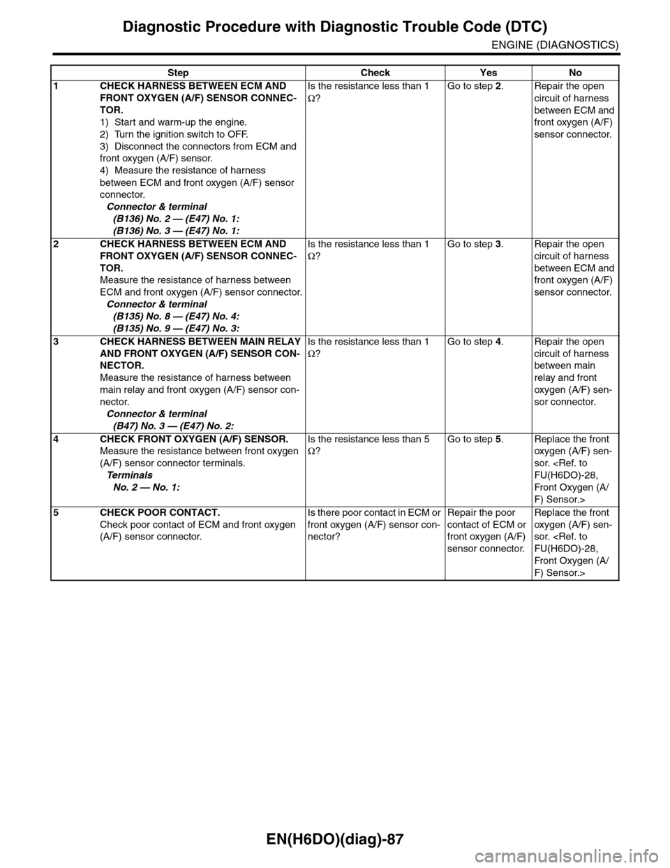
EN(H6DO)(diag)-87
Diagnostic Procedure with Diagnostic Trouble Code (DTC)
ENGINE (DIAGNOSTICS)
Step Check Yes No
1CHECK HARNESS BETWEEN ECM AND
FRONT OXYGEN (A/F) SENSOR CONNEC-
TOR.
1) Start and warm-up the engine.
2) Turn the ignition switch to OFF.
3) Disconnect the connectors from ECM and
front oxygen (A/F) sensor.
4) Measure the resistance of harness
between ECM and front oxygen (A/F) sensor
connector.
Connector & terminal
(B136) No. 2 — (E47) No. 1:
(B136) No. 3 — (E47) No. 1:
Is the resistance less than 1
Ω?
Go to step 2.Repair the open
circuit of harness
between ECM and
front oxygen (A/F)
sensor connector.
2CHECK HARNESS BETWEEN ECM AND
FRONT OXYGEN (A/F) SENSOR CONNEC-
TOR.
Measure the resistance of harness between
ECM and front oxygen (A/F) sensor connector.
Connector & terminal
(B135) No. 8 — (E47) No. 4:
(B135) No. 9 — (E47) No. 3:
Is the resistance less than 1
Ω?
Go to step 3.Repair the open
circuit of harness
between ECM and
front oxygen (A/F)
sensor connector.
3CHECK HARNESS BETWEEN MAIN RELAY
AND FRONT OXYGEN (A/F) SENSOR CON-
NECTOR.
Measure the resistance of harness between
main relay and front oxygen (A/F) sensor con-
nector.
Connector & terminal
(B47) No. 3 — (E47) No. 2:
Is the resistance less than 1
Ω?
Go to step 4.Repair the open
circuit of harness
between main
relay and front
oxygen (A/F) sen-
sor connector.
4CHECK FRONT OXYGEN (A/F) SENSOR.
Measure the resistance between front oxygen
(A/F) sensor connector terminals.
Te r m i n a l s
No. 2 — No. 1:
Is the resistance less than 5
Ω?
Go to step 5.Replace the front
oxygen (A/F) sen-
sor.
Fr o nt Ox yg en ( A /
F) Sensor.>
5CHECK POOR CONTACT.
Check poor contact of ECM and front oxygen
(A/F) sensor connector.
Is there poor contact in ECM or
front oxygen (A/F) sensor con-
nector?
Repair the poor
contact of ECM or
front oxygen (A/F)
sensor connector.
Replace the front
oxygen (A/F) sen-
sor.
Fr o nt Ox yg en ( A /
F) Sensor.>