Page 1301 of 2453
EN(H6DO)(diag)-140
Diagnostic Procedure with Diagnostic Trouble Code (DTC)
ENGINE (DIAGNOSTICS)
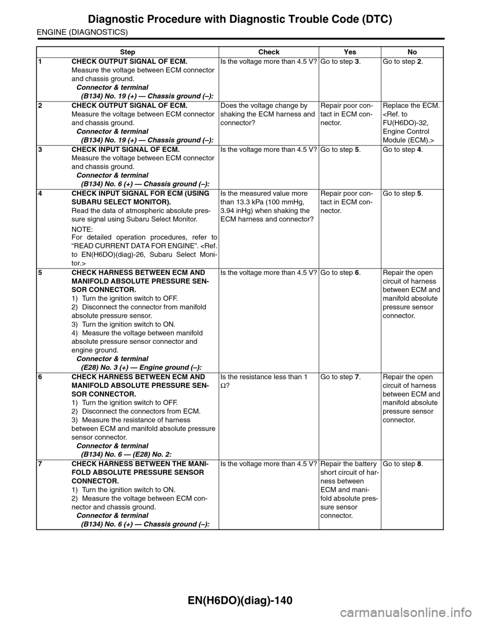
Step Check Yes No
1CHECK OUTPUT SIGNAL OF ECM.
Measure the voltage between ECM connector
and chassis ground.
Connector & terminal
(B134) No. 19 (+) — Chassis ground (–):
Is the voltage more than 4.5 V? Go to step 3.Go to step 2.
2CHECK OUTPUT SIGNAL OF ECM.
Measure the voltage between ECM connector
and chassis ground.
Connector & terminal
(B134) No. 19 (+) — Chassis ground (–):
Does the voltage change by
shaking the ECM harness and
connector?
Repair poor con-
tact in ECM con-
nector.
Replace the ECM.
FU(H6DO)-32,
Engine Control
Module (ECM).>
3CHECK INPUT SIGNAL OF ECM.
Measure the voltage between ECM connector
and chassis ground.
Connector & terminal
(B134) No. 6 (+) — Chassis ground (–):
Is the voltage more than 4.5 V? Go to step 5.Go to step 4.
4CHECK INPUT SIGNAL FOR ECM (USING
SUBARU SELECT MONITOR).
Read the data of atmospheric absolute pres-
sure signal using Subaru Select Monitor.
NOTE:For detailed operation procedures, refer to
“READ CURRENT DATA FOR ENGINE”.
to EN(H6DO)(diag)-26, Subaru Select Moni-
tor.>
Is the measured value more
than 13.3 kPa (100 mmHg,
3.94 inHg) when shaking the
ECM harness and connector?
Repair poor con-
tact in ECM con-
nector.
Go to step 5.
5CHECK HARNESS BETWEEN ECM AND
MANIFOLD ABSOLUTE PRESSURE SEN-
SOR CONNECTOR.
1) Turn the ignition switch to OFF.
2) Disconnect the connector from manifold
absolute pressure sensor.
3) Turn the ignition switch to ON.
4) Measure the voltage between manifold
absolute pressure sensor connector and
engine ground.
Connector & terminal
(E28) No. 3 (+) — Engine ground (–):
Is the voltage more than 4.5 V? Go to step 6.Repair the open
circuit of harness
between ECM and
manifold absolute
pressure sensor
connector.
6CHECK HARNESS BETWEEN ECM AND
MANIFOLD ABSOLUTE PRESSURE SEN-
SOR CONNECTOR.
1) Turn the ignition switch to OFF.
2) Disconnect the connectors from ECM.
3) Measure the resistance of harness
between ECM and manifold absolute pressure
sensor connector.
Connector & terminal
(B134) No. 6 — (E28) No. 2:
Is the resistance less than 1
Ω?
Go to step 7.Repair the open
circuit of harness
between ECM and
manifold absolute
pressure sensor
connector.
7CHECK HARNESS BETWEEN THE MANI-
FOLD ABSOLUTE PRESSURE SENSOR
CONNECTOR.
1) Turn the ignition switch to ON.
2) Measure the voltage between ECM con-
nector and chassis ground.
Connector & terminal
(B134) No. 6 (+) — Chassis ground (–):
Is the voltage more than 4.5 V? Repair the battery
short circuit of har-
ness between
ECM and mani-
fold absolute pres-
sure sensor
connector.
Go to step 8.
Page 1302 of 2453
EN(H6DO)(diag)-141
Diagnostic Procedure with Diagnostic Trouble Code (DTC)
ENGINE (DIAGNOSTICS)
8CHECK HARNESS BETWEEN ECM AND
MANIFOLD ABSOLUTE PRESSURE SEN-
SOR CONNECTOR.
1) Turn the ignition switch to OFF.
2) Measure the resistance of harness
between ECM and manifold absolute pressure
sensor connector.
Connector & terminal
(B134) No. 29 — (E28) No. 1:
Is the resistance less than 1
Ω?
Go to step 9.Repair the open
circuit of harness
between ECM and
manifold absolute
pressure sensor
connector.
9CHECK POOR CONTACT.
Check poor contact of manifold absolute pres-
sure sensor connector.
Is there poor contact in mani-
fold absolute pressure sensor
connector?
Repair the poor
contact of manifold
absolute pressure
sensor connector.
Replace the mani-
fold absolute pres-
sure sensor.
to FU(H6DO)-22,
Manifold Absolute
Pressure Sensor.>
Step Check Yes No
Page 1458 of 2453
EN(H6DO)(diag)-297
Diagnostic Procedure with Diagnostic Trouble Code (DTC)
ENGINE (DIAGNOSTICS)
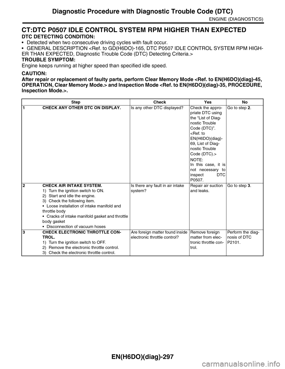
CT:DTC P0507 IDLE CONTROL SYSTEM RPM HIGHER THAN EXPECTED
DTC DETECTING CONDITION:
•Detected when two consecutive driving cycles with fault occur.
•GENERAL DESCRIPTION
ER THAN EXPECTED, Diagnostic Trouble Code (DTC) Detecting Criteria.>
TROUBLE SYMPTOM:
Engine keeps running at higher speed than specified idle speed.
CAUTION:
After repair or replacement of faulty parts, perform Clear Memory Mode
OPERATION, Clear Memory Mode.> and Inspection Mode
Inspection Mode.>.
Step Check Yes No
1CHECK ANY OTHER DTC ON DISPLAY.Is any other DTC displayed? Check the appro-
priate DTC using
the “List of Diag-
nostic Trouble
Code (DTC)”.
EN(H6DO)(diag)-
69, List of Diag-
nostic Trouble
Code (DTC).>
NOTE:In this case, it is
not necessary to
inspect DTC
P0507.
Go to step 2.
2CHECK AIR INTAKE SYSTEM.
1) Turn the ignition switch to ON.
2) Start and idle the engine.
3) Check the following item.
•Loose installation of intake manifold and
throttle body
•Cracks of intake manifold gasket and throttle
body gasket
•Disconnection of vacuum hoses
Is there any fault in air intake
system?
Repair air suction
and leaks.
Go to step 3.
3CHECK ELECTRONIC THROTTLE CON-
TROL.
1) Turn the ignition switch to OFF.
2) Remove the electronic throttle control.
3) Check the electronic throttle control.
Are foreign matter found inside
electronic throttle control?
Remove foreign
matter from elec-
tronic throttle con-
trol.
Per fo r m th e di ag -
nosis of DTC
P2101.
Page 1461 of 2453
EN(H6DO)(diag)-300
Diagnostic Procedure with Diagnostic Trouble Code (DTC)
ENGINE (DIAGNOSTICS)
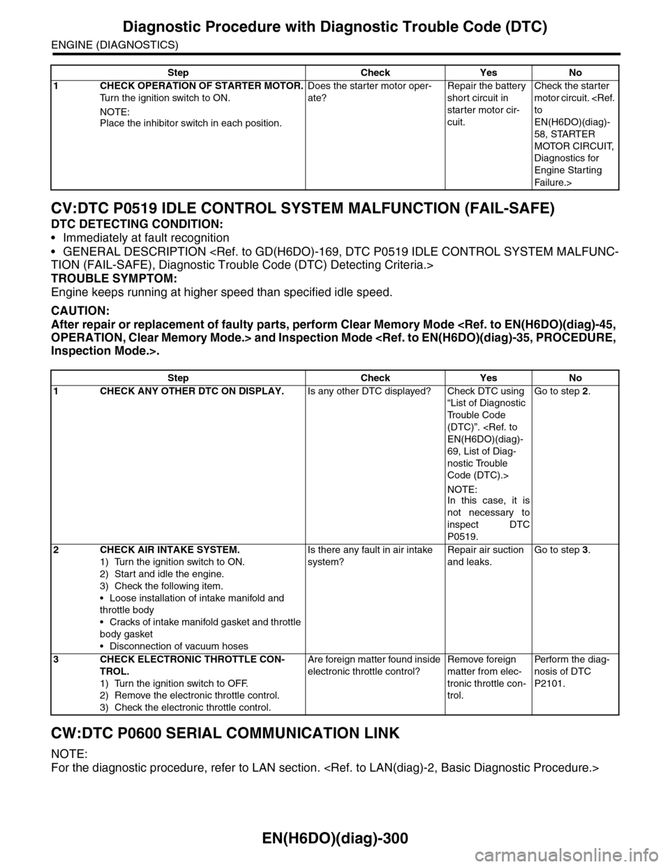
CV:DTC P0519 IDLE CONTROL SYSTEM MALFUNCTION (FAIL-SAFE)
DTC DETECTING CONDITION:
•Immediately at fault recognition
•GENERAL DESCRIPTION
TION (FAIL-SAFE), Diagnostic Trouble Code (DTC) Detecting Criteria.>
TROUBLE SYMPTOM:
Engine keeps running at higher speed than specified idle speed.
CAUTION:
After repair or replacement of faulty parts, perform Clear Memory Mode
OPERATION, Clear Memory Mode.> and Inspection Mode
Inspection Mode.>.
CW:DTC P0600 SERIAL COMMUNICATION LINK
NOTE:
For the diagnostic procedure, refer to LAN section.
Step Check Yes No
1CHECK OPERATION OF STARTER MOTOR.
Tu r n t h e i g n i t i o n s w i t c h t o O N .
NOTE:
Place the inhibitor switch in each position.
Does the starter motor oper-
ate?
Repair the battery
short circuit in
starter motor cir-
cuit.
Check the starter
motor circuit.
to
EN(H6DO)(diag)-
58, STARTER
MOTOR CIRCUIT,
Diagnostics for
Engine Starting
Fai lu r e.>
Step Check Yes No
1CHECK ANY OTHER DTC ON DISPLAY.Is any other DTC displayed? Check DTC using
“List of Diagnostic
Tr o u b l e C o d e
(DTC)”.
EN(H6DO)(diag)-
69, List of Diag-
nostic Trouble
Code (DTC).>
NOTE:In this case, it is
not necessary to
inspect DTC
P0519.
Go to step 2.
2CHECK AIR INTAKE SYSTEM.
1) Turn the ignition switch to ON.
2) Start and idle the engine.
3) Check the following item.
•Loose installation of intake manifold and
throttle body
•Cracks of intake manifold gasket and throttle
body gasket
•Disconnection of vacuum hoses
Is there any fault in air intake
system?
Repair air suction
and leaks.
Go to step 3.
3CHECK ELECTRONIC THROTTLE CON-
TROL.
1) Turn the ignition switch to OFF.
2) Remove the electronic throttle control.
3) Check the electronic throttle control.
Are foreign matter found inside
electronic throttle control?
Remove foreign
matter from elec-
tronic throttle con-
trol.
Per fo r m th e di ag -
nosis of DTC
P2101.
Page 1553 of 2453
EN(H6DO)(diag)-392
General Diagnostic Table
ENGINE (DIAGNOSTICS)
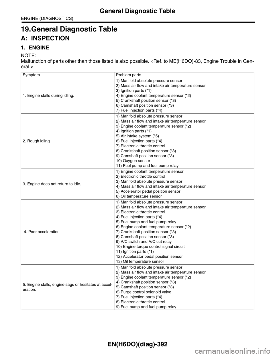
19.General Diagnostic Table
A: INSPECTION
1. ENGINE
NOTE:
Malfunction of parts other than those listed is also possible.
eral.>
Symptom Problem parts
1. Engine stalls during idling.
1) Manifold absolute pressure sensor
2) Mass air flow and intake air temperature sensor
3) Ignition parts (*1)
4) Engine coolant temperature sensor (*2)
5) Crankshaft position sensor (*3)
6) Camshaft position sensor (*3)
7) Fuel injection parts (*4)
2. Rough idling
1) Manifold absolute pressure sensor
2) Mass air flow and intake air temperature sensor
3) Engine coolant temperature sensor (*2)
4) Ignition parts (*1)
5) Air intake system (*5)
6) Fuel injection parts (*4)
7) Electronic throttle control
8) Crankshaft position sensor (*3)
9) Camshaft position sensor (*3)
10) Oxygen sensor
11) Fuel pump and fuel pump relay
3. Engine does not return to idle.
1) Engine coolant temperature sensor
2) Electronic throttle control
3) Manifold absolute pressure sensor
4) Mass air flow and intake air temperature sensor
5) Accelerator pedal position sensor
6) Oil temperature sensor
4. Poor acceleration
1) Manifold absolute pressure sensor
2) Mass air flow and intake air temperature sensor
3) Electronic throttle control
4) Fuel injection parts (*4)
5) Fuel pump and fuel pump relay
6) Engine coolant temperature sensor (*2)
7) Crankshaft position sensor (*3)
8) Camshaft position sensor (*3)
9) A/C switch and A/C cut relay
10) Engine torque control signal circuit
11) Ignition parts (*1)
12) Accelerator pedal position sensor
13) Oil temperature sensor
5. Engine stalls, engine sags or hesitates at accel-
eration.
1) Manifold absolute pressure sensor
2) Mass air flow and intake air temperature sensor
3) Engine coolant temperature sensor (*2)
4) Crankshaft position sensor (*3)
5) Camshaft position sensor (*3)
6) Purge control solenoid valve
7) Fuel injection parts (*4)
8) Electronic throttle control
9) Fuel pump and fuel pump relay
Page 1554 of 2453
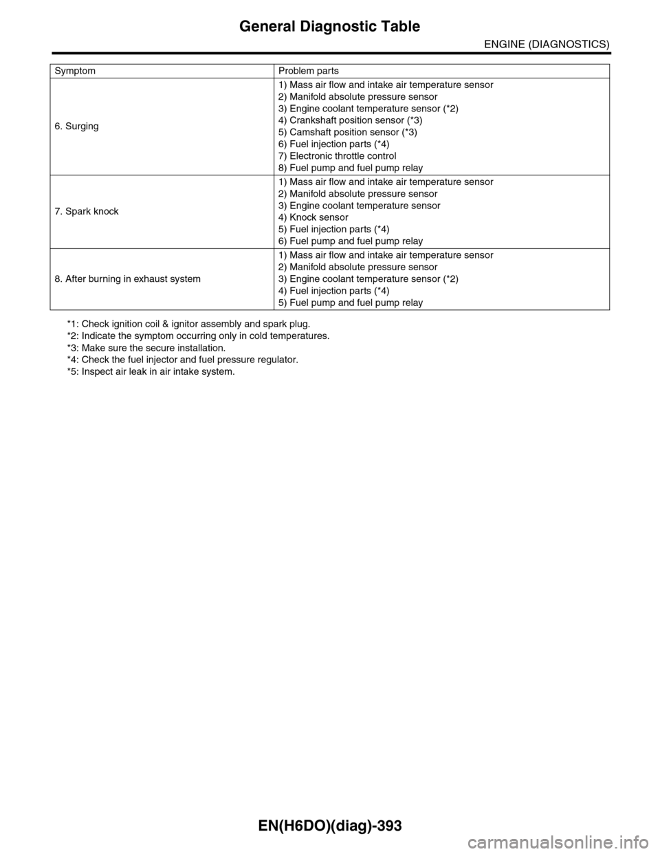
EN(H6DO)(diag)-393
General Diagnostic Table
ENGINE (DIAGNOSTICS)
*1: Check ignition coil & ignitor assembly and spark plug.
*2: Indicate the symptom occurring only in cold temperatures.
*3: Make sure the secure installation.
*4: Check the fuel injector and fuel pressure regulator.
*5: Inspect air leak in air intake system.
6. Surging
1) Mass air flow and intake air temperature sensor
2) Manifold absolute pressure sensor
3) Engine coolant temperature sensor (*2)
4) Crankshaft position sensor (*3)
5) Camshaft position sensor (*3)
6) Fuel injection parts (*4)
7) Electronic throttle control
8) Fuel pump and fuel pump relay
7. Spark knock
1) Mass air flow and intake air temperature sensor
2) Manifold absolute pressure sensor
3) Engine coolant temperature sensor
4) Knock sensor
5) Fuel injection parts (*4)
6) Fuel pump and fuel pump relay
8. After burning in exhaust system
1) Mass air flow and intake air temperature sensor
2) Manifold absolute pressure sensor
3) Engine coolant temperature sensor (*2)
4) Fuel injection parts (*4)
5) Fuel pump and fuel pump relay
Symptom Problem parts
Page 1564 of 2453
FU(H6DO)-3
General Description
FUEL INJECTION (FUEL SYSTEMS)
B: COMPONENT
1. INTAKE MANIFOLD
FU-02706
T4
T5
T4
T4
T4
T5
(5)(6)
(2)
(12)
(2)
T2
T2
T2
T3
(10)
T3
(9)
(11)
T1
T2
T2
(14)(13)
(14)
(14)(13)(14)
T1
(4)
(3)
T2
T4
(7)
(8)
(1)
Page 1565 of 2453
FU(H6DO)-4
General Description
FUEL INJECTION (FUEL SYSTEMS)
2. FUEL INJECTOR
(1) Intake manifold (8) HoseTightening torque: N·m (kgf-m, ft-lb)
(2) O-ring (9) NippleT1: 1.5 (0.15, 1.1)
(3) Manifold absolute pressure sensor (10) PlugT2: 6.4 (0.65, 4.7)
(4) Filter (11) Fuel pipe protector LHT3: 17 (1.7, 12.5)
(5) Fuel pipe protector RH (12) Fuel pipe ASSYT4: 19 (1.9, 14)
(6) Purge control solenoid valve (13) HoseT5: 25 (2.5, 18)
(7) Hose (14) Clamp
(1) Fuel injector pipe LH (4) Injection rubberTightening torque: N·m (kgf-m, ft-lb)
(2) Insulator (5) O-ringT: 19 (1.9, 14)
(3) Fuel injector (6) Fuel injector pipe RH
FU-02561
(6)
T
T
(5)
(4)
(3)
(2)
(2)(3)(4)(5)
(1)