2009 SUBARU TRIBECA Manifold
[x] Cancel search: ManifoldPage 1761 of 2453
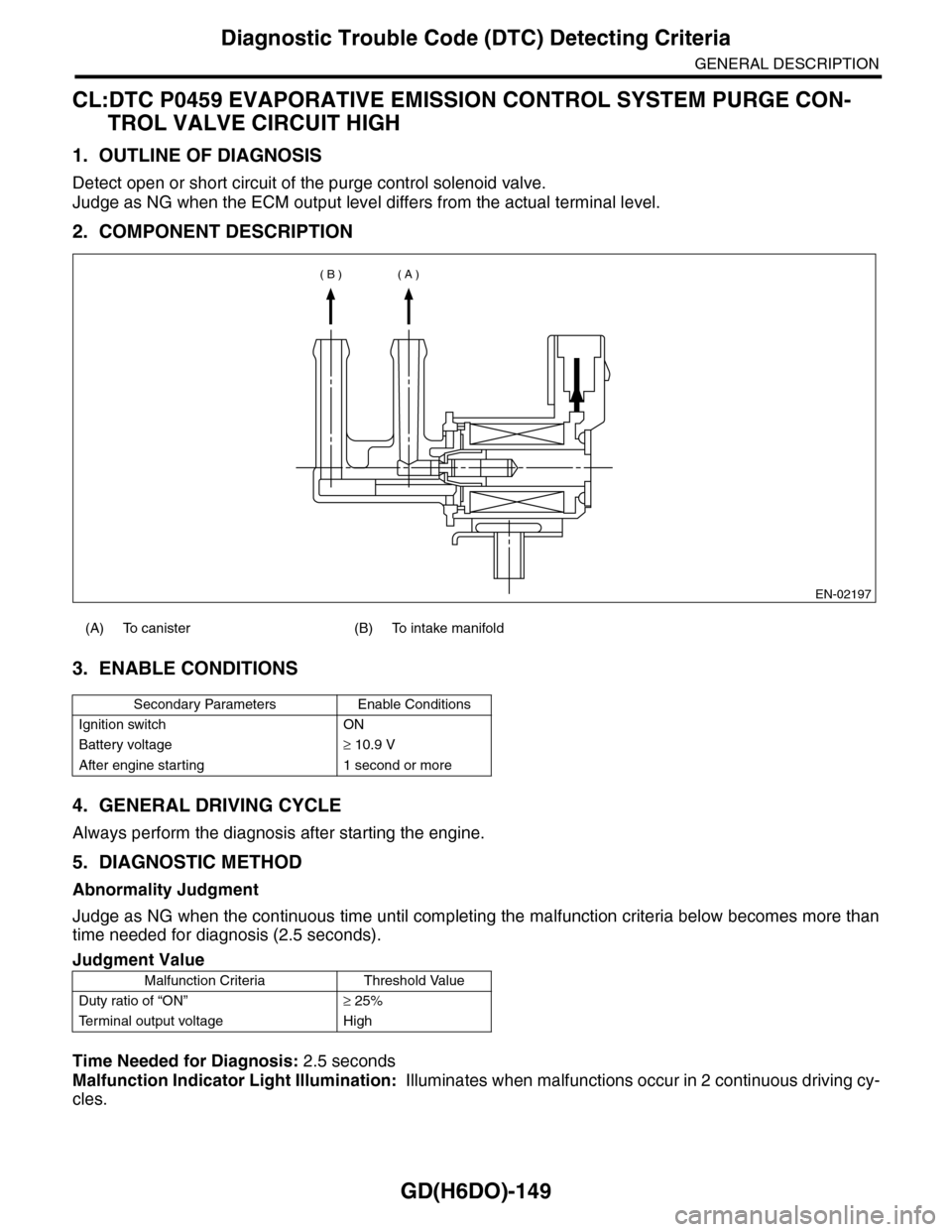
GD(H6DO)-149
Diagnostic Trouble Code (DTC) Detecting Criteria
GENERAL DESCRIPTION
CL:DTC P0459 EVAPORATIVE EMISSION CONTROL SYSTEM PURGE CON-
TROL VALVE CIRCUIT HIGH
1. OUTLINE OF DIAGNOSIS
Detect open or short circuit of the purge control solenoid valve.
Judge as NG when the ECM output level differs from the actual terminal level.
2. COMPONENT DESCRIPTION
3. ENABLE CONDITIONS
4. GENERAL DRIVING CYCLE
Always perform the diagnosis after starting the engine.
5. DIAGNOSTIC METHOD
Abnormality Judgment
Judge as NG when the continuous time until completing the malfunction criteria below becomes more than
time needed for diagnosis (2.5 seconds).
Time Needed for Diagnosis: 2.5 seconds
Malfunction Indicator Light Illumination: Illuminates when malfunctions occur in 2 continuous driving cy-
cles.
(A) To canister (B) To intake manifold
Secondary Parameters Enable Conditions
Ignition switch ON
Battery voltage≥ 10.9 V
After engine starting 1 second or more
Judgment Value
Malfunction Criteria Threshold Value
Duty ratio of “ON”≥ 25%
Te r m i n a l o u t p u t v o l t a g e H i g h
EN-02197
( A )( B )
Page 1775 of 2453
GD(H6DO)-163
Diagnostic Trouble Code (DTC) Detecting Criteria
GENERAL DESCRIPTION
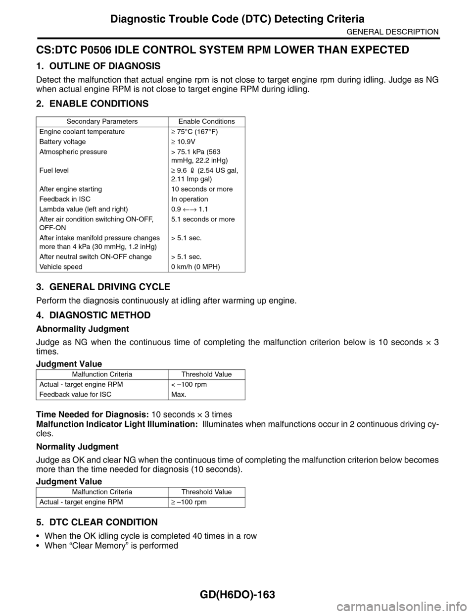
CS:DTC P0506 IDLE CONTROL SYSTEM RPM LOWER THAN EXPECTED
1. OUTLINE OF DIAGNOSIS
Detect the malfunction that actual engine rpm is not close to target engine rpm during idling. Judge as NG
when actual engine RPM is not close to target engine RPM during idling.
2. ENABLE CONDITIONS
3. GENERAL DRIVING CYCLE
Perform the diagnosis continuously at idling after warming up engine.
4. DIAGNOSTIC METHOD
Abnormality Judgment
Judge as NG when the continuous time of completing the malfunction criterion below is 10 seconds × 3
times.
Time Needed for Diagnosis: 10 seconds × 3 times
Malfunction Indicator Light Illumination: Illuminates when malfunctions occur in 2 continuous driving cy-
cles.
Normality Judgment
Judge as OK and clear NG when the continuous time of completing the malfunction criterion below becomes
more than the time needed for diagnosis (10 seconds).
5. DTC CLEAR CONDITION
•When the OK idling cycle is completed 40 times in a row
•When “Clear Memory” is performed
Secondary Parameters Enable Conditions
Engine coolant temperature≥ 75°C (167°F)
Battery voltage≥ 10.9V
Atmospheric pressure > 75.1 kPa (563
mmHg, 22.2 inHg)
Fuel level≥ 9.6 2 (2.54 US gal,
2.11 Imp gal)
After engine starting 10 seconds or more
Feedback in ISC In operation
Lambda value (left and right) 0.9 ←→ 1.1
After air condition switching ON-OFF,
OFF-ON
5.1 seconds or more
After intake manifold pressure changes
more than 4 kPa (30 mmHg, 1.2 inHg)
> 5.1 sec.
After neutral switch ON-OFF change > 5.1 sec.
Ve h i c l e s p e e d 0 k m / h ( 0 M P H )
Judgment Value
Malfunction Criteria Threshold Value
Actual - target engine RPM < –100 rpm
Feedback value for ISC Max.
Judgment Value
Malfunction Criteria Threshold Value
Actual - target engine RPM≥ –100 rpm
Page 1777 of 2453
GD(H6DO)-165
Diagnostic Trouble Code (DTC) Detecting Criteria
GENERAL DESCRIPTION
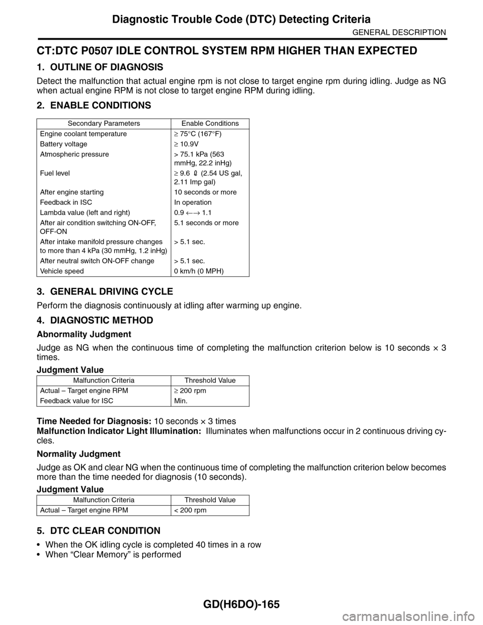
CT:DTC P0507 IDLE CONTROL SYSTEM RPM HIGHER THAN EXPECTED
1. OUTLINE OF DIAGNOSIS
Detect the malfunction that actual engine rpm is not close to target engine rpm during idling. Judge as NG
when actual engine RPM is not close to target engine RPM during idling.
2. ENABLE CONDITIONS
3. GENERAL DRIVING CYCLE
Perform the diagnosis continuously at idling after warming up engine.
4. DIAGNOSTIC METHOD
Abnormality Judgment
Judge as NG when the continuous time of completing the malfunction criterion below is 10 seconds × 3
times.
Time Needed for Diagnosis: 10 seconds × 3 times
Malfunction Indicator Light Illumination: Illuminates when malfunctions occur in 2 continuous driving cy-
cles.
Normality Judgment
Judge as OK and clear NG when the continuous time of completing the malfunction criterion below becomes
more than the time needed for diagnosis (10 seconds).
5. DTC CLEAR CONDITION
•When the OK idling cycle is completed 40 times in a row
•When “Clear Memory” is performed
Secondary Parameters Enable Conditions
Engine coolant temperature≥ 75°C (167°F)
Battery voltage≥ 10.9V
Atmospheric pressure > 75.1 kPa (563
mmHg, 22.2 inHg)
Fuel level≥ 9.6 2 (2.54 US gal,
2.11 Imp gal)
After engine starting 10 seconds or more
Feedback in ISC In operation
Lambda value (left and right) 0.9 ←→ 1.1
After air condition switching ON-OFF,
OFF-ON
5.1 seconds or more
After intake manifold pressure changes
to more than 4 kPa (30 mmHg, 1.2 inHg)
> 5.1 sec.
After neutral switch ON-OFF change > 5.1 sec.
Ve h i c l e s p e e d 0 k m / h ( 0 M P H )
Judgment Value
Malfunction Criteria Threshold Value
Actual – Target engine RPM≥ 200 rpm
Feedback value for ISC Min.
Judgment Value
Malfunction Criteria Threshold Value
Actual – Target engine RPM < 200 rpm
Page 1801 of 2453
GD(H6DO)-189
Diagnostic Trouble Code (DTC) Detecting Criteria
GENERAL DESCRIPTION
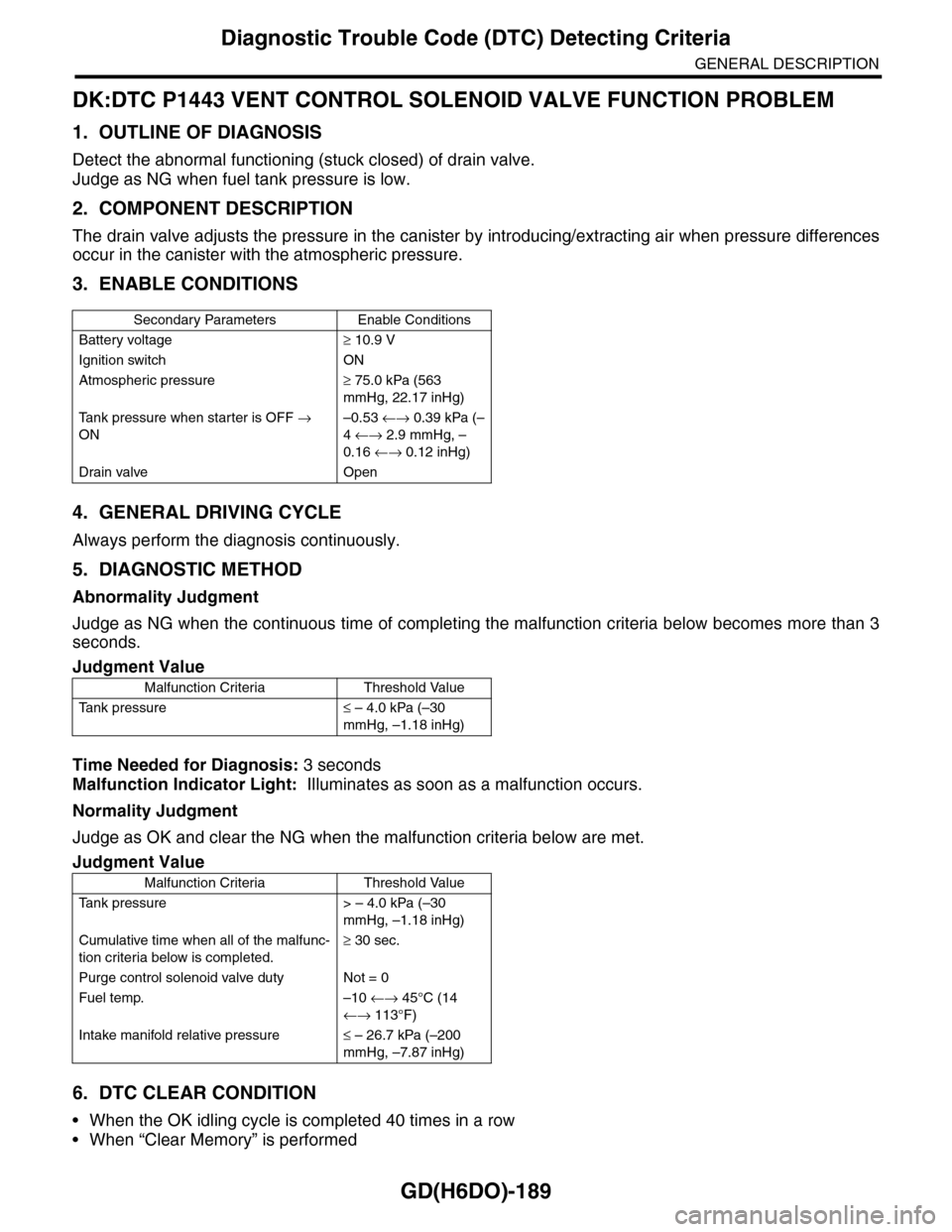
DK:DTC P1443 VENT CONTROL SOLENOID VALVE FUNCTION PROBLEM
1. OUTLINE OF DIAGNOSIS
Detect the abnormal functioning (stuck closed) of drain valve.
Judge as NG when fuel tank pressure is low.
2. COMPONENT DESCRIPTION
The drain valve adjusts the pressure in the canister by introducing/extracting air when pressure differences
occur in the canister with the atmospheric pressure.
3. ENABLE CONDITIONS
4. GENERAL DRIVING CYCLE
Always perform the diagnosis continuously.
5. DIAGNOSTIC METHOD
Abnormality Judgment
Judge as NG when the continuous time of completing the malfunction criteria below becomes more than 3
seconds.
Time Needed for Diagnosis: 3 seconds
Malfunction Indicator Light: Illuminates as soon as a malfunction occurs.
Normality Judgment
Judge as OK and clear the NG when the malfunction criteria below are met.
6. DTC CLEAR CONDITION
•When the OK idling cycle is completed 40 times in a row
•When “Clear Memory” is performed
Secondary Parameters Enable Conditions
Battery voltage≥ 10.9 V
Ignition switch ON
Atmospheric pressure≥ 75.0 kPa (563
mmHg, 22.17 inHg)
Ta n k p r e s s u r e w h e n s t a r t e r i s O F F →
ON
–0.53 ←→ 0.39 kPa (–
4 ←→ 2.9 mmHg, –
0.16 ←→ 0.12 inHg)
Drain valve Open
Judgment Value
Malfunction Criteria Threshold Value
Ta n k p r e s s u r e≤ – 4.0 kPa (–30
mmHg, –1.18 inHg)
Judgment Value
Malfunction Criteria Threshold Value
Ta n k p r e s s u r e > – 4 . 0 k P a ( – 3 0
mmHg, –1.18 inHg)
Cumulative time when all of the malfunc-
tion criteria below is completed.
≥ 30 sec.
Purge control solenoid valve duty Not = 0
Fuel temp. –10 ←→ 45°C (14
←→ 113°F)
Intake manifold relative pressure≤ – 26.7 kPa (–200
mmHg, –7.87 inHg)
Page 1833 of 2453
GD(H6DO)-221
Diagnostic Trouble Code (DTC) Detecting Criteria
GENERAL DESCRIPTION
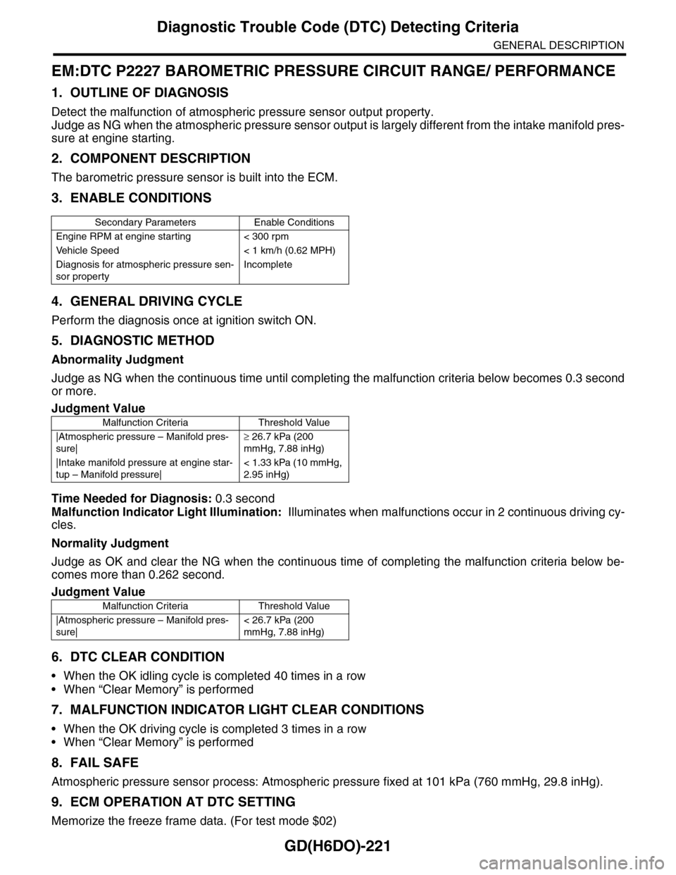
EM:DTC P2227 BAROMETRIC PRESSURE CIRCUIT RANGE/ PERFORMANCE
1. OUTLINE OF DIAGNOSIS
Detect the malfunction of atmospheric pressure sensor output property.
Judge as NG when the atmospheric pressure sensor output is largely different from the intake manifold pres-
sure at engine starting.
2. COMPONENT DESCRIPTION
The barometric pressure sensor is built into the ECM.
3. ENABLE CONDITIONS
4. GENERAL DRIVING CYCLE
Perform the diagnosis once at ignition switch ON.
5. DIAGNOSTIC METHOD
Abnormality Judgment
Judge as NG when the continuous time until completing the malfunction criteria below becomes 0.3 second
or more.
Time Needed for Diagnosis: 0.3 second
Malfunction Indicator Light Illumination: Illuminates when malfunctions occur in 2 continuous driving cy-
cles.
Normality Judgment
Judge as OK and clear the NG when the continuous time of completing the malfunction criteria below be-
comes more than 0.262 second.
6. DTC CLEAR CONDITION
•When the OK idling cycle is completed 40 times in a row
•When “Clear Memory” is performed
7. MALFUNCTION INDICATOR LIGHT CLEAR CONDITIONS
•When the OK driving cycle is completed 3 times in a row
•When “Clear Memory” is performed
8. FAIL SAFE
Atmospheric pressure sensor process: Atmospheric pressure fixed at 101 kPa (760 mmHg, 29.8 inHg).
9. ECM OPERATION AT DTC SETTING
Memorize the freeze frame data. (For test mode $02)
Secondary Parameters Enable Conditions
Engine RPM at engine starting < 300 rpm
Ve h i c l e S p e e d < 1 k m / h ( 0 . 6 2 M P H )
Diagnosis for atmospheric pressure sen-
sor property
Incomplete
Judgment Value
Malfunction Criteria Threshold Value
|Atmospheric pressure – Manifold pres-
sure|
≥ 26.7 kPa (200
mmHg, 7.88 inHg)
|Intake manifold pressure at engine star-
tup – Manifold pressure|
< 1.33 kPa (10 mmHg,
2.95 inHg)
Judgment Value
Malfunction Criteria Threshold Value
|Atmospheric pressure – Manifold pres-
sure|
< 26.7 kPa (200
mmHg, 7.88 inHg)
Page 1890 of 2453
ME(H6DO)-24
Intake Manifold Vacuum
MECHANICAL
5. Intake Manifold Vacuum
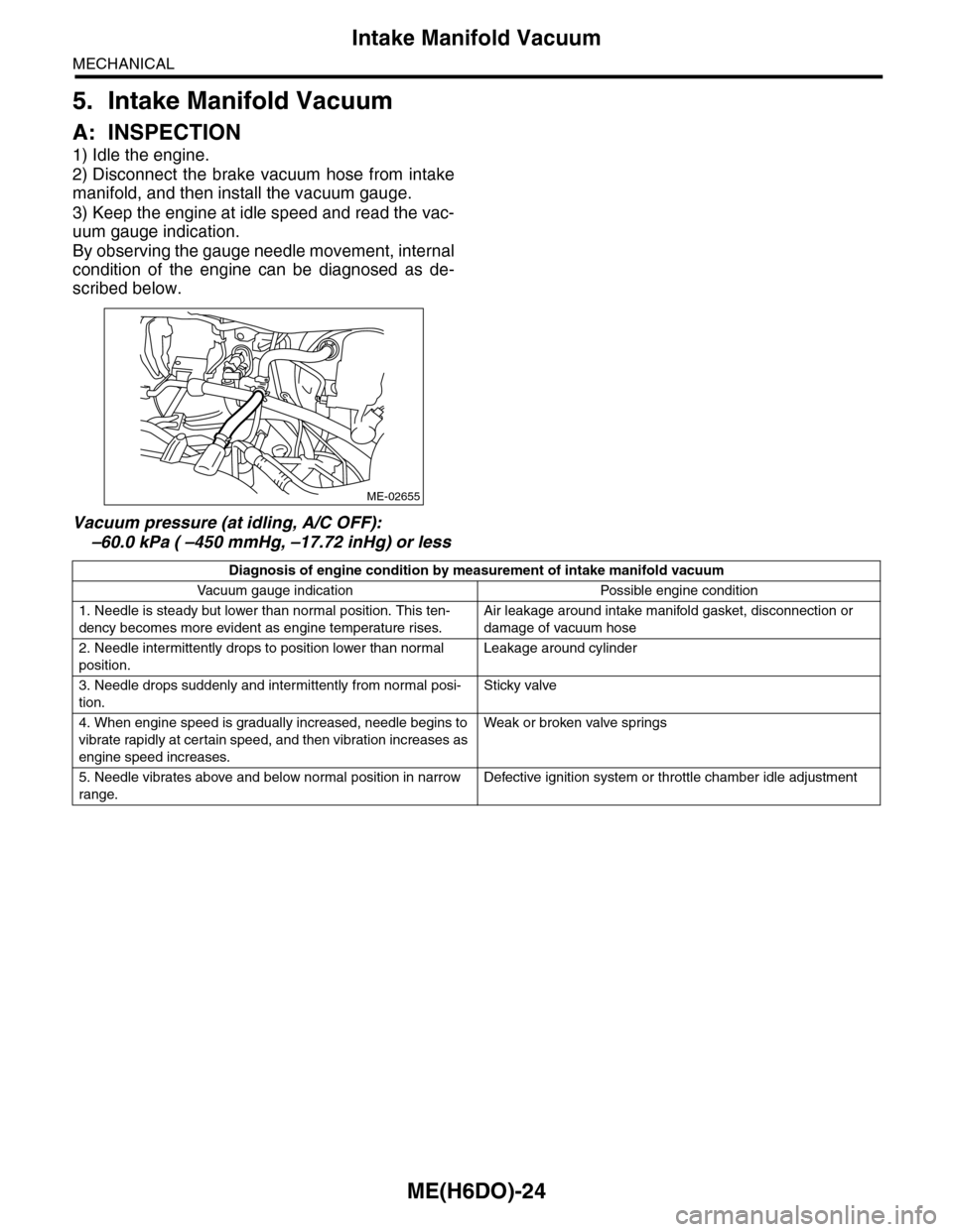
A: INSPECTION
1) Idle the engine.
2) Disconnect the brake vacuum hose from intake
manifold, and then install the vacuum gauge.
3) Keep the engine at idle speed and read the vac-
uum gauge indication.
By observing the gauge needle movement, internal
condition of the engine can be diagnosed as de-
scribed below.
Vacuum pressure (at idling, A/C OFF):
–60.0 kPa ( –450 mmHg, –17.72 inHg) or less
ME-02655
Diagnosis of engine condition by measurement of intake manifold vacuum
Va c u u m g a u g e i n d i c a t i o n Po s s i bl e e n g i n e c o n d i t i o n
1. Needle is steady but lower than normal position. This ten-
dency becomes more evident as engine temperature rises.
Air leakage around intake manifold gasket, disconnection or
damage of vacuum hose
2. Needle intermittently drops to position lower than normal
position.
Leakage around cylinder
3. Needle drops suddenly and intermittently from normal posi-
tion.
Sticky valve
4. When engine speed is gradually increased, needle begins to
vibrate rapidly at certain speed, and then vibration increases as
engine speed increases.
Weak or broken valve spr ings
5. Needle vibrates above and below normal position in narrow
range.
Defective ignition system or throttle chamber idle adjustment
Page 1906 of 2453
ME(H6DO)-40
Preparation for Overhaul
MECHANICAL
12.Preparation for Overhaul
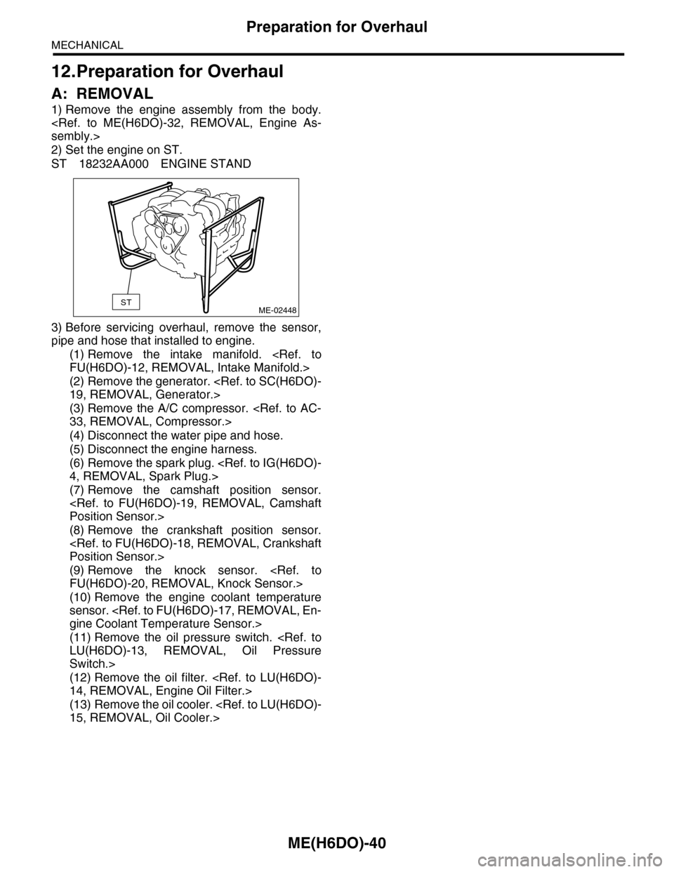
A: REMOVAL
1) Remove the engine assembly from the body.
2) Set the engine on ST.
ST 18232AA000 ENGINE STAND
3) Before servicing overhaul, remove the sensor,
pipe and hose that installed to engine.
(1) Remove the intake manifold.
(2) Remove the generator.
(3) Remove the A/C compressor.
(4) Disconnect the water pipe and hose.
(5) Disconnect the engine harness.
(6) Remove the spark plug.
(7) Remove the camshaft position sensor.
(8) Remove the crankshaft position sensor.
(9) Remove the knock sensor.
(10) Remove the engine coolant temperature
sensor.
(11) Remove the oil pressure switch.
Switch.>
(12) Remove the oil filter.
(13) Remove the oil cooler.
STME-02448
Page 1950 of 2453
ME(H6DO)-84
Engine Trouble in General
MECHANICAL
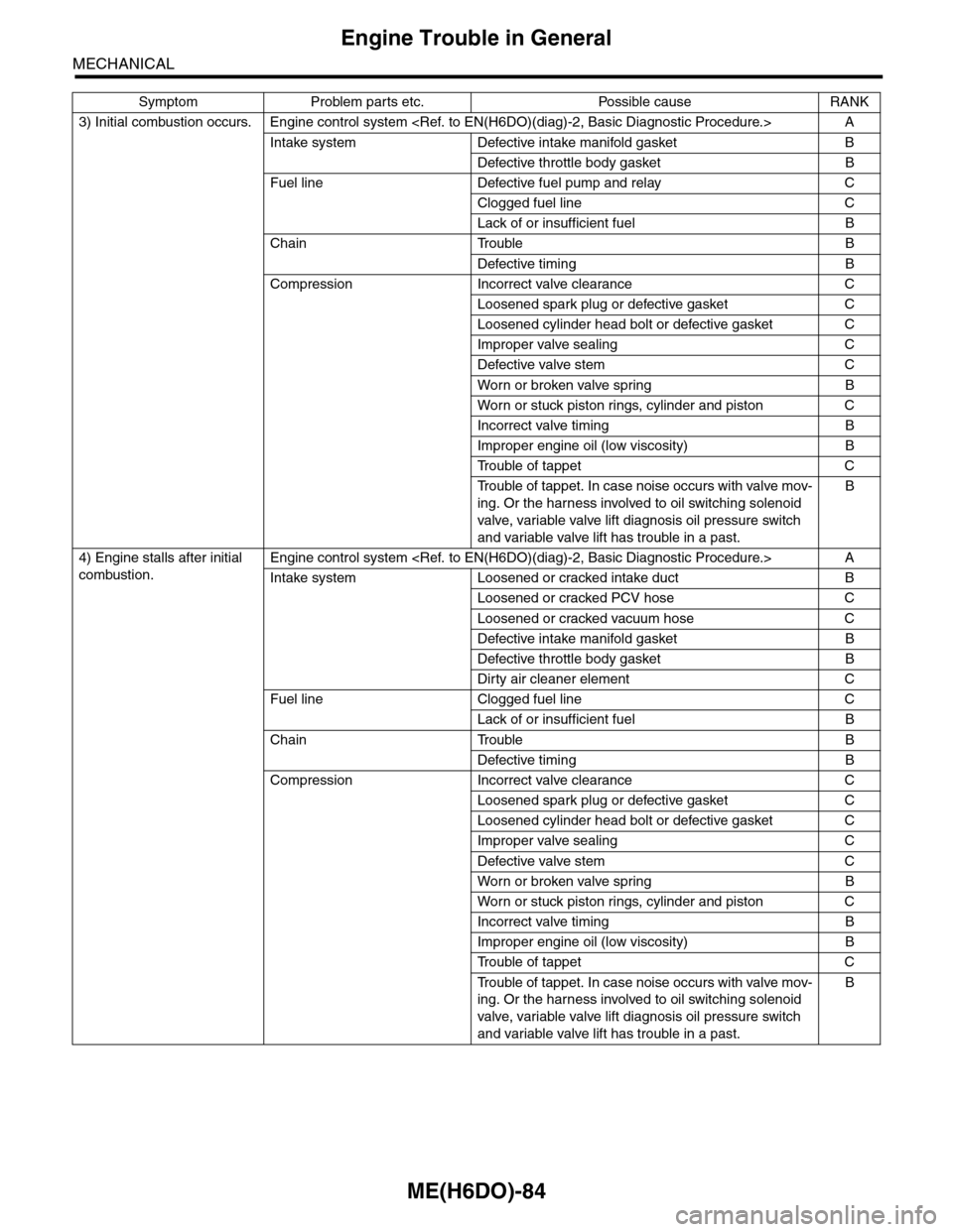
3) Initial combustion occurs. Engine control system
Intake system Defective intake manifold gasket B
Defective throttle body gasket B
Fuel line Defective fuel pump and relay C
Clogged fuel line C
Lack of or insufficient fuel B
Chain Trouble B
Defective timing B
Compression Incorrect valve clearance C
Loosened spark plug or defective gasket C
Loosened cylinder head bolt or defective gasket C
Improper valve sealing C
Defective valve stem C
Wor n or broken valve spr ing B
Wor n or stuck piston r ings, cylinder and piston C
Incorrect valve timing B
Improper engine oil (low viscosity) B
Tr o u b l e o f t a p p e t C
Tr o u b l e o f t a p p e t . I n c a s e n o i s e o c c u r s w i t h v a l v e m o v -
ing. Or the harness involved to oil switching solenoid
valve, variable valve lift diagnosis oil pressure switch
and variable valve lift has trouble in a past.
B
4) Engine stalls after initial
combustion.
Engine control system
Intake system Loosened or cracked intake duct B
Loosened or cracked PCV hose C
Loosened or cracked vacuum hose C
Defective intake manifold gasket B
Defective throttle body gasket B
Dirty air cleaner element C
Fuel line Clogged fuel line C
Lack of or insufficient fuel B
Chain Trouble B
Defective timing B
Compression Incorrect valve clearance C
Loosened spark plug or defective gasket C
Loosened cylinder head bolt or defective gasket C
Improper valve sealing C
Defective valve stem C
Wor n or broken valve spr ing B
Wor n or stuck piston r ings, cylinder and piston C
Incorrect valve timing B
Improper engine oil (low viscosity) B
Tr o u b l e o f t a p p e t C
Tr o u b l e o f t a p p e t . I n c a s e n o i s e o c c u r s w i t h v a l v e m o v -
ing. Or the harness involved to oil switching solenoid
valve, variable valve lift diagnosis oil pressure switch
and variable valve lift has trouble in a past.
B
Symptom Problem parts etc. Possible cause RANK