2009 SUBARU TRIBECA Manifold
[x] Cancel search: ManifoldPage 340 of 2453

AC-14
General Description
HVAC SYSTEM (HEATER, VENTILATOR AND A/C)
C: CAUTION
1. HFC-134A A/C SYSTEM
•The cooling system components for the HFC-
134a system such as the refrigerant and compres-
sor oil are different from the conventional CFC-12
system components and they are incompatible with
each other.
•Vehicles with the HFC-134a system can be iden-
tified by the label (A) attached to the vehicle.
Before maintenance, check which A/C system is in-
stalled to the vehicle.
2. COMPRESSOR OIL
•HFC-134a compressor oil has no compatibility
with that of CFC-12 system.
•Use only Denso Oil 8, the manufacturer-autho-
rized compressor oil for the HFC-134a system.
•Do not mix multiple compressor oils.
If CFC-12 compressor oil is used in the HFC-134a
A/C system, the compressor may become stuck
due to poor lubrication, or the refrigerant may leak
due to swelling of rubber parts.
On the other hand, if HFC-134a compressor oil is
used in a CFC-12 A/C system, the durability of the
A/C system will be lowered.
•HFC-134a compressor oil is very hygroscopic.
When replacing or installing/removing A/C parts,
immediately isolate the oil from atmosphere using a
plug or tape. In order to avoid moisture, store the oil
in a container with its cap tightly closed.
3. REFRIGERANT
•CFC-12 refrigerant cannot be used in a HFC-
134a A/C system. HFC-134a refrigerant, also can-
not be used in a CFC-12 A/C system.
•If an incorrect or no refrigerant is used, it will re-
sult in poor lubrication and the compressor itself
may be damaged.
4. HANDLING OF REFRIGERANT
•The refrigerant boils at approx. –30°C (22°F).
When handling it, be sure to wear protective gog-
gles and protective gloves. Direct contact of the re-
frigerant with skin may cause frostbite.
If the refrigerant gets into your eye, avoid rubbing
your eyes with your hands. Wash your eye with
plenty of water, and receive medical treatment from
an eye doctor.
•Do not heat a service can. If a service can is di-
rectly heated, or put into boiling water, the inside
pressure will become extremely high. This may
cause the can to explode. If a service can must be
warmed up, use warm water of 40°C (104°F) or less.
•Do not drop or subject a service can to impacts.
(Observe the precautions and operation procedure
described on the refrigerant can.)
•When the engine is running, do not open the
high-pressure valve of the manifold gauge. High-
pressure gas can back-flow resulting in an explo-
sion of the can.
•Provide good ventilation and do not work in a
closed area.
•In order to prevent global warming, avoid releas-
ing HFC-134a into the atmosphere. Using a refrig-
erant recovery system, discharge and recycle the
gas.
AC-01380
(A) Goggles
(B) Gloves
(C) Avoid open flame
(D) No direct heat on container
(E) Do not discharge
(F) Loosen
(A)(B)
(C) (D)
(E)
(F)
AC-00007
Page 343 of 2453

AC-17
General Description
HVAC SYSTEM (HEATER, VENTILATOR AND A/C)
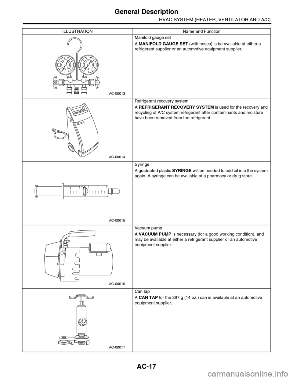
Manifold gauge set
A MANIFOLD GAUGE SET (with hoses) is be available at either a
refrigerant supplier or an automotive equipment supplier.
Refrigerant recovery system
A REFRIGERANT RECOVERY SYSTEM is used for the recovery and
recycling of A/C system refrigerant after contaminants and moisture
have been removed from the refrigerant.
Syringe
A graduated plastic SYRINGE will be needed to add oil into the system
again. A syringe can be available at a pharmacy or drug store.
Va c u u m p u m p
A VACUUM PUMP is necessary (for a good working condition), and
may be available at either a refrigerant supplier or an automotive
equipment supplier.
Can tap
A CAN TAP for the 397 g (14 oz.) can is available at an automotive
equipment supplier.
ILLUSTRATION Name and Function
AC-00013
AC-00014
AC-00015
AC-00016
AC-00017
Page 345 of 2453

AC-19
Refrigerant Pressure with Manifold Gauge Set
HVAC SYSTEM (HEATER, VENTILATOR AND A/C)
2. Refrigerant Pressure with Manifold Gauge Set
A: PROCEDURE
1) Place the vehicle in the shade and windless condition.
2) Connect the manifold gauge set.
3) Open all windows and close all doors.
4) Increase the engine to 1,500 rpm.
5) Turn on the A/C switch.
6) Turn the temperature control switch to MAX COOL.
7) Put in RECIRC position.
8) Turn the blower control switch to HI.
9) Read the gauge.
Standard:
Low pressure: 127 — 196 kPa (1.3 — 2.0 kg/cm2, 18 — 28 psi)
High pressure: 1,471 — 1,667 kPa (15 — 17 kg/cm2, 213 — 242 psi)
Ambient temperature: 30 — 35°C (86—95°F)
B: INSPECTION
Symptom Probable cause Repair order
High-pressure side is unusually high.
•Defective condenser fan motor
•Clogged condenser fin
•Too much refrigerant
•Air inside the system
•Defective receiver dryer
•Replace the fan motor.
•Clean the condenser fin.
•Discharge refrigerant.
•Replace the receiver dryer.
•After evacuating again, charge an
appropriate amount of refrigerant.
High-pressure side is unusually low.
•Defective compressor
•Not enough refrigerant
•Clogged expansion valve
•Expansion valve frozen temporarily by
moisture.
•Replace the compressor.
•Check for leaks.
•Replace the expansion valve.
•Fully evacuate the expansion valve.
Low-pressure side is unusually high.
•Defective compressor
•Defective expansion valve
•Too much refrigerant
•Replace the compressor.
•Replace the expansion valve.
•Discharge refrigerant.
Low-pressure side is unusually low.
•Not enough refrigerant
•Clogged expansion valve
•Expansion valve frozen temporarily by
moisture.
•Saturated receiver dryer
•Check for leaks.
•Replace the expansion valve.
•Replace the receiver dryer.
Page 346 of 2453

AC-20
Refrigerant Recovery Procedure
HVAC SYSTEM (HEATER, VENTILATOR AND A/C)
3. Refrigerant Recovery Proce-
dure
A: PROCEDURE
CAUTION:
•During operation, be sure to wear protective
goggles and protective gloves.
•Connect the refrigerant recovery system with
the manifold gauge set to discharge the refrig-
erant from the A/C system and recycle the gas.
•When recycling the discharged refrigerant,
keep service cans on hand. Because the recov-
ery rate with the recovery system is approx.
90%, service cans are necessary to charge the
refrigerant.
•Follow the detailed operation procedure de-
scribed in the operation manual attached to the
refrigerant recovery system.
1) Perform the compressor oil return operation.
2) Stop the engine.
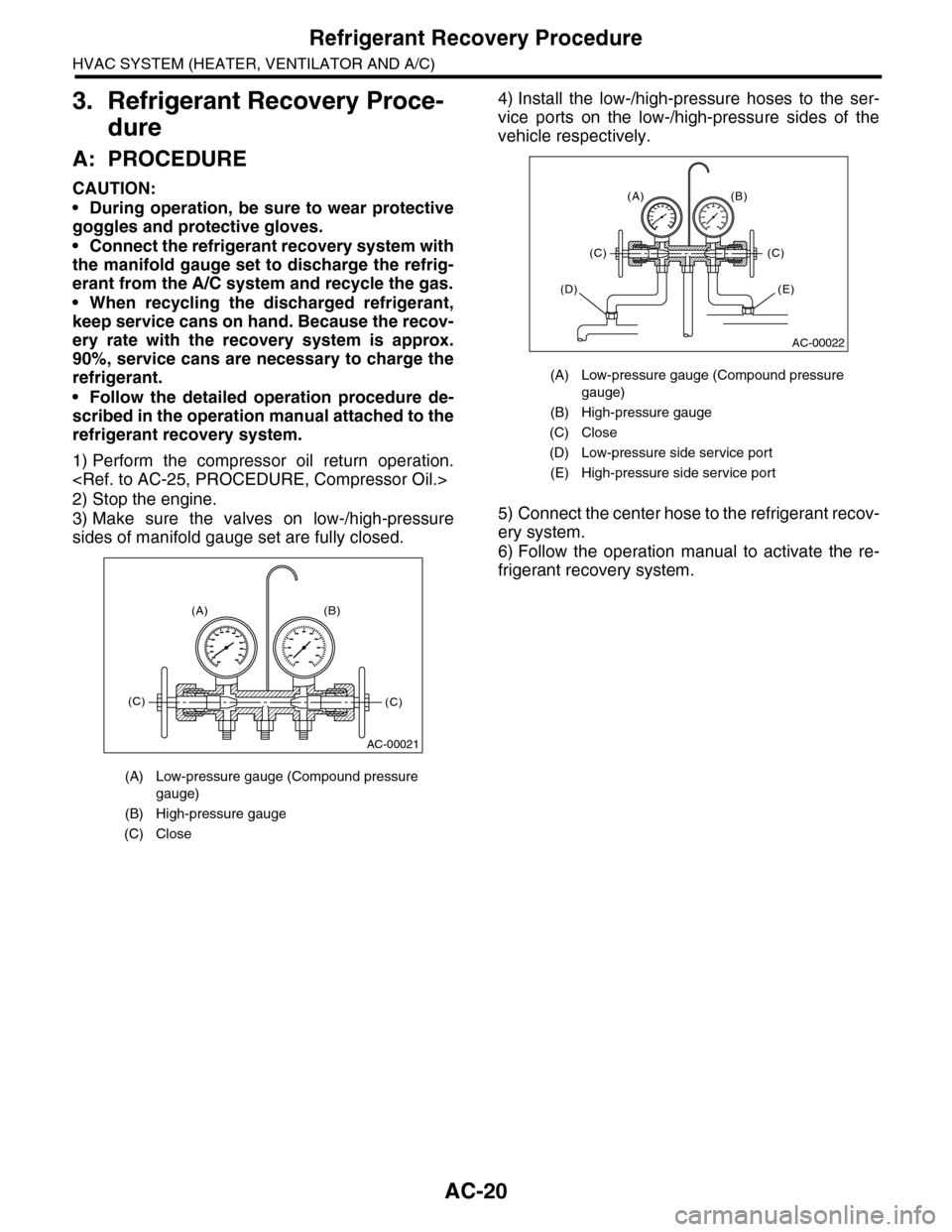
3) Make sure the valves on low-/high-pressure
sides of manifold gauge set are fully closed.
4) Install the low-/high-pressure hoses to the ser-
vice ports on the low-/high-pressure sides of the
vehicle respectively.
5) Connect the center hose to the refrigerant recov-
ery system.
6) Follow the operation manual to activate the re-
frigerant recovery system.
(A) Low-pressure gauge (Compound pressure
gauge)
(B) High-pressure gauge
(C) Close
AC-00021
(A) (B)
(C)(C)
(A) Low-pressure gauge (Compound pressure
gauge)
(B) High-pressure gauge
(C) Close
(D) Low-pressure side service port
(E) High-pressure side service port
AC-00022
(A) (B)
(C)(C)
(E)(D)
Page 347 of 2453

AC-21
Refrigerant Charging Procedure
HVAC SYSTEM (HEATER, VENTILATOR AND A/C)
4. Refrigerant Charging Proce-
dure
A: PROCEDURE
CAUTION:
•During operation, be sure to wear protective
goggles and protective gloves.
•Before charging the refrigerant, evacuate the
system to remove small amounts of moisture
remaining in the system.
The moisture in the system can be completely
evacuated only under the minimum vacuum
level. The minimum vacuum level affects the
temperature in the system.
•The list below shows the vacuum values nec-
essary to boil water at various temperatures. In
addition, the vacuum levels indicated on the
gauge are approx. 3.3 kPa (25 mmHg, 0.98 inHg)
lower than those measured at 304.8 m (1,000 ft)
above sea level.
1) Close the valves on low-/high-pressure sides of
the manifold gauge.
2) Install the low-/high-pressure hoses to the corre-
sponding service ports on the vehicle.
3) Connect the center hose of the manifold gauge
set with the vacuum pump.
4) Carefully open the valves on the low-/high-pres-
sure sides to activate the vacuum pump.
5) After the low-pressure gauge reaches 100.0 kPa
(750 mmHg, 29.5 inHg) or higher, evacuate the
system for approx. 15 minutes. (Continue evacua-
tion).
6) After 15 minutes of evacuation, if the reading
shows 100.0 kPa (750 mmHg, 29.5 inHg) or higher,
close the valves on the both sides to stop the vac-
uum pump.
Va c u u m l eve l r e q u i r e d t o b o i l w a t e r ( a t s e a l eve l )
Te m p e r a t u r e Va c u u m
1.7°C (35°F) 100.9 kPa (757 mmHg, 29.8 inHg)
7.2°C (45°F) 100.5 kPa (754 mmHg, 29.7 inHg)
12.8°C (55°F) 99.8 kPa (749 mmHg, 29.5 inHg)
18.3°C (65°F) 99.2 kPa (744 mmHg, 29.3 inHg)
23.9°C (75°F) 98.5 kPa (739 mmHg, 29.1 inHg)
29.4°C (85°F) 97.2 kPa (729 mmHg, 28.7 inHg)
35°C (95°F) 95.8 kPa (719 mmHg, 28.3 inHg)
(A) Low-pressure gauge (Compound pressure
gauge)
(B) High-pressure gauge
(C) Close
AC-00023
(A) (B)
(C)(C)
(A) Low-pressure gauge (Compound pressure
gauge)
(B) High-pressure gauge
(C) Slowly open
(D) Vacuum pump turn on
(A) Low-pressure gauge (Compound pressure
gauge)
(B) High-pressure gauge
(C) Close
(D) Vacuum pump turn off
AC-00024
(A) (B)
(D)
(C)(C)
AC-00025
AC-00026
(A) (B)
(D)
(C)(C)
Page 348 of 2453

AC-22
Refrigerant Charging Procedure
HVAC SYSTEM (HEATER, VENTILATOR AND A/C)
7) Note the low-pressure gauge reading.
8) Leave it at least 5 minutes, and then check the
low-pressure gauge reading for any changes.
If the gauge indicator shows near zero point, it is a
sign of leakage. Check pipe connector points, re-
pair them, and make sure there is no leakage.
9) Follow the can tap operation manual, install to
the refrigerant can.
10) Disconnect the center manifold hose from the
vacuum pump, and connect the hose to the tap
valve.
11) When a 13.6 kg (30 lb) refrigerant container is
used, measure the weight of the refrigerant amount
to use using a scale.
12) Confirm that all the 3 hoses are connected se-
curely to the manifold gauge set.
13) Open the valve on the HFC-134a source.
14) Loosen the center hose connection on the
manifold gauge set (if applicable, press a purge
valve on the manifold gauge set) for a few seconds
to allow the air in the center hose to escape by the
refrigerant pressure.
15) Stop the engine and carefully open the high-
pressure valve.
CAUTION:
Do not open the low-pressure valve.
CAUTION:
Never run the engine while charging from the
high-pressure side.
16) Close the high-pressure valve when the low-
pressure gauge reaches 98 kPa (1 kg/cm2, 14 psi).
Using a leak tester, check the system for leaks.
If any leakage is found after the refrigerant recov-
ery is completed, repair the applicable area.
(A) Tap valve
(B) Center manifold hose
(A) Refrigerant container (HFC-134a)
(B) Scale
AC-00027
AC-00028
(A)
(B)
AC-00029
(A)
(B)
(A) Low-pressure gauge (Compound pressure
gauge)
(B) High-pressure gauge
(C) Close
(A) Low-pressure gauge (Compound pressure
gauge)
(B) High-pressure gauge
(C) Close
(D) Ignition switch OFF
(E) Slowly open
AC-00030
(A) (B)
(C)(C)
AC-00031
(A) (B)
(E)
(D)
(C)
Page 367 of 2453

AC-41
Pressure Switch (Triple Pressure Switch)
HVAC SYSTEM (HEATER, VENTILATOR AND A/C)
20.Pressure Switch (Triple Pres-
sure Switch)
A: INSPECTION
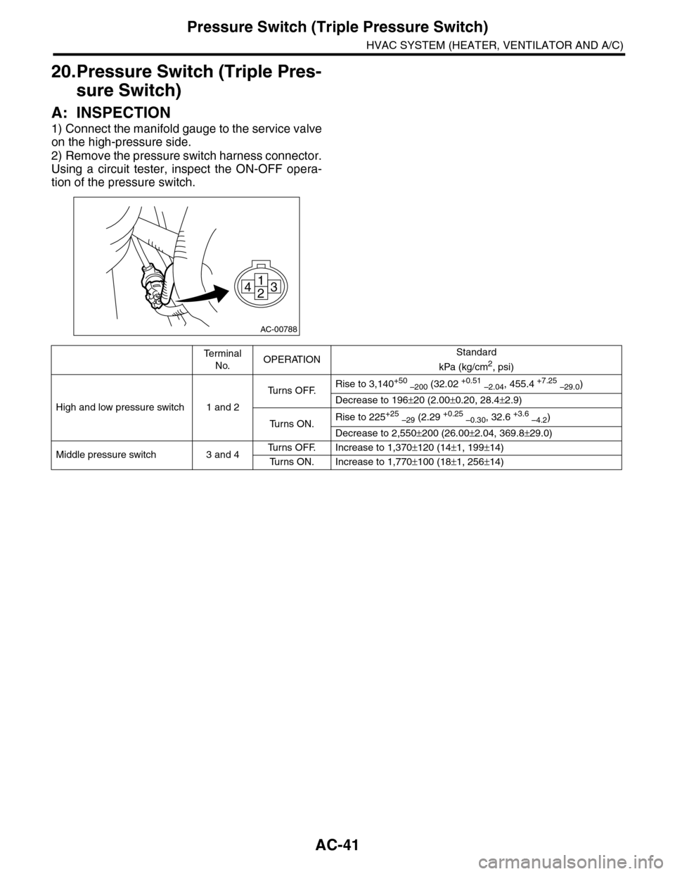
1) Connect the manifold gauge to the service valve
on the high-pressure side.
2) Remove the pressure switch harness connector.
Using a circuit tester, inspect the ON-OFF opera-
tion of the pressure switch.
AC-00788
1
243
Te r m i n a l
No.OPERATIONStandard
kPa (kg/cm2, psi)
High and low pressure switch 1 and 2
Tu r n s O F F.Rise to 3,140+50 –200 (32.02 +0.51 –2.04, 455.4 +7.25 –29.0)
Decrease to 196±20 (2.00±0.20, 28.4±2.9)
Tu r n s O N .Rise to 225+25 –29 (2.29 +0.25 –0.30, 32.6 +3.6 –4.2)
Decrease to 2,550±200 (26.00±2.04, 369.8±29.0)
Middle pressure switch 3 and 4Tu r n s O F F. I n c r e a s e t o 1 , 3 7 0±120 (14±1, 199±14)
Tu r n s O N . I n c r e a s e t o 1 , 7 7 0±100 (18±1, 256±14)
Page 933 of 2453

PS-53
General Diagnostic Table
POWER ASSISTED SYSTEM (POWER STEERING)
3. INSPECTION OF CLEARANCE
This table lists various clearances that must be correctly adjusted to ensure the normal vehicle driving with-
out interfering noise, or any other faults.
Install locations Minimum allowance mm (in)
(1) Crossmember-to-Hose assembly 10 (0.39)
(2) Front frame side-to-Hose assembly 15 (0.59)
(3) Air bag sensor to cooler pipe assembly 10 (0.39)
(4) Air cleaner case-to-Suction hose 10 (0.39)
(5) VDCH/U to Reservoir tank bracket 10 (0.39)
(6) Air boots to Hose clip15 (0.59)
(7) Air boot-to-Hose assembly15 (0.59)
(8) Protector to Hose assembly10 (0.39)
(9) Intake manifold to Suction hose 10 (0.39)
(10) Intake manifold to hose assembly 10 (0.39)
(11) Air cleaner case to Cooler pipe joint block 5 (0.20)
(12) Chain cover to Cooler pipe joint block 20 (0.79)
(13) Oil pipe to Cooler pipe joint block 20 (0.79)
(14) Suction hose to Hose assembly 10 (0.39)
(15) Air boot to Reservoir tank10 (0.39)
(16) Brake pipe to Reservoir tank10 (0.39)
(17) Harness to Hose assembly10 (0.39)
(18) Relay box to Hose assembly15 (0.59)
(19) Bumper beam to Cooler pipe assembly 10 (0.39)
(20) Radiator bracket to Cooler pipe assembly 10 (0.39)
(21) ATF cooler to Cooler pipe assembly 10 (0.39)
(22) Undercover to cooler pipe assembly 10 (0.39)
(23) Protector to Hose assembly10 (0.39)
(24) Protector to Hose assembly15 (0.59)
(25) Return hose to Hose assembly 10 (0.39)
(26) Air cleaner case to Hose assembly 10 (0.39)
(27) Suction hose to Hose assembly 10 (0.39)
(28) Air cleaner case to Return hose 3 (0.12)
(29) Valve housing to DOJ12 (0.47)
(30) Valve housing to Crossmember 1 (0.04)
(31) Mount to Crossmember There must be no contact.
(32) Feed tube to Crossmember3 (0.12)
(33) Elbow to Crossmember3 (0.12)
(34) Cylinder pipe to Crossmember 3 (0.12)
(35) Feed tube to Exhaust pipe18 (0.71)
(36) Tie-rod end to Brake dust cover 2.5 (0.10)
(37) Coupling rubber to AT level gage 10 (0.39)
(38) Yoke to Brake booster5 (0.20)