2009 SUBARU TRIBECA Manifold
[x] Cancel search: ManifoldPage 1951 of 2453
ME(H6DO)-85
Engine Trouble in General
MECHANICAL
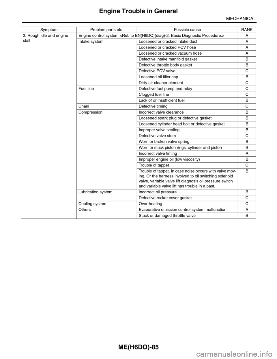
2. Rough idle and engine
stall
Engine control system
Intake system Loosened or cracked intake duct A
Loosened or cracked PCV hose A
Loosened or cracked vacuum hose A
Defective intake manifold gasket B
Defective throttle body gasket B
Defective PCV valve C
Loosened oil filler cap B
Dirty air cleaner element C
Fuel line Defective fuel pump and relay C
Clogged fuel line C
Lack of or insufficient fuel B
Chain Defective timing C
Compression Incorrect valve clearance B
Loosened spark plug or defective gasket B
Loosened cylinder head bolt or defective gasket B
Improper valve sealing B
Defective valve stem C
Wor n or broken valve spr ing B
Wor n or stuck piston r ings, cylinder and piston B
Incorrect valve timing A
Improper engine oil (low viscosity) B
Tr o u b l e o f t a p p e t C
Tr o u b l e o f t a p p e t . I n c a s e n o i s e o c c u r s w i t h v a l v e m o v -
ing. Or the harness involved to oil switching solenoid
valve, variable valve lift diagnosis oil pressure switch
and variable valve lift has trouble in a past.
B
Lubrication system Incorrect oil pressure B
Defective rocker cover gasket C
Cooling system Over-heating C
Others Evaporative emission control system malfunction A
Stuck or damaged throttle valve B
Symptom Problem parts etc. Possible cause RANK
Page 1952 of 2453
ME(H6DO)-86
Engine Trouble in General
MECHANICAL
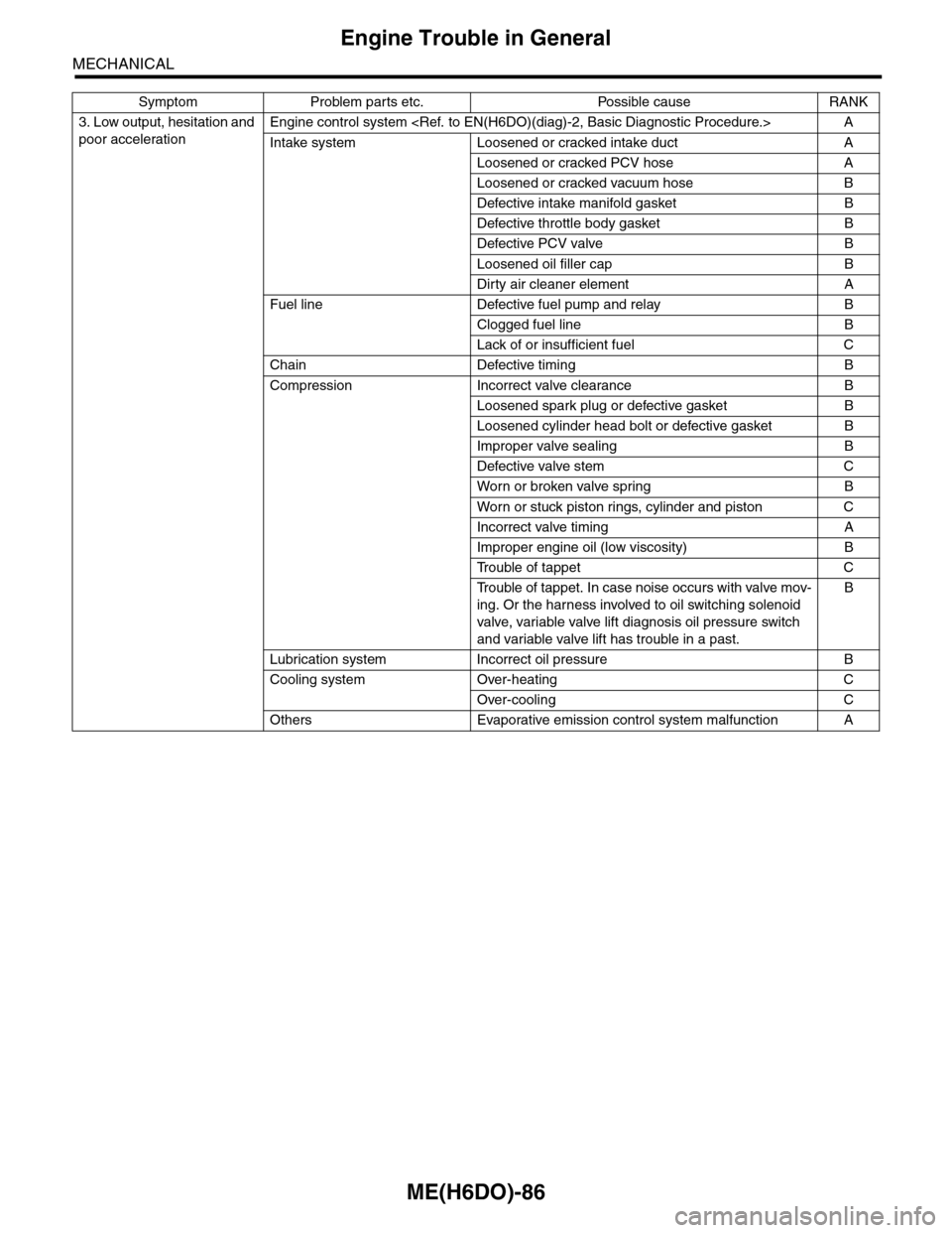
3. Low output, hesitation and
poor acceleration
Engine control system
Intake system Loosened or cracked intake duct A
Loosened or cracked PCV hose A
Loosened or cracked vacuum hose B
Defective intake manifold gasket B
Defective throttle body gasket B
Defective PCV valve B
Loosened oil filler cap B
Dirty air cleaner element A
Fuel line Defective fuel pump and relay B
Clogged fuel line B
Lack of or insufficient fuel C
Chain Defective timing B
Compression Incorrect valve clearance B
Loosened spark plug or defective gasket B
Loosened cylinder head bolt or defective gasket B
Improper valve sealing B
Defective valve stem C
Wor n or broken valve spr ing B
Wor n or stuck piston r ings, cylinder and piston C
Incorrect valve timing A
Improper engine oil (low viscosity) B
Tr o u b l e o f t a p p e t C
Tr o u b l e o f t a p p e t . I n c a s e n o i s e o c c u r s w i t h v a l v e m o v -
ing. Or the harness involved to oil switching solenoid
valve, variable valve lift diagnosis oil pressure switch
and variable valve lift has trouble in a past.
B
Lubrication system Incorrect oil pressure B
Cooling system Over-heating C
Over-cooling C
Others Evaporative emission control system malfunction A
Symptom Problem parts etc. Possible cause RANK
Page 1953 of 2453
ME(H6DO)-87
Engine Trouble in General
MECHANICAL
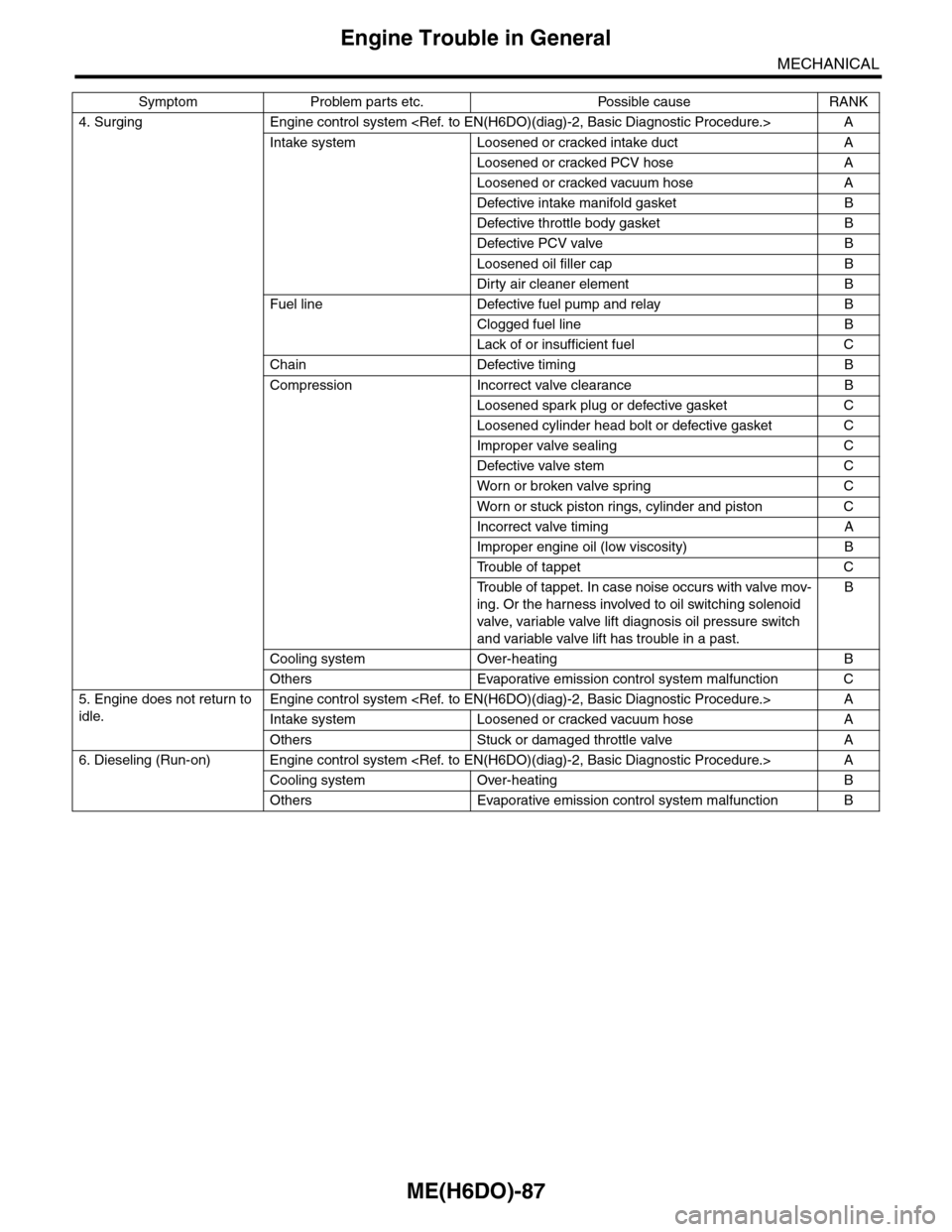
4. Surging Engine control system
Intake system Loosened or cracked intake duct A
Loosened or cracked PCV hose A
Loosened or cracked vacuum hose A
Defective intake manifold gasket B
Defective throttle body gasket B
Defective PCV valve B
Loosened oil filler cap B
Dirty air cleaner element B
Fuel line Defective fuel pump and relay B
Clogged fuel line B
Lack of or insufficient fuel C
Chain Defective timing B
Compression Incorrect valve clearance B
Loosened spark plug or defective gasket C
Loosened cylinder head bolt or defective gasket C
Improper valve sealing C
Defective valve stem C
Wor n or broken valve spr ing C
Wor n or stuck piston r ings, cylinder and piston C
Incorrect valve timing A
Improper engine oil (low viscosity) B
Tr o u b l e o f t a p p e t C
Tr o u b l e o f t a p p e t . I n c a s e n o i s e o c c u r s w i t h v a l v e m o v -
ing. Or the harness involved to oil switching solenoid
valve, variable valve lift diagnosis oil pressure switch
and variable valve lift has trouble in a past.
B
Cooling system Over-heating B
Others Evaporative emission control system malfunction C
5. Engine does not return to
idle.
Engine control system
Intake system Loosened or cracked vacuum hose A
Others Stuck or damaged throttle valve A
6. Dieseling (Run-on) Engine control system
Cooling system Over-heating B
Others Evaporative emission control system malfunction B
Symptom Problem parts etc. Possible cause RANK
Page 1956 of 2453
ME(H6DO)-90
Engine Noise
MECHANICAL
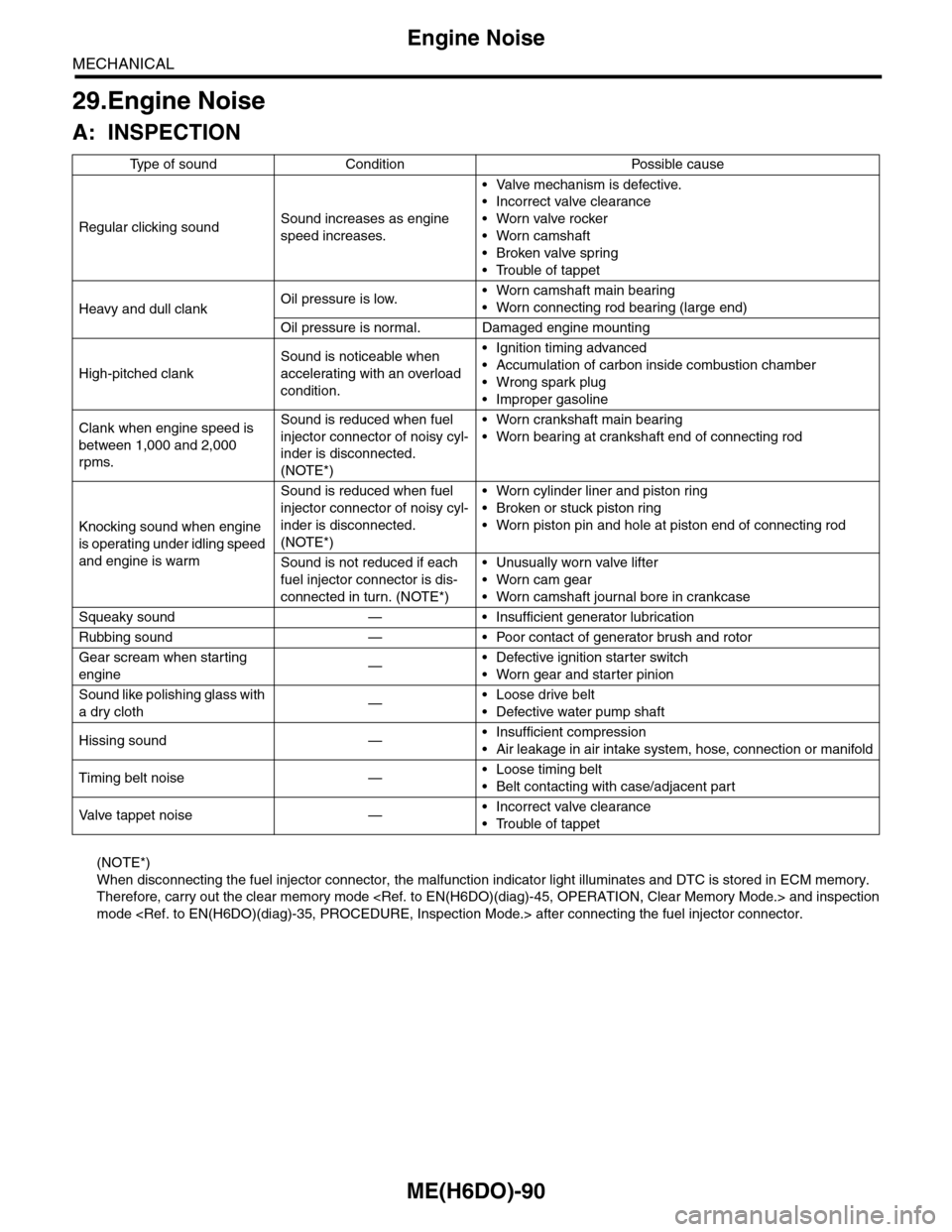
29.Engine Noise
A: INSPECTION
(NOTE*)
When disconnecting the fuel injector connector, the malfunction indicator light illuminates and DTC is stored in ECM memory.
Therefore, carry out the clear memory mode
mode
Ty p e o f s o u n d C o n d i t i o n P o s s i b l e c a u s e
Regular clicking soundSound increases as engine
speed increases.
•Valve mechanism is defective.
•Incorrect valve clearance
•Worn valve rocker
•Worn camshaft
•Broken valve spring
•Trouble of tappet
Heavy and dull clankOil pressure is low.•Worn camshaft main bearing
•Worn connecting rod bearing (large end)
Oil pressure is normal. Damaged engine mounting
High-pitched clank
Sound is noticeable when
accelerating with an overload
condition.
•Ignition timing advanced
•Accumulation of carbon inside combustion chamber
•Wrong spark plug
•Improper gasoline
Clank when engine speed is
between 1,000 and 2,000
rpms.
Sound is reduced when fuel
injector connector of noisy cyl-
inder is disconnected.
(NOTE*)
•Worn crankshaft main bearing
•Worn bearing at crankshaft end of connecting rod
Knocking sound when engine
is operating under idling speed
and engine is warm
Sound is reduced when fuel
injector connector of noisy cyl-
inder is disconnected.
(NOTE*)
•Worn cylinder liner and piston ring
•Broken or stuck piston ring
•Worn piston pin and hole at piston end of connecting rod
Sound is not reduced if each
fuel injector connector is dis-
connected in turn. (NOTE*)
•Unusually worn valve lifter
•Worn cam gear
•Worn camshaft journal bore in crankcase
Squeaky sound — • Insufficient generator lubrication
Rubbing sound — • Poor contact of generator brush and rotor
Gear scream when starting
engine—•Defective ignition starter switch
•Worn gear and starter pinion
Sound like polishing glass with
a dry cloth—•Loose drive belt
•Defective water pump shaft
Hissing sound —•Insufficient compression
•Air leakage in air intake system, hose, connection or manifold
Timing belt noise —•Loose timing belt
•Belt contacting with case/adjacent part
Va l ve t a p p e t n o i s e —•Incorrect valve clearance
•Trouble of tappet
Page 2056 of 2453
5AT-40
Automatic Transmission Assembly
AUTOMATIC TRANSMISSION
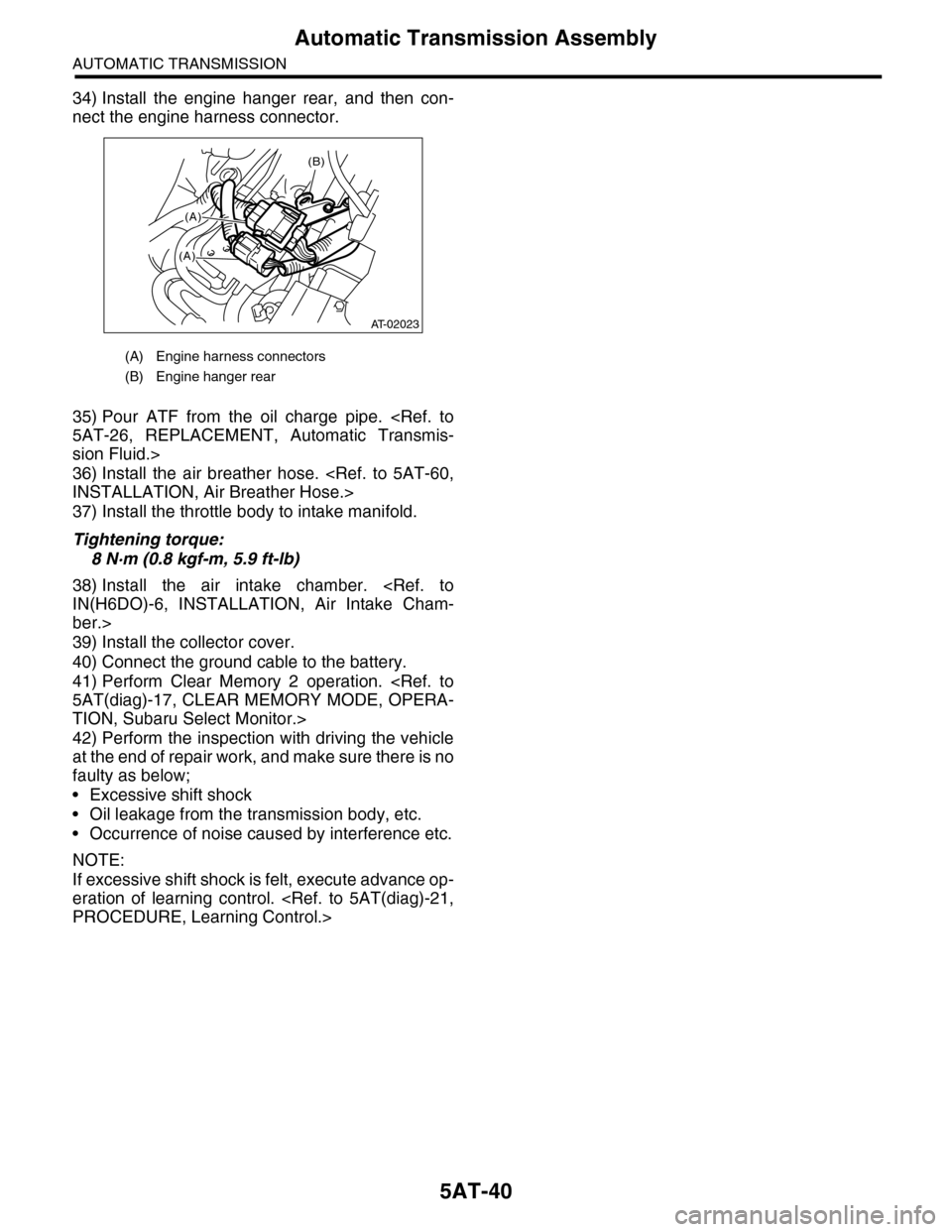
34) Install the engine hanger rear, and then con-
nect the engine harness connector.
35) Pour ATF from the oil charge pipe.
sion Fluid.>
36) Install the air breather hose.
37) Install the throttle body to intake manifold.
Tightening torque:
8 N·m (0.8 kgf-m, 5.9 ft-lb)
38) Install the air intake chamber.
ber.>
39) Install the collector cover.
40) Connect the ground cable to the battery.
41) Perform Clear Memory 2 operation.
TION, Subaru Select Monitor.>
42) Perform the inspection with driving the vehicle
at the end of repair work, and make sure there is no
faulty as below;
•Excessive shift shock
•Oil leakage from the transmission body, etc.
•Occurrence of noise caused by interference etc.
NOTE:
If excessive shift shock is felt, execute advance op-
eration of learning control.
(A) Engine harness connectors
(B) Engine hanger rear
(B)
(A)
(A)
AT-02023
Page 2317 of 2453
WI-33
Engine Electrical System
WIRING SYSTEM
WI-08040
A3D2
D22D23
POWERCIRCUIT
COMBINATION METER
C16B27D18D19D20D21
C11C22
C6
B23B29B31B21
1
2
3
4
5
6
ACCELERATORPEDAL POSITIONSENSOR
JOINT CONNECTOR A
JOINT CONNECTOR
MALFUNCTION INDICATOR LIGHTOIL PRESSUREWARNING LIGHT
I/F
I/F
I/F
VDC CONTROL MODULE
IGNITION COIL NO.1
BODY INTEGRATED UNIT(CAN COMMUNICATION LINE)
OILPRESSURESWITCH
CRANKSHAFT POSITION SENSORA13A14
ENGINE GROUND
ECM
A18A28
D4D5
A19B22A6A29A34
D15B30
D14D17D16D31D30
ELECTRONIC THROTTLE CONTROL
A24
A25A16
A15
A32
D1
MANIFOLD ABSOLUTE PRESSURE SENSOR
ENGINE COOLANT TEMPRERATURE SENSOR
VVL DIAGNOSIS OIL PRESSURE SWITCH RH
D25D24
KNOCK SENSOR 2
D6D26D7
A5
MICRO COMPUTER
CAN TRANSCEIVER &RECEIVER
OIL SWITCHING SOLENOID VALVE RH
TA C H O -METER
SPEEDMETER
ENGINECOOLANTTEM-PERATUREGAUGE
DATA LINK CONNECTOR
TEST MODECONNECTOR
OIL TEMPERATURE SENSORA23
A31D3
VVL DIAGNOSIS OIL PRESSURE SWITCH LH
KNOCK SENSOR 1
OIL SWITCHING SOLENOID VALVE LH
INTAKE OIL FLOW CONTROL SOLENOID VALVE RH
INTAKE OIL FLOW CONTROL SOLENOID VALVE LH
IGNITION COIL NO.2 IGNITION COIL NO.3 IGNITION COIL NO.4 IGNITION COIL NO.5 IGNITION COIL NO.6
789
Page 2327 of 2453
WI-43
Engine Electrical System
WIRING SYSTEM
WI-08050
E/G-10E/G-10
D:B137
D29
RG
A6
YW
31E28
E76
E77
A19
LY
YWYGE4
B:B135A:B134ECM
CPCSOLENOID
E2
B21
A33
PB
LYYW
LYYW
21
15
RGYL
(BLUE)E4
12
B21
12345678910 1112 13 14 15 16 17 18 19 20 21 2223 24 25 26 27 28 29 30 31 32 33
34 3542 4336 3738 39
48 4950 5152 5354
40 41444546 47
YG
YG
B30
YG
LGYG
YGV
B424
JPINTCONNECTORE/G-07M
B424
34561278
D: B137
85610 11 12 13 14 157213416
3019 20 2228 29
91718 2521 23 243126 27
E/G-12V
YG
YG
6
E/G-09R
LY
2
RG
RG
2
YL
YL
3
E/G-07L
E/G-06I
E/G-06J
E/G-01A
POWER STEERING OILPRESSURE SWITCH
E19PB
9
PB
PB
E/G-09S
E/G-09T
41
RG
RG
197
PYW
YGYW
20
LY
LY
A29
P
INTAKE MANIFOLDPRESSURE SENSOR
E28
123
(BLACK)(BLACK)E77
134562
(DARK GRAY)
A:B134
85610 11 12 13 14 157213416
3019 20 2228 29
91718252123 24323126 2733 34
*1
*1
*1
*1
*1*1
*1 : TERMINAL NO. OPTIONAL ARRANGEMENT
B:B135
5672134
29
101112131415252416
30
98171819202821222332312627333435
Page 2441 of 2453
WI-157
Engine Wiring Harness and Transmission Cord
WIRING SYSTEM
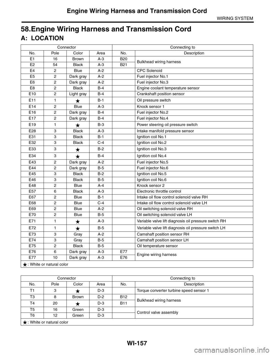
58.Engine Wiring Harness and Transmission Cord
A: LOCATION
Connector Connecting to
No. Pole Color Area No. Description
E1 16 Brown A-3 B20Bulkhead wiring harnessE2 54 Black A-3 B21
E4 2 Blue A-2 CPC Solenoid
E5 2 Dark gray A-2 Fuel injector No.1
E6 2 Dark gray A-2 Fuel injector No.3
E8 2 Black B-4 Engine coolant temperature sensor
E10 2 Light gray B-4 Crankshaft position sensor
E11 1 B-1 Oil pressure switch
E14 2 Blue A-3 Knock sensor 1
E16 2 Dark gray B-4 Fuel injector No.2
E17 2 Dark gray B-4 Fuel injector No.4
E19 1 B-3 Power steering oil pressure switch
E28 3 Black A-3 Intake manifold pressure sensor
E31 3 Black B-1 Ignition coil No.1
E32 3 Black C-4 Ignition coil No.2
E33 3 B-2 Ignition coil No.3
E34 3 B-4 Ignition coil No.4
E43 2 Dark gray A-2 Fuel injector No.5
E44 2 Dark gray B-5 Fuel injector No.6
E45 3 Black B-2 Ignition coil No.5
E46 3 Black B-5 Ignition coil No.6
E48 2 Blue A-4 Knock sensor 2
E57 6 Black A-3 Electronic throttle control
E67 2 Blue B-1 Intake oil flow control solenoid valve RH
E68 2 Blue C-4 Intake oil flow control solenoid valve LH
E69 2 Blue A-2 Oil switching solenoid valve RH
E70 2 Blue B-5 Oil switching solenoid valve LH
E71 1 A-3 Variable valve lift diagnosis oil pressure switch RH
E72 1 B-5 Variable valve lift diagnosis oil pressure switch LH
E73 3 Gray A-2 Camshaft position sensor RH
E74 3 Gray B-5 Camshaft position sensor LH
E75 2 Black B-5 Oil temperature sensor
E76 6 Dark gray A-3 E77Engine wiring harnessE77 10 Dark gray A-3 E76
: White or natural color
Connector Connecting to
No. Pole Color Area No. Description
T1 3 D-3 Torque converter turbine speed sensor 1
T3 8 Brown D-2 B12Bulkhead wiring harnessT4 20 D-3 B11
T5 16 Green D-3Control valve assemblyT6 12 Green D-3
: White or natural color