2009 SUBARU TRIBECA Manifold
[x] Cancel search: ManifoldPage 1196 of 2453
EN(H6DO)(diag)-35
Inspection Mode
ENGINE (DIAGNOSTICS)
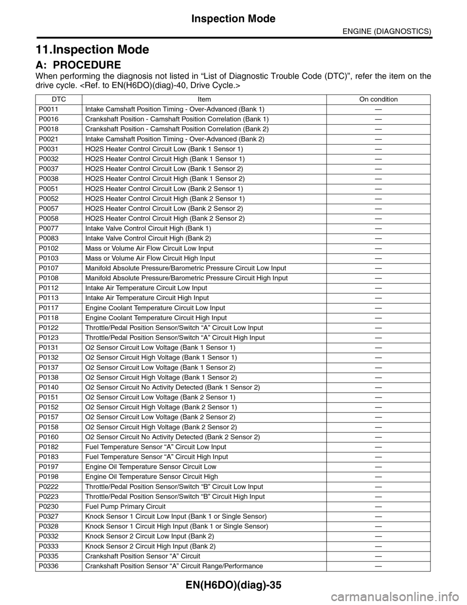
11.Inspection Mode
A: PROCEDURE
When performing the diagnosis not listed in “List of Diagnostic Trouble Code (DTC)”, refer the item on the
drive cycle.
DTC Item On condition
P0011 Intake Camshaft Position Timing - Over-Advanced (Bank 1) —
P0016 Crankshaft Position - Camshaft Position Correlation (Bank 1) —
P0018 Crankshaft Position - Camshaft Position Correlation (Bank 2) —
P0021 Intake Camshaft Position Timing - Over-Advanced (Bank 2) —
P0031 HO2S Heater Control Circuit Low (Bank 1 Sensor 1) —
P0032 HO2S Heater Control Circuit High (Bank 1 Sensor 1) —
P0037 HO2S Heater Control Circuit Low (Bank 1 Sensor 2) —
P0038 HO2S Heater Control Circuit High (Bank 1 Sensor 2) —
P0051 HO2S Heater Control Circuit Low (Bank 2 Sensor 1) —
P0052 HO2S Heater Control Circuit High (Bank 2 Sensor 1) —
P0057 HO2S Heater Control Circuit Low (Bank 2 Sensor 2) —
P0058 HO2S Heater Control Circuit High (Bank 2 Sensor 2) —
P0077 Intake Valve Control Circuit High (Bank 1) —
P0083 Intake Valve Control Circuit High (Bank 2) —
P0102 Mass or Volume Air Flow Circuit Low Input —
P0103 Mass or Volume Air Flow Circuit High Input —
P0107 Manifold Absolute Pressure/Barometric Pressure Circuit Low Input —
P0108 Manifold Absolute Pressure/Barometric Pressure Circuit High Input —
P0112 Intake Air Temperature Circuit Low Input —
P0113 Intake Air Temperature Circuit High Input —
P0117 Engine Coolant Temperature Circuit Low Input —
P0118 Engine Coolant Temperature Circuit High Input —
P0122 Throttle/Pedal Position Sensor/Switch “A” Circuit Low Input —
P0123 Throttle/Pedal Position Sensor/Switch “A” Circuit High Input —
P0131 O2 Sensor Circuit Low Voltage (Bank 1 Sensor 1) —
P0132 O2 Sensor Circuit High Voltage (Bank 1 Sensor 1) —
P0137 O2 Sensor Circuit Low Voltage (Bank 1 Sensor 2) —
P0138 O2 Sensor Circuit High Voltage (Bank 1 Sensor 2) —
P0140 O2 Sensor Circuit No Activity Detected (Bank 1 Sensor 2) —
P0151 O2 Sensor Circuit Low Voltage (Bank 2 Sensor 1) —
P0152 O2 Sensor Circuit High Voltage (Bank 2 Sensor 1) —
P0157 O2 Sensor Circuit Low Voltage (Bank 2 Sensor 2) —
P0158 O2 Sensor Circuit High Voltage (Bank 2 Sensor 2) —
P0160 O2 Sensor Circuit No Activity Detected (Bank 2 Sensor 2) —
P0182 Fuel Temperature Sensor “A” Circuit Low Input —
P0183 Fuel Temperature Sensor “A” Circuit High Input —
P0197 Engine Oil Temperature Sensor Circuit Low —
P0198 Engine Oil Temperature Sensor Circuit High —
P0222 Throttle/Pedal Position Sensor/Switch “B” Circuit Low Input —
P0223 Throttle/Pedal Position Sensor/Switch “B” Circuit High Input —
P0230 Fuel Pump Primary Circuit —
P0327 Knock Sensor 1 Circuit Low Input (Bank 1 or Single Sensor) —
P0328 Knock Sensor 1 Circuit High Input (Bank 1 or Single Sensor) —
P0332 Knock Sensor 2 Circuit Low Input (Bank 2) —
P0333 Knock Sensor 2 Circuit High Input (Bank 2) —
P0335 Crankshaft Position Sensor “A” Circuit —
P0336 Crankshaft Position Sensor “A” Circuit Range/Performance —
Page 1231 of 2453
EN(H6DO)(diag)-70
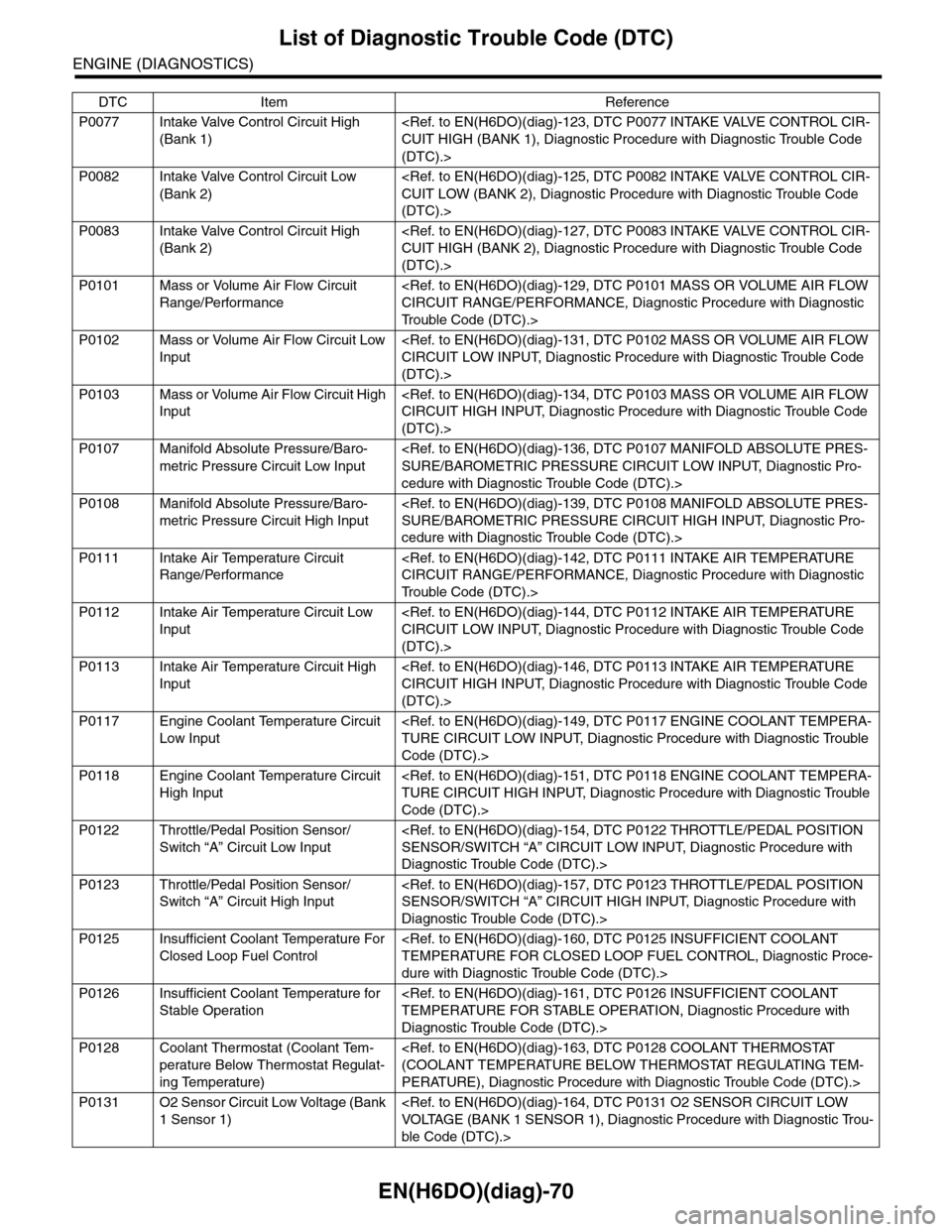
List of Diagnostic Trouble Code (DTC)
ENGINE (DIAGNOSTICS)
P0077 Intake Valve Control Circuit High
(Bank 1)
(DTC).>
P0082 Intake Valve Control Circuit Low
(Bank 2)
(DTC).>
P0083 Intake Valve Control Circuit High
(Bank 2)
(DTC).>
P0101 Mass or Volume Air Flow Circuit
Range/Performance
Tr o u b l e C o d e ( D T C ) . >
P0102 Mass or Volume Air Flow Circuit Low
Input
(DTC).>
P0103 Mass or Volume Air Flow Circuit High
Input
(DTC).>
P0107 Manifold Absolute Pressure/Baro-
metric Pressure Circuit Low Input
cedure with Diagnostic Trouble Code (DTC).>
P0108 Manifold Absolute Pressure/Baro-
metric Pressure Circuit High Input
cedure with Diagnostic Trouble Code (DTC).>
P0111 Intake Air Temperature Circuit
Range/Performance
Tr o u b l e C o d e ( D T C ) . >
P0112 Intake Air Temperature Circuit Low
Input
(DTC).>
P0113 Intake Air Temperature Circuit High
Input
(DTC).>
P0117 Engine Coolant Temperature Circuit
Low Input
Code (DTC).>
P0118 Engine Coolant Temperature Circuit
High Input
Code (DTC).>
P0122 Throttle/Pedal Position Sensor/
Switch “A” Circuit Low Input
Diagnostic Trouble Code (DTC).>
P0123 Throttle/Pedal Position Sensor/
Switch “A” Circuit High Input
Diagnostic Trouble Code (DTC).>
P0125 Insufficient Coolant Temperature For
Closed Loop Fuel Control
dure with Diagnostic Trouble Code (DTC).>
P0126 Insufficient Coolant Temperature for
Stable Operation
Diagnostic Trouble Code (DTC).>
P0128 Coolant Thermostat (Coolant Tem-
perature Below Thermostat Regulat-
ing Temperature)
PERATURE), Diagnostic Procedure with Diagnostic Trouble Code (DTC).>
P0131 O2 Sensor Circuit Low Voltage (Bank
1 Sensor 1)
ble Code (DTC).>
DTC Item Reference
Page 1280 of 2453
EN(H6DO)(diag)-119
Diagnostic Procedure with Diagnostic Trouble Code (DTC)
ENGINE (DIAGNOSTICS)
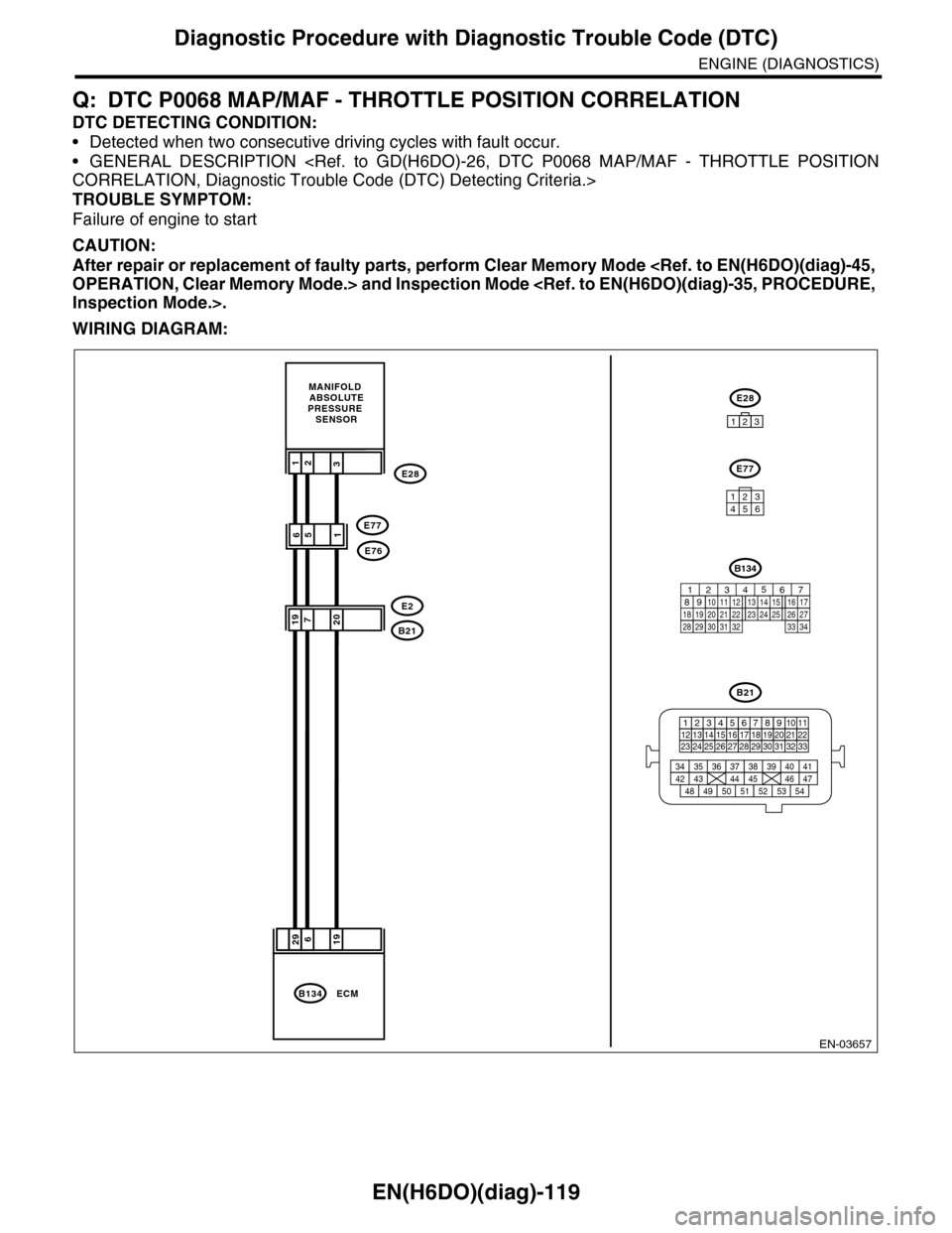
Q: DTC P0068 MAP/MAF - THROTTLE POSITION CORRELATION
DTC DETECTING CONDITION:
•Detected when two consecutive driving cycles with fault occur.
•GENERAL DESCRIPTION
TROUBLE SYMPTOM:
Failure of engine to start
CAUTION:
After repair or replacement of faulty parts, perform Clear Memory Mode
WIRING DIAGRAM:
EN-03657
29619
MANIFOLD ABSOLUTEPRESSURE SENSOR
19207B21
E2
132E28
ECMB134
B21
123412131415567816171819910 1120212223 24 25 2627 28 29 3031 32 33
3534 37363938 41404342 4445 47464948 51505352 54
651E77
E76
E28
123
E77
134562
B134
85610 11 12 13 14 157213416
3019 20 2228 29
91718252123 24323126 2733 34
Page 1281 of 2453
EN(H6DO)(diag)-120
Diagnostic Procedure with Diagnostic Trouble Code (DTC)
ENGINE (DIAGNOSTICS)
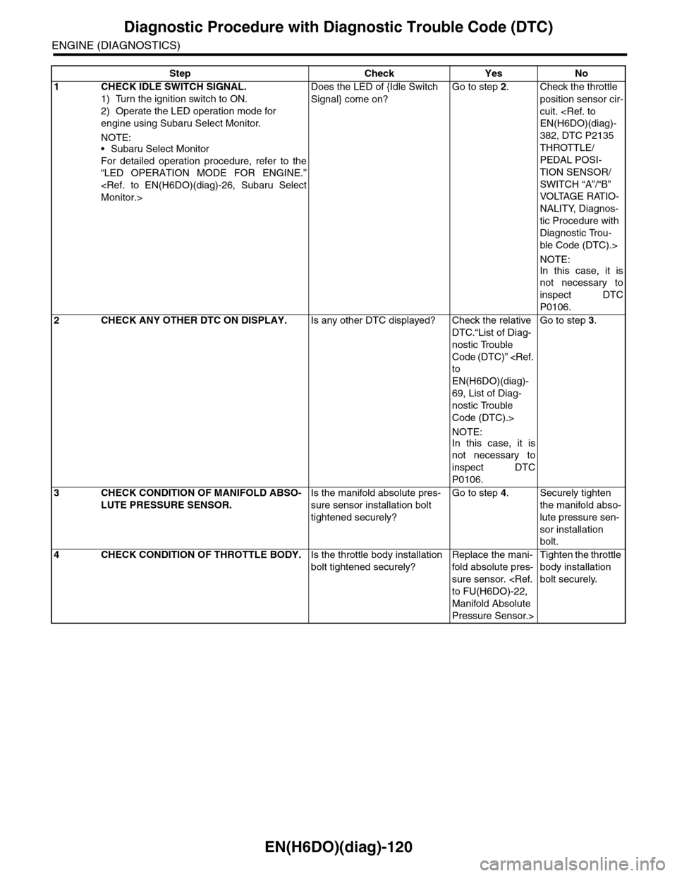
Step Check Yes No
1CHECK IDLE SWITCH SIGNAL.
1) Turn the ignition switch to ON.
2) Operate the LED operation mode for
engine using Subaru Select Monitor.
NOTE:•Subaru Select Monitor
For detailed operation procedure, refer to the
“LED OPERATION MODE FOR ENGINE.”
Does the LED of {Idle Switch
Signal} come on?
Go to step 2.Check the throttle
position sensor cir-
cuit.
382, DTC P2135
THROTTLE/
PEDAL POSI-
TION SENSOR/
SWITCH “A”/“B”
VOLTAGE RATIO-
NALITY, Diagnos-
tic Procedure with
Diagnostic Trou-
ble Code (DTC).>
NOTE:
In this case, it is
not necessary to
inspect DTC
P0106.
2CHECK ANY OTHER DTC ON DISPLAY.Is any other DTC displayed? Check the relative
DTC.“List of Diag-
nostic Trouble
Code (DTC)”
EN(H6DO)(diag)-
69, List of Diag-
nostic Trouble
Code (DTC).>
NOTE:
In this case, it is
not necessary to
inspect DTC
P0106.
Go to step 3.
3CHECK CONDITION OF MANIFOLD ABSO-
LUTE PRESSURE SENSOR.
Is the manifold absolute pres-
sure sensor installation bolt
tightened securely?
Go to step 4.Securely tighten
the manifold abso-
lute pressure sen-
sor installation
bolt.
4CHECK CONDITION OF THROTTLE BODY.Is the throttle body installation
bolt tightened securely?
Replace the mani-
fold absolute pres-
sure sensor.
Manifold Absolute
Pressure Sensor.>
Tighten the throttle
body installation
bolt securely.
Page 1297 of 2453
EN(H6DO)(diag)-136
Diagnostic Procedure with Diagnostic Trouble Code (DTC)
ENGINE (DIAGNOSTICS)
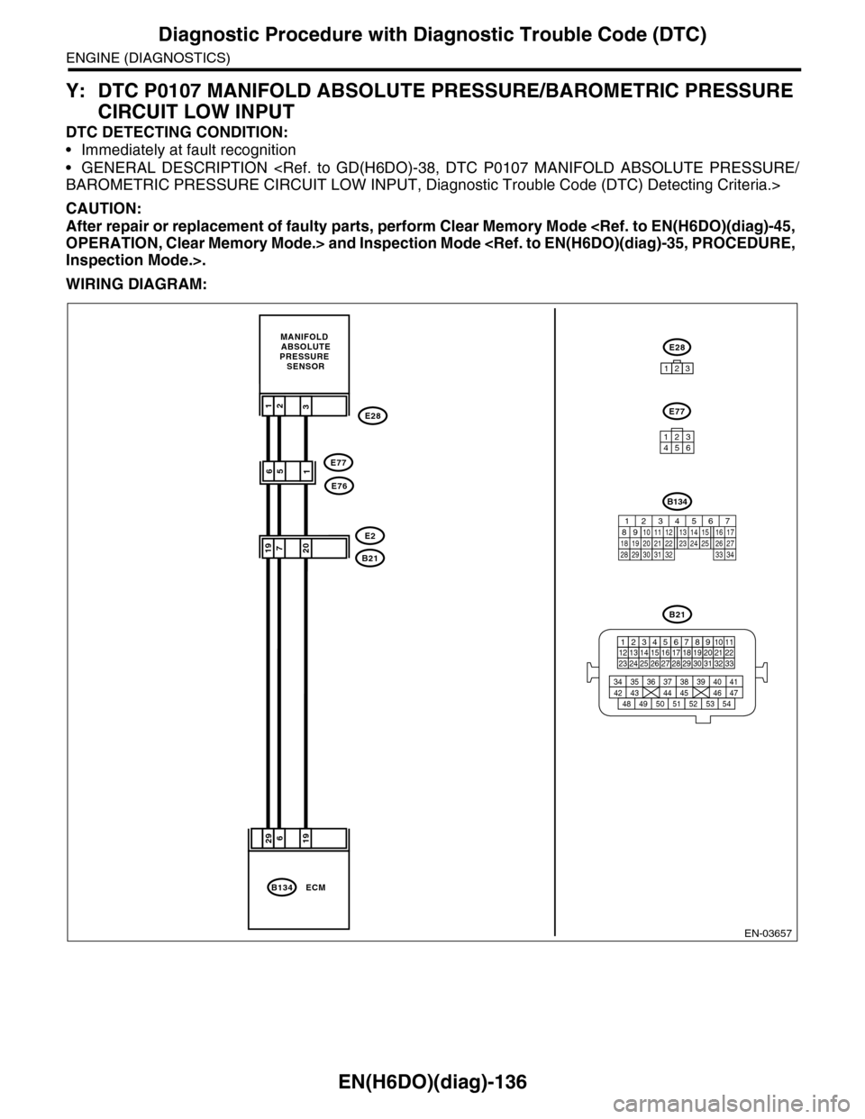
Y: DTC P0107 MANIFOLD ABSOLUTE PRESSURE/BAROMETRIC PRESSURE
CIRCUIT LOW INPUT
DTC DETECTING CONDITION:
•Immediately at fault recognition
•GENERAL DESCRIPTION
CAUTION:
After repair or replacement of faulty parts, perform Clear Memory Mode
WIRING DIAGRAM:
EN-03657
29619
MANIFOLD ABSOLUTEPRESSURE SENSOR
19207B21
E2
132E28
ECMB134
B21
123412131415567816171819910 1120212223 24 25 2627 28 29 3031 32 33
3534 37363938 41404342 4445 47464948 51505352 54
651E77
E76
E28
123
E77
134562
B134
85610 11 12 13 14 157213416
3019 20 2228 29
91718252123 24323126 2733 34
Page 1298 of 2453
EN(H6DO)(diag)-137
Diagnostic Procedure with Diagnostic Trouble Code (DTC)
ENGINE (DIAGNOSTICS)
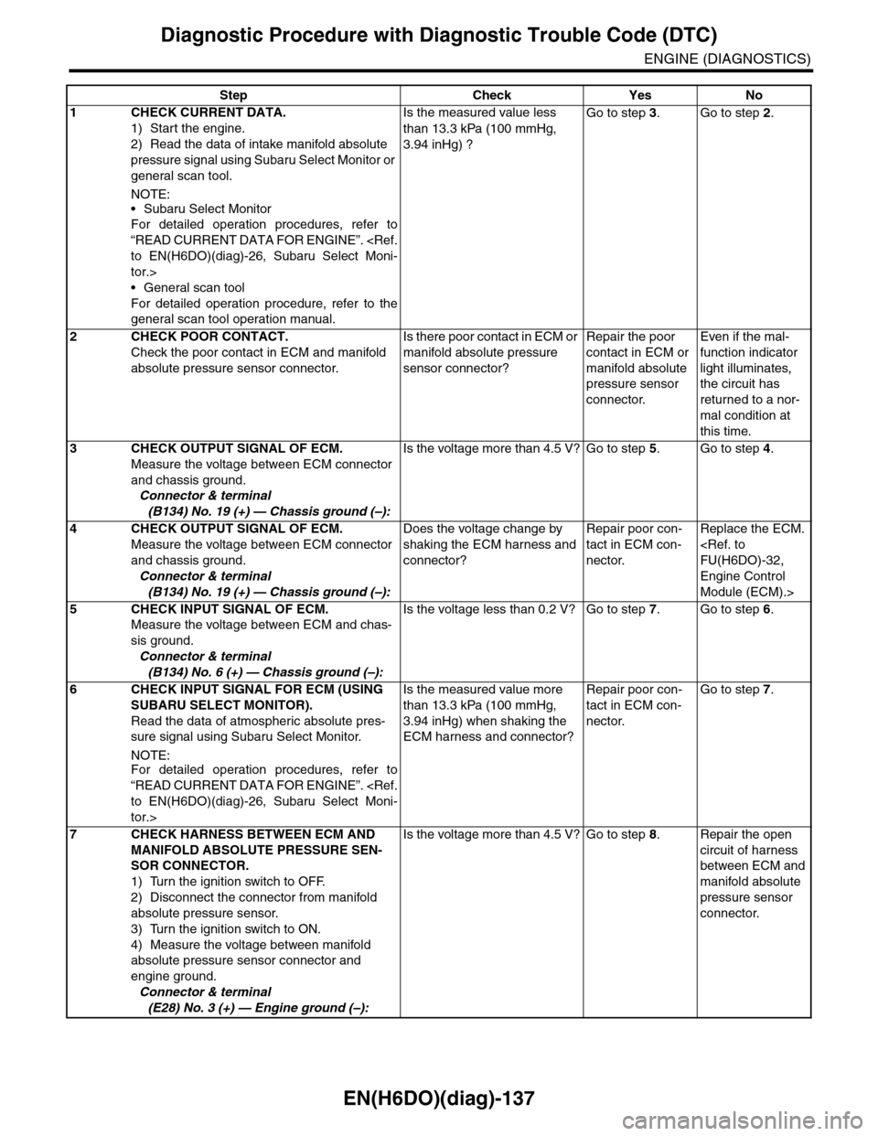
Step Check Yes No
1CHECK CURRENT DATA.
1) Start the engine.
2) Read the data of intake manifold absolute
pressure signal using Subaru Select Monitor or
general scan tool.
NOTE:
•Subaru Select Monitor
For detailed operation procedures, refer to
“READ CURRENT DATA FOR ENGINE”.
tor.>
•General scan tool
For detailed operation procedure, refer to the
general scan tool operation manual.
Is the measured value less
than 13.3 kPa (100 mmHg,
3.94 inHg) ?
Go to step 3.Go to step 2.
2CHECK POOR CONTACT.
Check the poor contact in ECM and manifold
absolute pressure sensor connector.
Is there poor contact in ECM or
manifold absolute pressure
sensor connector?
Repair the poor
contact in ECM or
manifold absolute
pressure sensor
connector.
Even if the mal-
function indicator
light illuminates,
the circuit has
returned to a nor-
mal condition at
this time.
3CHECK OUTPUT SIGNAL OF ECM.
Measure the voltage between ECM connector
and chassis ground.
Connector & terminal
(B134) No. 19 (+) — Chassis ground (–):
Is the voltage more than 4.5 V? Go to step 5.Go to step 4.
4CHECK OUTPUT SIGNAL OF ECM.
Measure the voltage between ECM connector
and chassis ground.
Connector & terminal
(B134) No. 19 (+) — Chassis ground (–):
Does the voltage change by
shaking the ECM harness and
connector?
Repair poor con-
tact in ECM con-
nector.
Replace the ECM.
Engine Control
Module (ECM).>
5CHECK INPUT SIGNAL OF ECM.
Measure the voltage between ECM and chas-
sis ground.
Connector & terminal
(B134) No. 6 (+) — Chassis ground (–):
Is the voltage less than 0.2 V? Go to step 7.Go to step 6.
6CHECK INPUT SIGNAL FOR ECM (USING
SUBARU SELECT MONITOR).
Read the data of atmospheric absolute pres-
sure signal using Subaru Select Monitor.
NOTE:For detailed operation procedures, refer to
“READ CURRENT DATA FOR ENGINE”.
tor.>
Is the measured value more
than 13.3 kPa (100 mmHg,
3.94 inHg) when shaking the
ECM harness and connector?
Repair poor con-
tact in ECM con-
nector.
Go to step 7.
7CHECK HARNESS BETWEEN ECM AND
MANIFOLD ABSOLUTE PRESSURE SEN-
SOR CONNECTOR.
1) Turn the ignition switch to OFF.
2) Disconnect the connector from manifold
absolute pressure sensor.
3) Turn the ignition switch to ON.
4) Measure the voltage between manifold
absolute pressure sensor connector and
engine ground.
Connector & terminal
(E28) No. 3 (+) — Engine ground (–):
Is the voltage more than 4.5 V? Go to step 8.Repair the open
circuit of harness
between ECM and
manifold absolute
pressure sensor
connector.
Page 1299 of 2453
EN(H6DO)(diag)-138
Diagnostic Procedure with Diagnostic Trouble Code (DTC)
ENGINE (DIAGNOSTICS)
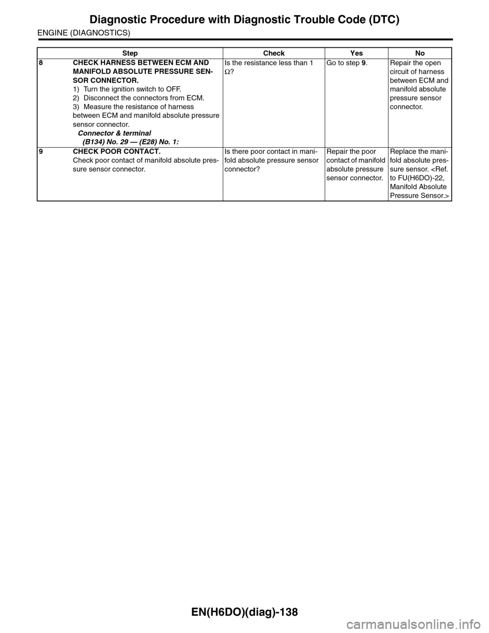
8CHECK HARNESS BETWEEN ECM AND
MANIFOLD ABSOLUTE PRESSURE SEN-
SOR CONNECTOR.
1) Turn the ignition switch to OFF.
2) Disconnect the connectors from ECM.
3) Measure the resistance of harness
between ECM and manifold absolute pressure
sensor connector.
Connector & terminal
(B134) No. 29 — (E28) No. 1:
Is the resistance less than 1
Ω?
Go to step 9.Repair the open
circuit of harness
between ECM and
manifold absolute
pressure sensor
connector.
9CHECK POOR CONTACT.
Check poor contact of manifold absolute pres-
sure sensor connector.
Is there poor contact in mani-
fold absolute pressure sensor
connector?
Repair the poor
contact of manifold
absolute pressure
sensor connector.
Replace the mani-
fold absolute pres-
sure sensor.
Manifold Absolute
Pressure Sensor.>
Step Check Yes No
Page 1300 of 2453
EN(H6DO)(diag)-139
Diagnostic Procedure with Diagnostic Trouble Code (DTC)
ENGINE (DIAGNOSTICS)
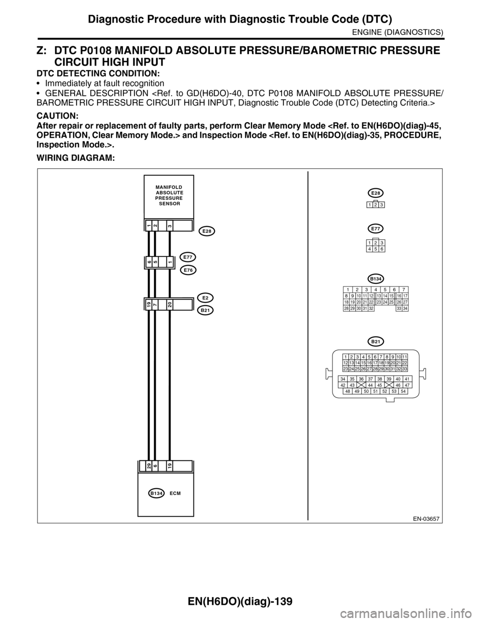
Z: DTC P0108 MANIFOLD ABSOLUTE PRESSURE/BAROMETRIC PRESSURE
CIRCUIT HIGH INPUT
DTC DETECTING CONDITION:
•Immediately at fault recognition
•GENERAL DESCRIPTION
CAUTION:
After repair or replacement of faulty parts, perform Clear Memory Mode
WIRING DIAGRAM:
EN-03657
29619
MANIFOLD ABSOLUTEPRESSURE SENSOR
19207B21
E2
132E28
ECMB134
B21
123412131415567816171819910 1120212223 24 25 2627 28 29 3031 32 33
3534 37363938 41404342 4445 47464948 51505352 54
651E77
E76
E28
123
E77
134562
B134
85610 11 12 13 14 157213416
3019 20 2228 29
91718252123 24323126 2733 34