Page 1541 of 2453
EN(H6DO)(diag)-380
Diagnostic Procedure with Diagnostic Trouble Code (DTC)
ENGINE (DIAGNOSTICS)
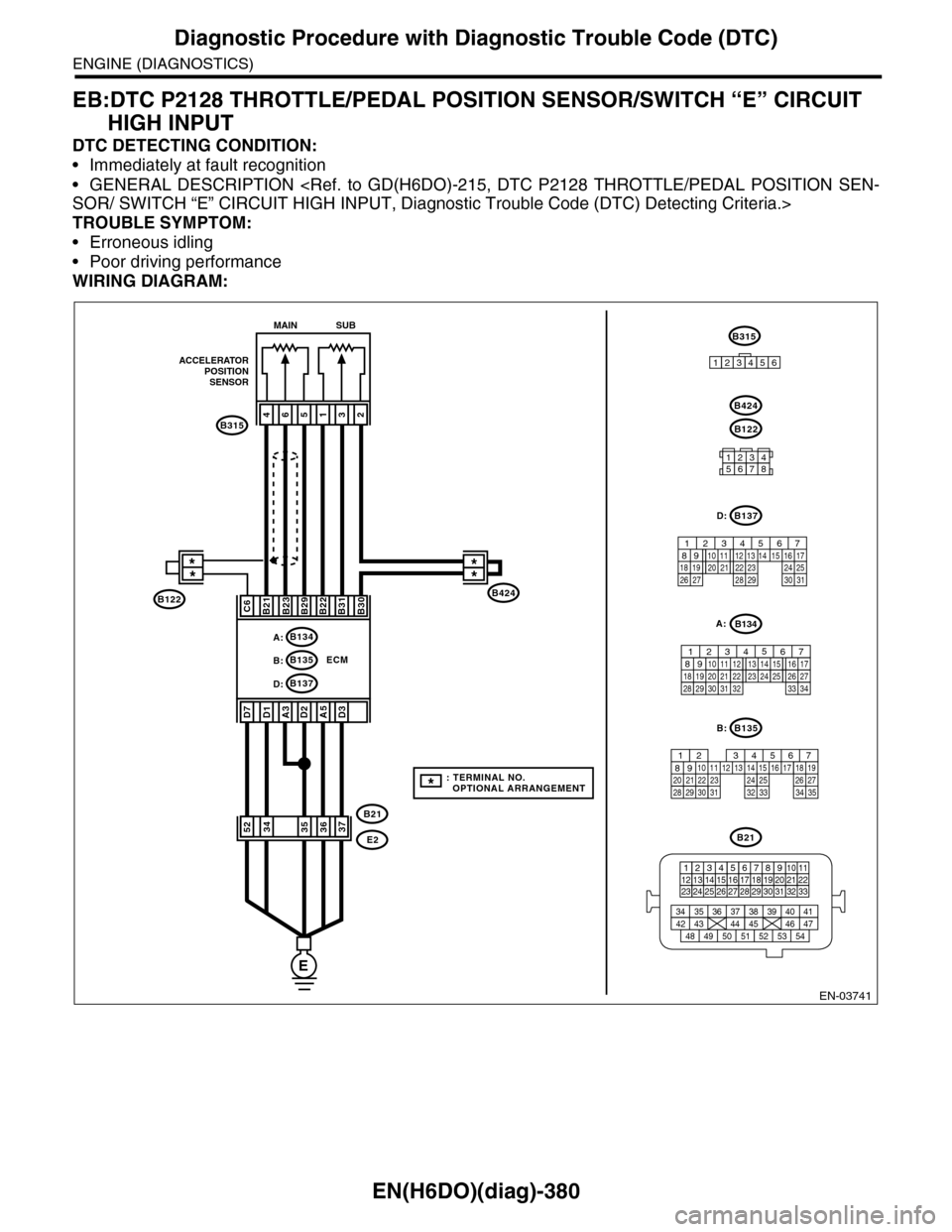
EB:DTC P2128 THROTTLE/PEDAL POSITION SENSOR/SWITCH “E” CIRCUIT
HIGH INPUT
DTC DETECTING CONDITION:
•Immediately at fault recognition
•GENERAL DESCRIPTION
SOR/ SWITCH “E” CIRCUIT HIGH INPUT, Diagnostic Trouble Code (DTC) Detecting Criteria.>
TROUBLE SYMPTOM:
•Erroneous idling
•Poor driving performance
WIRING DIAGRAM:
EN-03741
E
ECM
A:B134
B137D:
B424
B315
ACCELERATORPOSITIONSENSOR
**
465132
B21B23B29B22B31B30
A3D2
B21
E2
A5
MAIN SUB
B21
123412131415567816171819910 1120212223 24 25 2627 28 29 3031 32 33
3534 37363938 41404342 4445 47464948 51505352 54
B135
567821943102422 23 2511 12 13 14 1526 2728
16 17 18 1920 2129 30 31 32 33 34 35
B:
B137
5678219431022 2311 12 13 14 1524 2526
16 1718 19 20 2127 28 29 30 31
D:
12345678
B122
B424
D1D7
C6
B:B135
D3
3734355236
B122
B315
123456
**
*: TERMINAL NO. OPTIONAL ARRANGEMENT
B134
85610 11 12 13 14 157213416
3019 20 2228 29
91718252123 24323126 2733 34
A:
Page 1543 of 2453
EN(H6DO)(diag)-382
Diagnostic Procedure with Diagnostic Trouble Code (DTC)
ENGINE (DIAGNOSTICS)
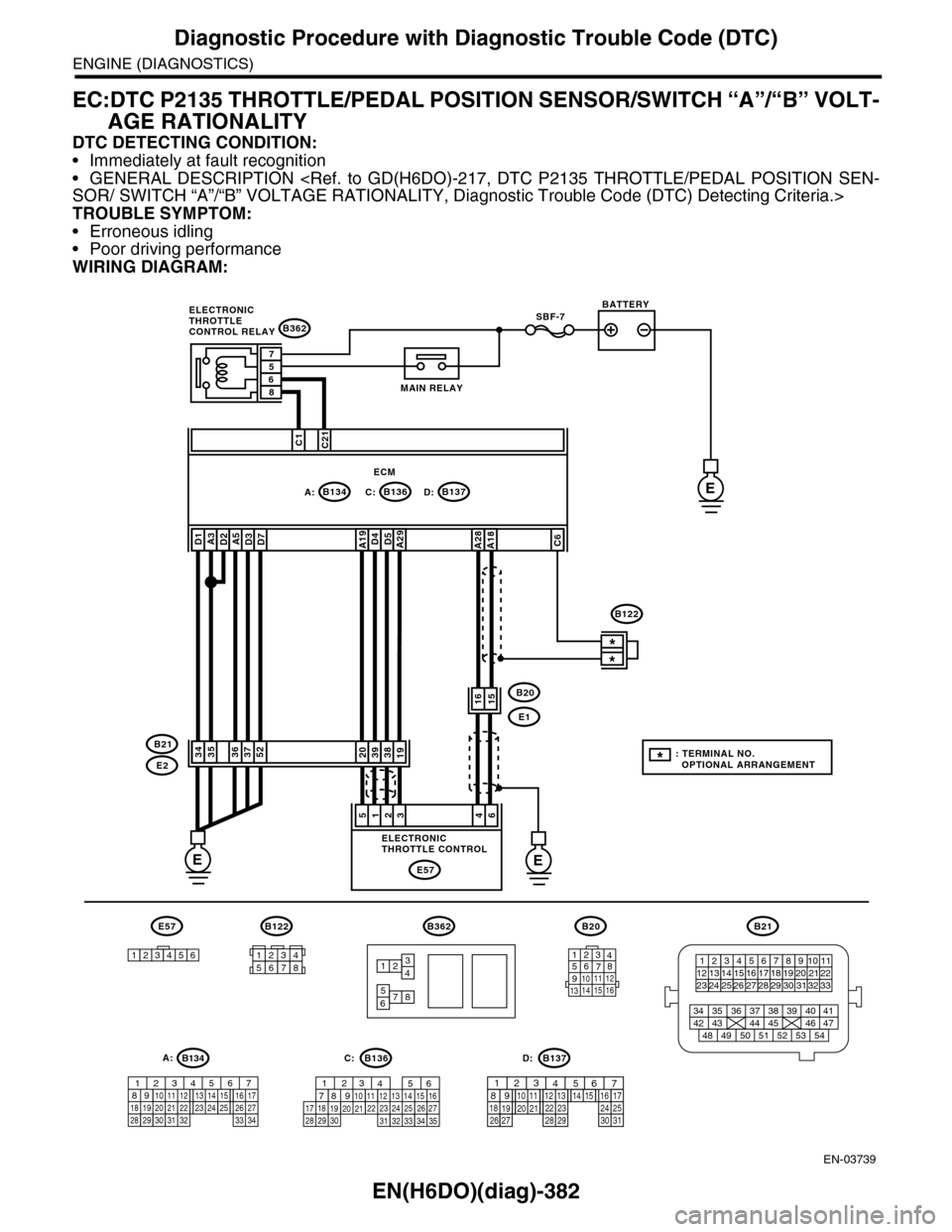
EC:DTC P2135 THROTTLE/PEDAL POSITION SENSOR/SWITCH “A”/“B” VOLT-
AGE RATIONALITY
DTC DETECTING CONDITION:
•Immediately at fault recognition
•GENERAL DESCRIPTION
SOR/ SWITCH “A”/“B” VOLTAGE RATIONALITY, Diagnostic Trouble Code (DTC) Detecting Criteria.>
TROUBLE SYMPTOM:
•Erroneous idling
•Poor driving performance
WIRING DIAGRAM:
EN-03739
SBF-7
B134A:B137B136D:
B362
E1
B20
C:E
EE
C1C21
38392019
1615
*
*
E2
B21
E57
461235
D4D5A29A19A5D3D7A3D2D1
3536375234
A28A18C6
ECM
57
86
B362
12
78
34
56
B21
12345678910 1112 1314 1516 1718 1920 21222324 25
34 35 36 37 38 39 40 41
48 49 50 51 52 53 5442 43 44 45 46 47
26 2728 2930 313233
B122
12345678
1289563410 11 121920 2129 3031
13 14 15161727281822 2324 25 267
32 3334 35
B136C:
12789563410 11 121920 2129 30 31
13 14 151617
27 281822 23 24 2526
B137D:
BATTERY
MAIN RELAY
ELECTRONICTHROTTLECONTROL RELAY
ELECTRONICTHROTTLE CONTROL
B20
1234567891011 121314 15 16
E57
123456
B122
*: TERMINAL NO. OPTIONAL ARRANGEMENT
A:B134
85610 11 12 13 14 157213416
3019 20 2228 29
91718252123 24323126 2733 34
Page 1547 of 2453
EN(H6DO)(diag)-386
Diagnostic Procedure with Diagnostic Trouble Code (DTC)
ENGINE (DIAGNOSTICS)
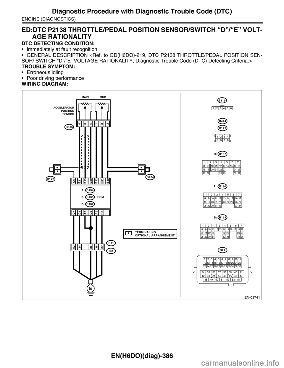
ED:DTC P2138 THROTTLE/PEDAL POSITION SENSOR/SWITCH “D”/“E” VOLT-
AGE RATIONALITY
DTC DETECTING CONDITION:
•Immediately at fault recognition
•GENERAL DESCRIPTION
SOR/ SWITCH “D”/“E” VOLTAGE RATIONALITY, Diagnostic Trouble Code (DTC) Detecting Criteria.>
TROUBLE SYMPTOM:
•Erroneous idling
•Poor driving performance
WIRING DIAGRAM:
EN-03741
E
ECM
A:B134
B137D:
B424
B315
ACCELERATORPOSITIONSENSOR
**
465132
B21B23B29B22B31B30
A3D2
B21
E2
A5
MAIN SUB
B21
123412131415567816171819910 1120212223 24 25 2627 28 29 3031 32 33
3534 37363938 41404342 4445 47464948 51505352 54
B135
567821943102422 23 2511 12 13 14 1526 2728
16 17 18 1920 2129 30 31 32 33 34 35
B:
B137
5678219431022 2311 12 13 14 1524 2526
16 1718 19 20 2127 28 29 30 31
D:
12345678
B122
B424
D1D7
C6
B:B135
D3
3734355236
B122
B315
123456
**
*: TERMINAL NO. OPTIONAL ARRANGEMENT
B134
85610 11 12 13 14 157213416
3019 20 2228 29
91718252123 24323126 2733 34
A:
Page 1854 of 2453
LU(H6DO)-5
Oil Pressure System
LUBRICATION
2. Oil Pressure System
A: WIRING DIAGRAM
LU-02159
E
i3
B38
i126
i127
B21
E2
14
E11
NO.5SBF-6MAIN SBF
B72
36
B10
i10
31
A4A3
B72
1345621234 5678910 11 12 13 14 15 16 17 18 19 20
B38B21
123412131415567816171819910 1120212223 24 25 2627 28 29 3031 32 33
3534 37363938 41404342 4445 47464948 51505352 54
A:
i11B:
BATTERYIGNITIONSWITCH
COMBINATIONMETER
OIL PRESSUREWA R N I N G L I G H T
OIL PRESSURESWITCH
1*1*
2*
i127
i126
123456789101112
1234567891011121314
i11B:
123456789101112131415161718192021222324252627282930
i10A:
2* :TERMINAL NO. OPTIONAL ARRANGEMENT AMONG 10, 11 AND 12
1*: TERMINAL NO. OPTIONAL ARRANGEMENT AMONG 7, 8 AND 9
Page 1866 of 2453
LU(H6DO)-17
General Diagnostics Table
LUBRICATION
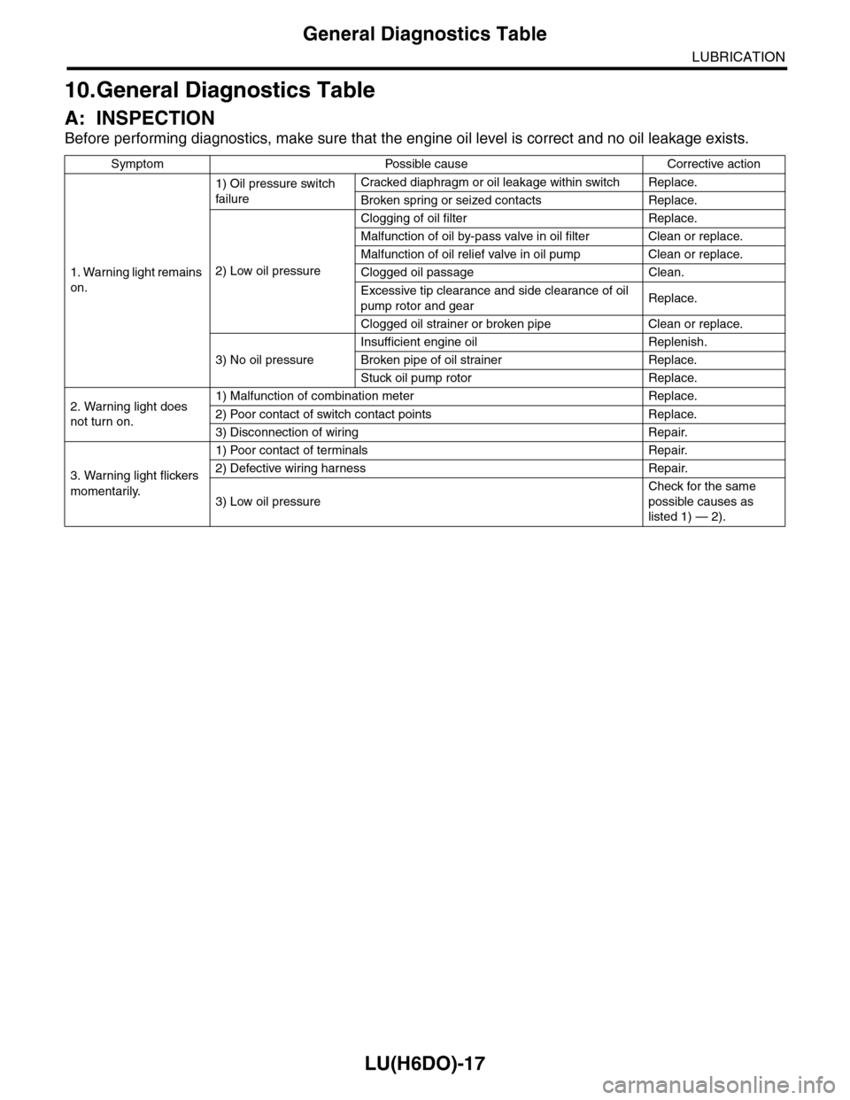
10.General Diagnostics Table
A: INSPECTION
Before performing diagnostics, make sure that the engine oil level is correct and no oil leakage exists.
Symptom Possible cause Corrective action
1. Warning light remains
on.
1) Oil pressure switch
failure
Cracked diaphragm or oil leakage within switch Replace.
Broken spring or seized contacts Replace.
2) Low oil pressure
Clogging of oil filter Replace.
Malfunction of oil by-pass valve in oil filter Clean or replace.
Malfunction of oil relief valve in oil pump Clean or replace.
Clogged oil passage Clean.
Excessive tip clearance and side clearance of oil
pump rotor and gearReplace.
Clogged oil strainer or broken pipe Clean or replace.
3) No oil pressure
Insufficient engine oil Replenish.
Broken pipe of oil strainer Replace.
Stuck oil pump rotor Replace.
2. Warning light does
not turn on.
1) Malfunction of combination meter Replace.
2) Poor contact of switch contact points Replace.
3) Disconnection of wiring Repair.
3. Warning light flickers
momentarily.
1) Poor contact of terminals Repair.
2) Defective wiring harness Repair.
3) Low oil pressure
Check for the same
possible causes as
listed 1) — 2).
Page 2122 of 2453
5AT(diag)-5
General Description
AUTOMATIC TRANSMISSION (DIAGNOSTICS)
3. General Description
A: CAUTION
•SRS AIRBAG SYSTEM
The airbag system wiring harness is routed near
the TCM.
CAUTION:
•All air bag system wiring harnesses and con-
nectors are colored yellow. Do not use an elec-
tric test equipment to check these circuits.
•Be careful not to damage the airbag system
wiring harness when performing diagnostics or
servicing the TCM.
•MEASUREMENT
When measuring the voltage and resistance of the
ECM, TCM or each sensor, use a tapered pin with
a diameter of less than 0.64 mm (0.025 in) in order
to avoid poor contact. Do not insert a pin of more
than 0.65 mm (0.026 in) diameter.
B: INSPECTION
1. BATTERY
Measure the battery voltage and specific gravity of
electrolyte.
Standard voltage: 12 V or more
Specific gravity: 1.260 or more
2. TRANSMISSION GROUND
Make sure that the ground terminal bolt is tightened
securely.
Tightening torque:
13 N·m (1.3 kgf-m, 9.4 ft-lb)
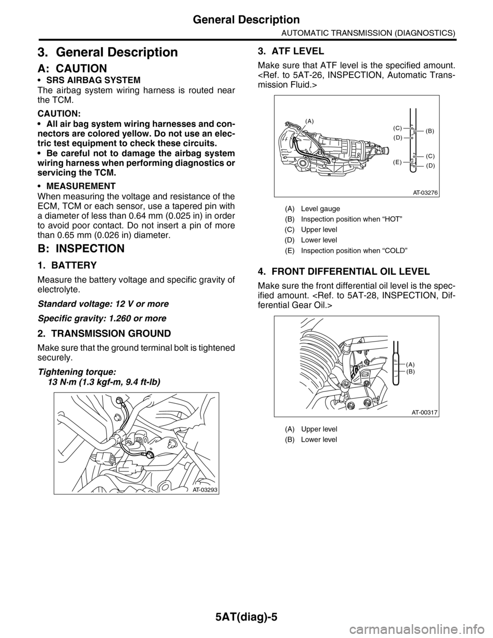
3. ATF LEVEL
Make sure that ATF level is the specified amount.
mission Fluid.>
4. FRONT DIFFERENTIAL OIL LEVEL
Make sure the front differential oil level is the spec-
ified amount.
ferential Gear Oil.>
AT-03293
(A) Level gauge
(B) Inspection position when “HOT”
(C) Upper level
(D) Lower level
(E) Inspection position when “COLD”
(A) Upper level
(B) Lower level
AT-03276
COLDLF
HOTLF
(C)
(D)
(C)
(D)
(E)
(B)
(A)
AT-00317
(A)(B)L
F
Page 2140 of 2453
5AT(diag)-23
SPORT Indicator Light Display
AUTOMATIC TRANSMISSION (DIAGNOSTICS)
B: INSPECTION
DIAGNOSIS:
SPORT indicator light circuit is open or shorted.
TROUBLE SYMPTOM:
When the ignition switch is turned to ON (engine OFF), SPORT indicator light does not illuminate.
WIRING DIAGRAM:
AT-03284
34
2930
COMBINATIONMETER
i10
i84A:B280B:
A27A26
B20B30
43
TCMB54
BODY INTEGRATED UNIT
SPORT
BATTERY
MAIN SBF SBF-6
IGNITIONSWITCH
NO.5
E
i84
8765432122232120191615141312111093435333217301831292827262524
A:
B280
87654321
2223212019161514131211109173018292827262524
B:
B54
12789563410 11 1219 20 2113 14 15 16 17 18222324
i10
123456789101112131415161718192021222324252627282930
Page 2142 of 2453
5AT(diag)-25
Diagnostic Procedure for Subaru Select Monitor Communication
AUTOMATIC TRANSMISSION (DIAGNOSTICS)
12.Diagnostic Procedure for Subaru Select Monitor Communication
A: COMMUNICATION FOR INITIALIZING IMPOSSIBLE
DIAGNOSIS:
Defective harness connector
TROUBLE SYMPTOM:
Subaru Select Monitor communication failure
WIRING DIAGRAM:
AT-03285
B21
12345678910111213 14 15 16
B54A:
12789563410 11 1219 20 2113 14 15 16 17 18222324
B55B:
12341011 121920 21135614 1578916 17 1822 23 24
IGNITIONSWITCH
P-VIGNRELAY
BATTERY
DATA LINKCONNECTOR
TRANSMISSION
B54A:B55
B357
B: TCM
B402
E
NO.5
NO.32SBF-6 MAIN SBF
A1
A19B21
B1B10A20
A5A14
1
12
10
13
NO.13
B21
E216
E
EE
A7A8A10
32
41
B402
123 8910413 14 15 165671112
B357
34
12