2009 SUBARU TRIBECA Control arm
[x] Cancel search: Control armPage 1695 of 2453
GD(H6DO)-83
Diagnostic Trouble Code (DTC) Detecting Criteria
GENERAL DESCRIPTION
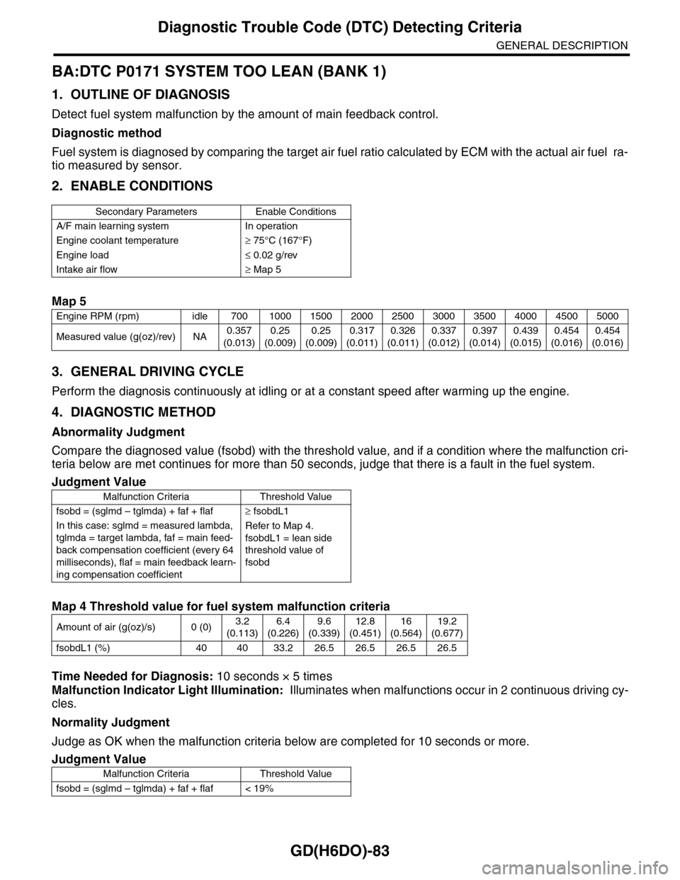
BA:DTC P0171 SYSTEM TOO LEAN (BANK 1)
1. OUTLINE OF DIAGNOSIS
Detect fuel system malfunction by the amount of main feedback control.
Diagnostic method
Fuel system is diagnosed by comparing the target air fuel ratio calculated by ECM with the actual air fuel ra-
tio measured by sensor.
2. ENABLE CONDITIONS
3. GENERAL DRIVING CYCLE
Perform the diagnosis continuously at idling or at a constant speed after warming up the engine.
4. DIAGNOSTIC METHOD
Abnormality Judgment
Compare the diagnosed value (fsobd) with the threshold value, and if a condition where the malfunction cri-
teria below are met continues for more than 50 seconds, judge that there is a fault in the fuel system.
Time Needed for Diagnosis: 10 seconds × 5 times
Malfunction Indicator Light Illumination: Illuminates when malfunctions occur in 2 continuous driving cy-
cles.
Normality Judgment
Judge as OK when the malfunction criteria below are completed for 10 seconds or more.
Secondary Parameters Enable Conditions
A/F main learning system In operation
Engine coolant temperature≥ 75°C (167°F)
Engine load≤ 0.02 g/rev
Intake air flow≥ Map 5
Map 5
Engine RPM (rpm) idle 700 1000 1500 2000 2500 3000 3500 4000 4500 5000
Measured value (g(oz)/rev) NA0.357
(0.013)
0.25
(0.009)
0.25
(0.009)
0.317
(0.011)
0.326
(0.011)
0.337
(0.012)
0.397
(0.014)
0.439
(0.015)
0.454
(0.016)
0.454
(0.016)
Judgment Value
Malfunction Criteria Threshold Value
fsobd = (sglmd – tglmda) + faf + flaf≥ fsobdL1
In this case: sglmd = measured lambda,
tglmda = target lambda, faf = main feed-
back compensation coefficient (every 64
milliseconds), flaf = main feedback learn-
ing compensation coefficient
Refer to Map 4.
fsobdL1 = lean side
threshold value of
fsobd
Map 4 Threshold value for fuel system malfunction criteria
Amount of air (g(oz)/s) 0 (0)3.2
(0.113)
6.4
(0.226)
9.6
(0.339)
12.8
(0.451)
16
(0.564)
19.2
(0.677)
fsobdL1 (%) 40 40 33.2 26.5 26.5 26.5 26.5
Judgment Value
Malfunction Criteria Threshold Value
fsobd = (sglmd – tglmda) + faf + flaf < 19%
Page 1697 of 2453
GD(H6DO)-85
Diagnostic Trouble Code (DTC) Detecting Criteria
GENERAL DESCRIPTION
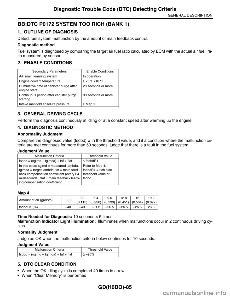
BB:DTC P0172 SYSTEM TOO RICH (BANK 1)
1. OUTLINE OF DIAGNOSIS
Detect fuel system malfunction by the amount of main feedback control.
Diagnostic method
Fuel system is diagnosed by comparing the target air fuel ratio calculated by ECM with the actual air fuel ra-
tio measured by sensor.
2. ENABLE CONDITIONS
3. GENERAL DRIVING CYCLE
Perform the diagnosis continuously at idling or at a constant speed after warming up the engine.
4. DIAGNOSTIC METHOD
Abnormality Judgment
Compare the diagnosed value (fsobd) with the threshold value, and if a condition where the malfunction cri-
teria are met continues for more than 50 seconds, judge that there is a fault in the fuel system.
Time Needed for Diagnosis: 10 seconds × 5 times
Malfunction Indicator Light Illumination: Illuminates when malfunctions occur in 2 continuous driving cy-
cles.
Normality Judgment
Judge as OK when the malfunction criteria below continues for 10 seconds.
5. DTC CLEAR CONDITION
•When the OK idling cycle is completed 40 times in a row
•When “Clear Memory” is performed
Secondary Parameters Enable Conditions
A/F main learning system In operation
Engine coolant temperature≥ 75°C (167°F)
Cumulative time of canister purge after
engine start
20 seconds or more
Continuous period after canister purge
starting
30 seconds or more
Intake manifold absolute pressure≥ Map 1
Judgment Value
Malfunction Criteria Threshold Value
fsobd = (sglmd – tglmda) + faf + flaf≤ fsobdR1
In this case: sglmd = measured lambda,
tglmda = target lambda, faf = main feed-
back compensation coefficient (every 64
milliseconds), flaf = main feedback learn-
ing compensation coefficient
Refer to Map 4.
fsobdR1 = rich side
threshold value of
fsobd
Map 4
Amount of air (g(oz)/s) 0 (0)3.2
(0.113)
6.4
(0.226)
9.6
(0.339)
12.8
(0.451)
16
(0.564)
19.2
(0.677)
fsobdR1 (%) –40 –40 –31.2 –26.5 –26.5 –26.5 26.5
Judgment Value
Malfunction Criteria Threshold Value
fsobd = (sglmd – tglmda) + faf + flaf≥ –20%
Page 1775 of 2453
GD(H6DO)-163
Diagnostic Trouble Code (DTC) Detecting Criteria
GENERAL DESCRIPTION
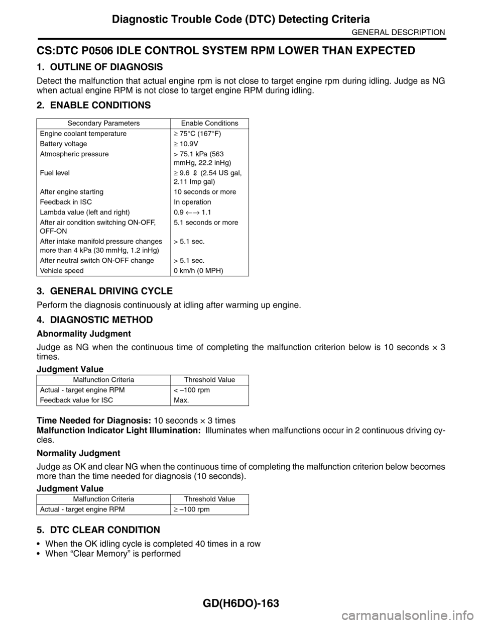
CS:DTC P0506 IDLE CONTROL SYSTEM RPM LOWER THAN EXPECTED
1. OUTLINE OF DIAGNOSIS
Detect the malfunction that actual engine rpm is not close to target engine rpm during idling. Judge as NG
when actual engine RPM is not close to target engine RPM during idling.
2. ENABLE CONDITIONS
3. GENERAL DRIVING CYCLE
Perform the diagnosis continuously at idling after warming up engine.
4. DIAGNOSTIC METHOD
Abnormality Judgment
Judge as NG when the continuous time of completing the malfunction criterion below is 10 seconds × 3
times.
Time Needed for Diagnosis: 10 seconds × 3 times
Malfunction Indicator Light Illumination: Illuminates when malfunctions occur in 2 continuous driving cy-
cles.
Normality Judgment
Judge as OK and clear NG when the continuous time of completing the malfunction criterion below becomes
more than the time needed for diagnosis (10 seconds).
5. DTC CLEAR CONDITION
•When the OK idling cycle is completed 40 times in a row
•When “Clear Memory” is performed
Secondary Parameters Enable Conditions
Engine coolant temperature≥ 75°C (167°F)
Battery voltage≥ 10.9V
Atmospheric pressure > 75.1 kPa (563
mmHg, 22.2 inHg)
Fuel level≥ 9.6 2 (2.54 US gal,
2.11 Imp gal)
After engine starting 10 seconds or more
Feedback in ISC In operation
Lambda value (left and right) 0.9 ←→ 1.1
After air condition switching ON-OFF,
OFF-ON
5.1 seconds or more
After intake manifold pressure changes
more than 4 kPa (30 mmHg, 1.2 inHg)
> 5.1 sec.
After neutral switch ON-OFF change > 5.1 sec.
Ve h i c l e s p e e d 0 k m / h ( 0 M P H )
Judgment Value
Malfunction Criteria Threshold Value
Actual - target engine RPM < –100 rpm
Feedback value for ISC Max.
Judgment Value
Malfunction Criteria Threshold Value
Actual - target engine RPM≥ –100 rpm
Page 1777 of 2453
GD(H6DO)-165
Diagnostic Trouble Code (DTC) Detecting Criteria
GENERAL DESCRIPTION
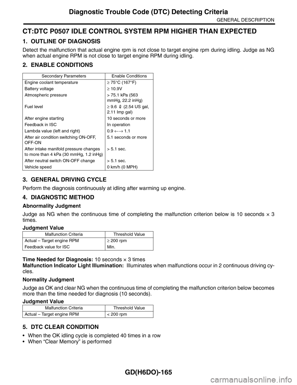
CT:DTC P0507 IDLE CONTROL SYSTEM RPM HIGHER THAN EXPECTED
1. OUTLINE OF DIAGNOSIS
Detect the malfunction that actual engine rpm is not close to target engine rpm during idling. Judge as NG
when actual engine RPM is not close to target engine RPM during idling.
2. ENABLE CONDITIONS
3. GENERAL DRIVING CYCLE
Perform the diagnosis continuously at idling after warming up engine.
4. DIAGNOSTIC METHOD
Abnormality Judgment
Judge as NG when the continuous time of completing the malfunction criterion below is 10 seconds × 3
times.
Time Needed for Diagnosis: 10 seconds × 3 times
Malfunction Indicator Light Illumination: Illuminates when malfunctions occur in 2 continuous driving cy-
cles.
Normality Judgment
Judge as OK and clear NG when the continuous time of completing the malfunction criterion below becomes
more than the time needed for diagnosis (10 seconds).
5. DTC CLEAR CONDITION
•When the OK idling cycle is completed 40 times in a row
•When “Clear Memory” is performed
Secondary Parameters Enable Conditions
Engine coolant temperature≥ 75°C (167°F)
Battery voltage≥ 10.9V
Atmospheric pressure > 75.1 kPa (563
mmHg, 22.2 inHg)
Fuel level≥ 9.6 2 (2.54 US gal,
2.11 Imp gal)
After engine starting 10 seconds or more
Feedback in ISC In operation
Lambda value (left and right) 0.9 ←→ 1.1
After air condition switching ON-OFF,
OFF-ON
5.1 seconds or more
After intake manifold pressure changes
to more than 4 kPa (30 mmHg, 1.2 inHg)
> 5.1 sec.
After neutral switch ON-OFF change > 5.1 sec.
Ve h i c l e s p e e d 0 k m / h ( 0 M P H )
Judgment Value
Malfunction Criteria Threshold Value
Actual – Target engine RPM≥ 200 rpm
Feedback value for ISC Min.
Judgment Value
Malfunction Criteria Threshold Value
Actual – Target engine RPM < 200 rpm
Page 1889 of 2453
ME(H6DO)-23
Ignition Timing
MECHANICAL
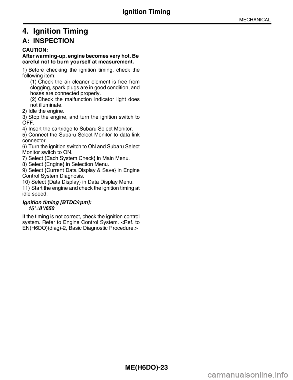
4. Ignition Timing
A: INSPECTION
CAUTION:
After warming-up, engine becomes very hot. Be
careful not to burn yourself at measurement.
1) Before checking the ignition timing, check the
following item:
(1) Check the air cleaner element is free from
clogging, spark plugs are in good condition, and
hoses are connected properly.
(2) Check the malfunction indicator light does
not illuminate.
2) Idle the engine.
3) Stop the engine, and turn the ignition switch to
OFF.
4) Insert the cartridge to Subaru Select Monitor.
5) Connect the Subaru Select Monitor to data link
connector.
6) Turn the ignition switch to ON and Subaru Select
Monitor switch to ON.
7) Select {Each System Check} in Main Menu.
8) Select {Engine} in Selection Menu.
9) Select {Current Data Display & Save} in Engine
Control System Diagnosis.
10) Select {Data Display} in Data Display Menu.
11) Start the engine and check the ignition timing at
idle speed.
Ignition timing [BTDC/rpm]:
15°±8°/650
If the timing is not correct, check the ignition control
system. Refer to Engine Control System.
Page 1960 of 2453
SC(H6DO)-2
General Description
STARTING/CHARGING SYSTEMS
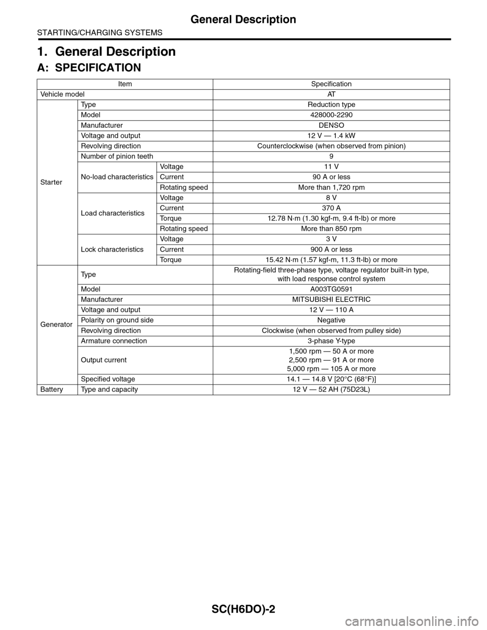
1. General Description
A: SPECIFICATION
Item Specification
Ve h i c l e m o d e lAT
Starter
Ty p e R e d u c t i o n t y p e
Model 428000-2290
Manufacturer DENSO
Vo l t a g e a n d o u t p u t 1 2 V — 1 . 4 k W
Revolving direction Counterclockwise (when observed from pinion)
Number of pinion teeth 9
No-load characteristics
Vo l t a g e 1 1 V
Current 90 A or less
Rotating speed More than 1,720 rpm
Load characteristics
Vo l t a g e 8 V
Current 370 A
To r q u e 1 2 . 7 8 N · m ( 1 . 3 0 k g f - m , 9 . 4 f t - l b ) o r m o r e
Rotating speed More than 850 rpm
Lock characteristics
Vo l t a g e 3 V
Current 900 A or less
To r q u e 1 5 . 4 2 N · m ( 1 . 5 7 k g f - m , 1 1 . 3 f t - l b ) o r m o r e
Generator
Ty p eRotating-field three-phase type, voltage regulator built-in type,
with load response control system
Model A003TG0591
Manufacturer MITSUBISHI ELECTRIC
Vo l t a g e a n d o u t p u t 1 2 V — 1 1 0 A
Po la r i t y on gr ou n d s id e N e g at i ve
Revolving direction Clockwise (when observed from pulley side)
Armature connection 3-phase Y-type
Output current
1,500 rpm — 50 A or more
2,500 rpm — 91 A or more
5,000 rpm — 105 A or more
Specified voltage 14.1 — 14.8 V [20°C (68°F)]
Battery Type and capacity 12 V — 52 AH (75D23L)
Page 2128 of 2453
5AT(diag)-11
Transmission Control Module (TCM) I/O Signal
AUTOMATIC TRANSMISSION (DIAGNOSTICS)
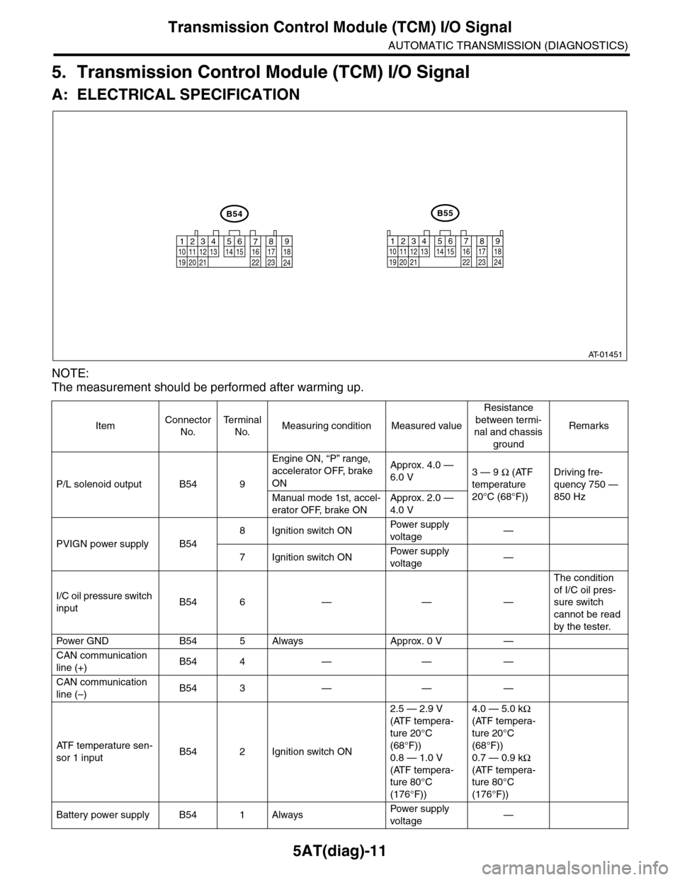
5. Transmission Control Module (TCM) I/O Signal
A: ELECTRICAL SPECIFICATION
NOTE:
The measurement should be performed after warming up.
ItemConnector
No.
Te r m i n a l
No.Measuring condition Measured value
Resistance
between termi-
nal and chassis
ground
Remarks
P/L solenoid output B54 9
Engine ON, “P” range,
accelerator OFF, brake
ON
Approx. 4.0 —
6.0 V3 — 9 Ω (ATF
temperature
20°C (68°F))
Driving fre-
quency 750 —
850 HzManual mode 1st, accel-
erator OFF, brake ON
Approx. 2.0 —
4.0 V
PVIGN power supply B54
8Ignition switch ONPow er s up p ly
voltage—
7Ignition switch ONPow er s up p ly
voltage—
I/C oil pressure switch
inputB54 6 — — —
The condition
of I/C oil pres-
sure switch
cannot be read
by the tester.
Pow er G N D B 5 4 5 A lways A pp r ox . 0 V —
CAN communication
line (+)B54 4 — — —
CAN communication
line (–)B54 3 — — —
AT F t e m p e r a t u r e s e n -
sor 1 inputB54 2 Ignition switch ON
2.5 — 2.9 V
(ATF tempera-
ture 20°C
(68°F))
0.8 — 1.0 V
(ATF tempera-
ture 80°C
(176°F))
4.0 — 5.0 kΩ
(ATF tempera-
ture 20°C
(68°F))
0.7 — 0.9 kΩ
(ATF tempera-
ture 80°C
(176°F))
Battery power supply B54 1 AlwaysPow er s up p ly
voltage—
AT-01451
12341011 121920 21135614 1578916 17 1822 23 24
12789563410 11 1219 20 2113 14 15 16 17 18222324
B55B54
Page 2138 of 2453
5AT(diag)-21
Learning Control
AUTOMATIC TRANSMISSION (DIAGNOSTICS)
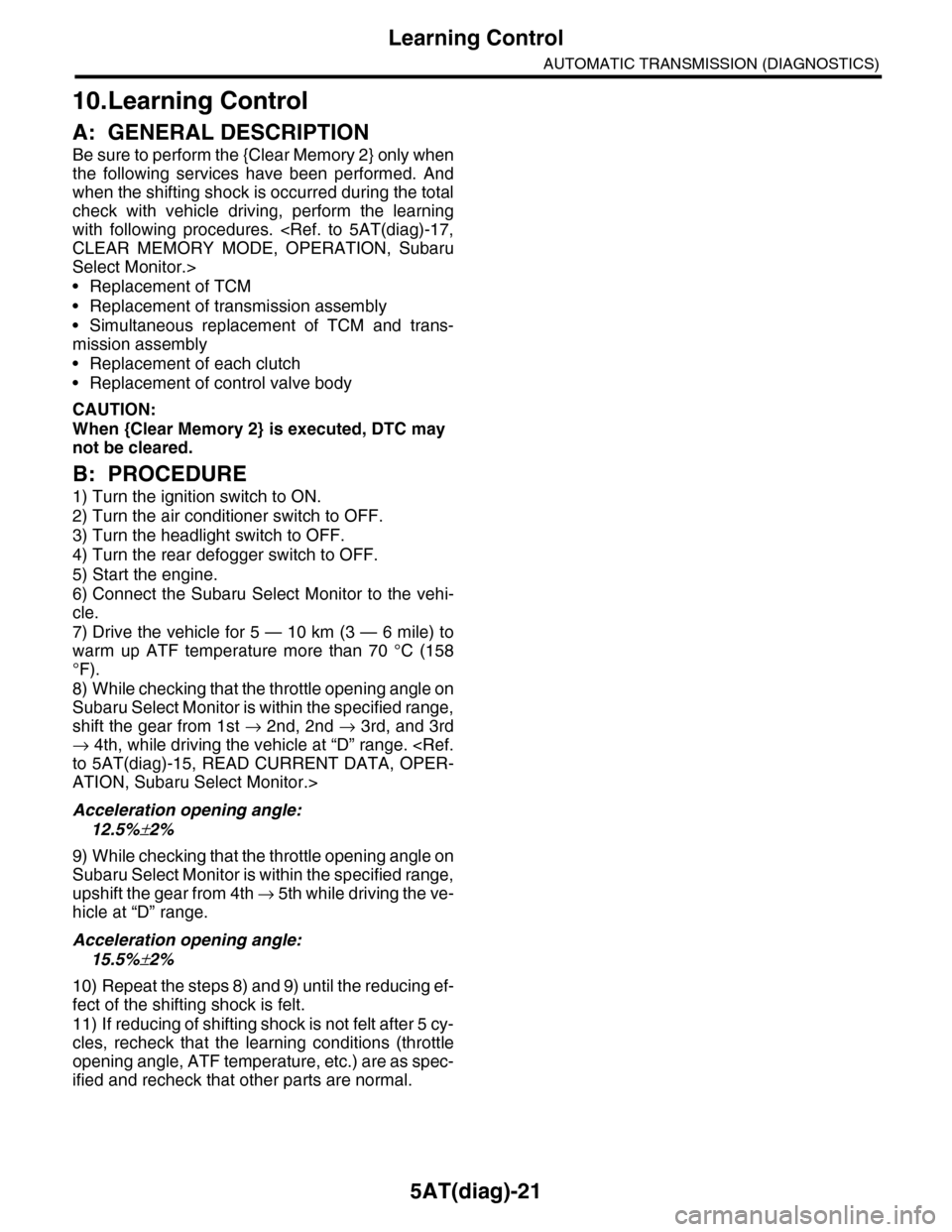
10.Learning Control
A: GENERAL DESCRIPTION
Be sure to perform the {Clear Memory 2} only when
the following services have been performed. And
when the shifting shock is occurred during the total
check with vehicle driving, perform the learning
with following procedures.
Select Monitor.>
•Replacement of TCM
•Replacement of transmission assembly
•Simultaneous replacement of TCM and trans-
mission assembly
•Replacement of each clutch
•Replacement of control valve body
CAUTION:
When {Clear Memory 2} is executed, DTC may
not be cleared.
B: PROCEDURE
1) Turn the ignition switch to ON.
2) Turn the air conditioner switch to OFF.
3) Turn the headlight switch to OFF.
4) Turn the rear defogger switch to OFF.
5) Start the engine.
6) Connect the Subaru Select Monitor to the vehi-
cle.
7) Drive the vehicle for 5 — 10 km (3 — 6 mile) to
warm up ATF temperature more than 70 °C (158
°F).
8) While checking that the throttle opening angle on
Subaru Select Monitor is within the specified range,
shift the gear from 1st → 2nd, 2nd → 3rd, and 3rd
→ 4th, while driving the vehicle at “D” range.
ATION, Subaru Select Monitor.>
Acceleration opening angle:
12.5%±2%
9) While checking that the throttle opening angle on
Subaru Select Monitor is within the specified range,
upshift the gear from 4th → 5 t h w h i l e d r i v i n g t h e v e -
hicle at “D” range.
Acceleration opening angle:
15.5%±2%
10) Repeat the steps 8) and 9) until the reducing ef-
fect of the shifting shock is felt.
11) If reducing of shifting shock is not felt after 5 cy-
cles, recheck that the learning conditions (throttle
opening angle, ATF temperature, etc.) are as spec-
ified and recheck that other parts are normal.