Page 2171 of 2453

5AT(diag)-54
Diagnostic Procedure with Diagnostic Trouble Code (DTC)
AUTOMATIC TRANSMISSION (DIAGNOSTICS)
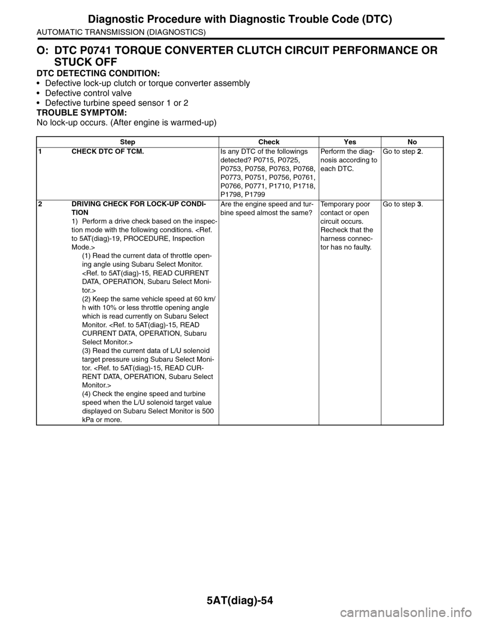
O: DTC P0741 TORQUE CONVERTER CLUTCH CIRCUIT PERFORMANCE OR
STUCK OFF
DTC DETECTING CONDITION:
•Defective lock-up clutch or torque converter assembly
•Defective control valve
•Defective turbine speed sensor 1 or 2
TROUBLE SYMPTOM:
No lock-up occurs. (After engine is warmed-up)
Step Check Yes No
1CHECK DTC OF TCM.Is any DTC of the followings
detected? P0715, P0725,
P0753, P0758, P0763, P0768,
P0773, P0751, P0756, P0761,
P0766, P0771, P1710, P1718,
P1798, P1799
Pe r for m t h e d ia g -
nosis according to
each DTC.
Go to step 2.
2DRIVING CHECK FOR LOCK-UP CONDI-
TION
1) Perform a drive check based on the inspec-
tion mode with the following conditions.
to 5AT(diag)-19, PROCEDURE, Inspection
Mode.>
(1) Read the current data of throttle open-
ing angle using Subaru Select Monitor.
DATA, O PER ATION, Subar u Select Moni-
tor.>
(2) Keep the same vehicle speed at 60 km/
h with 10% or less throttle opening angle
which is read currently on Subaru Select
Monitor.
CURRENT DATA, OPERATION, Subaru
Select Monitor.>
(3) Read the current data of L/U solenoid
target pressure using Subaru Select Moni-
tor.
RENT DATA, OPERATION, Subaru Select
Monitor.>
(4) Check the engine speed and turbine
speed when the L/U solenoid target value
displayed on Subaru Select Monitor is 500
kPa or more.
Are the engine speed and tur-
bine speed almost the same?
Te m p o r a r y p o o r
contact or open
circuit occurs.
Recheck that the
harness connec-
tor has no faulty.
Go to step 3.
Page 2255 of 2453

CS-3
General Description
CONTROL SYSTEMS
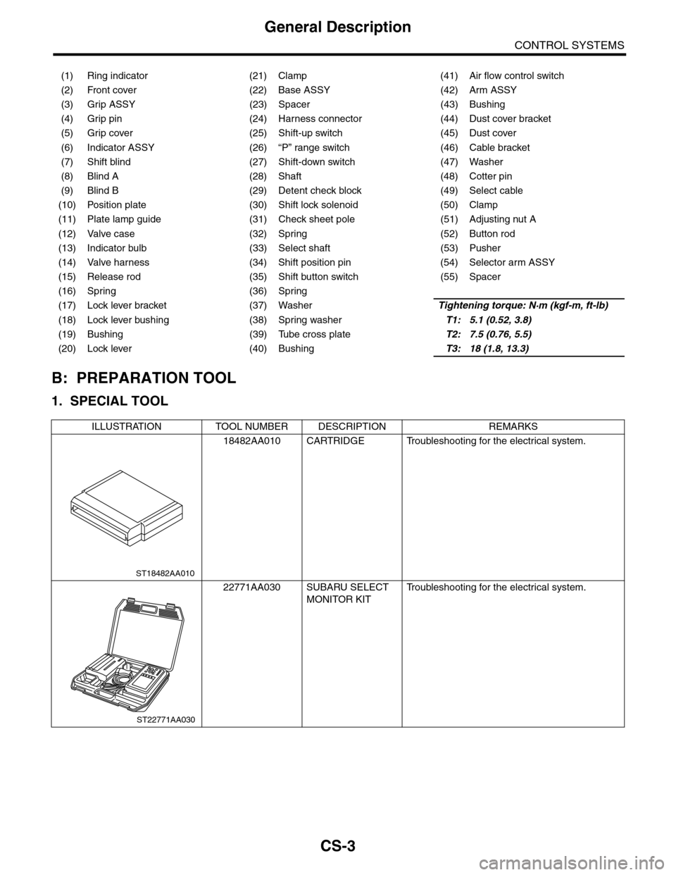
B: PREPARATION TOOL
1. SPECIAL TOOL
(1) Ring indicator (21) Clamp (41) Air flow control switch
(2) Front cover (22) Base ASSY (42) Arm ASSY
(3) Grip ASSY (23) Spacer (43) Bushing
(4) Grip pin (24) Harness connector (44) Dust cover bracket
(5) Grip cover (25) Shift-up switch (45) Dust cover
(6) Indicator ASSY (26) “P” range switch (46) Cable bracket
(7) Shift blind (27) Shift-down switch (47) Washer
(8) Blind A (28) Shaft (48) Cotter pin
(9) Blind B (29) Detent check block (49) Select cable
(10) Position plate (30) Shift lock solenoid (50) Clamp
(11) Plate lamp guide (31) Check sheet pole (51) Adjusting nut A
(12) Valve case (32) Spring (52) Button rod
(13) Indicator bulb (33) Select shaft (53) Pusher
(14) Valve harness (34) Shift position pin (54) Selector arm ASSY
(15) Release rod (35) Shift button switch (55) Spacer
(16) Spring (36) Spring
(17) Lock lever bracket (37) WasherTightening torque: N·m (kgf-m, ft-lb)
(18) Lock lever bushing (38) Spring washerT1: 5.1 (0.52, 3.8)
(19) Bushing (39) Tube cross plateT2: 7.5 (0.76, 5.5)
(20) Lock lever (40) BushingT3: 18 (1.8, 13.3)
ILLUSTRATION TOOL NUMBER DESCRIPTION REMARKS
18482AA010 CARTRIDGE Troubleshooting for the electrical system.
22771AA030 SUBARU SELECT
MONITOR KIT
Tr o u b l e s h o o t i n g f o r t h e e l e c t r i c a l s y s t e m .
ST18482AA010
ST22771AA030
Page 2271 of 2453

CS-19
Select Lever
CONTROL SYSTEMS
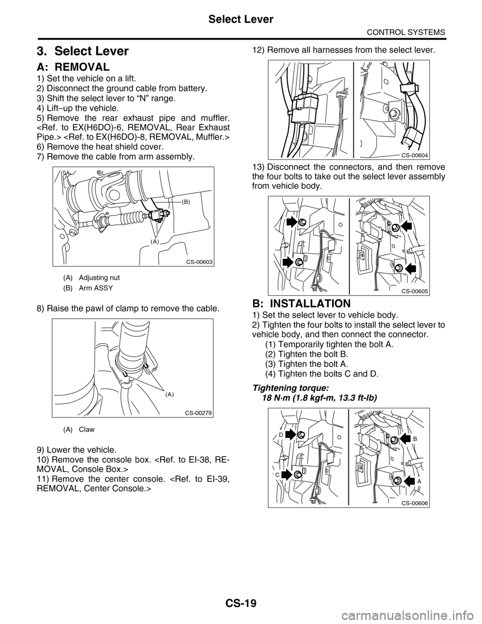
3. Select Lever
A: REMOVAL
1) Set the vehicle on a lift.
2) Disconnect the ground cable from battery.
3) Shift the select lever to “N” range.
4) Lift–up the vehicle.
5) Remove the rear exhaust pipe and muffler.
Pipe.>
6) Remove the heat shield cover.
7) Remove the cable from arm assembly.
8) Raise the pawl of clamp to remove the cable.
9) Lower the vehicle.
10) Remove the console box.
MOVAL, Console Box.>
11) Remove the center console.
REMOVAL, Center Console.>
12) Remove all harnesses from the select lever.
13) Disconnect the connectors, and then remove
the four bolts to take out the select lever assembly
from vehicle body.
B: INSTALLATION
1) Set the select lever to vehicle body.
2) Tighten the four bolts to install the select lever to
vehicle body, and then connect the connector.
(1) Temporarily tighten the bolt A.
(2) Tighten the bolt B.
(3) Tighten the bolt A.
(4) Tighten the bolts C and D.
Tightening torque:
18 N·m (1.8 kgf-m, 13.3 ft-lb)
(A) Adjusting nut
(B) Arm ASSY
(A) Claw
CS-00603
(A)
(B)
CS-00279
(A)
CS-00604
CS-00605
CS-00606
D
A
B
C
Page 2275 of 2453
CS-23
Select Lever
CONTROL SYSTEMS
20) Remove the lock lever.
21) Remove the release rod and spring.
22) Remove the cable bracket.
23) Remove the spacer.
24) Remove the dust cover and dust cover bracket.
25) Remove the spacer.
26) Using a press, remove the shift position pin.
27) Remove the clips, then remove the shaft.
28) Remove the arm assembly.
CS-00625
CS-00626
CS-00627
CS-00628
(A) Dust cover
(B) Dust cover bracket
CS-00629
(B)(A)
CS-00630
CS-00631
CS-00632
Page 2276 of 2453
CS-24
Select Lever
CONTROL SYSTEMS
29) Remove the bushing.
30) Remove the selector arm assembly.
31) Remove the clip while being careful not to
break the pin, then remove the shift button switch.
32) Remove the select shaft.
33) Remove the tube cross plate.
34) Remove the mode change switch.
35) Remove the detent check block.
CS-00634
CS-00635
CS-00636
CS-00637
CS-00638
CS-00639
CS-00640
Page 2278 of 2453

CS-26
Select Cable
CONTROL SYSTEMS
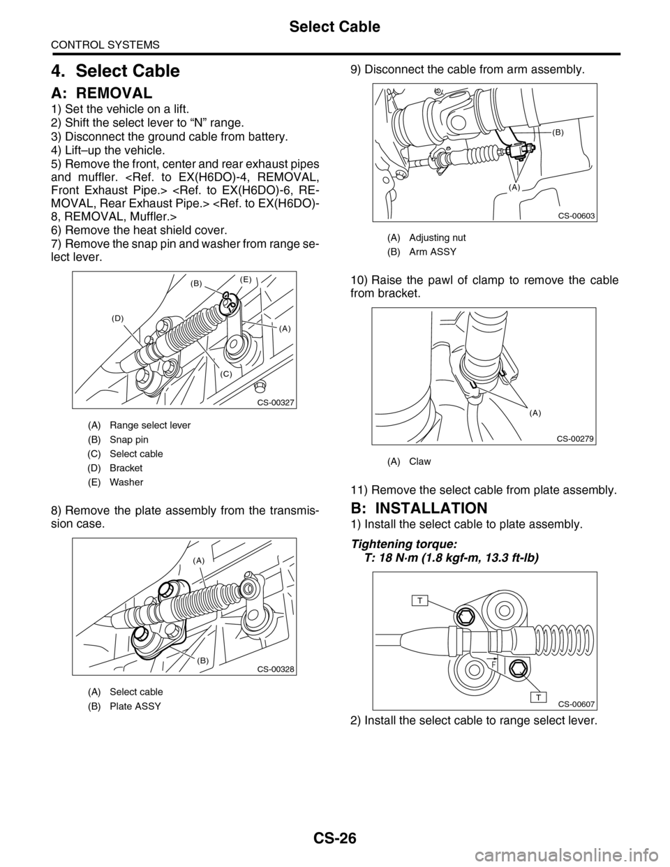
4. Select Cable
A: REMOVAL
1) Set the vehicle on a lift.
2) Shift the select lever to “N” range.
3) Disconnect the ground cable from battery.
4) Lift–up the vehicle.
5) Remove the front, center and rear exhaust pipes
and muffler.
Front Exhaust Pipe.>
MOVAL, Rear Exhaust Pipe.>
8, REMOVAL, Muffler.>
6) Remove the heat shield cover.
7) Remove the snap pin and washer from range se-
lect lever.
8) Remove the plate assembly from the transmis-
sion case.
9) Disconnect the cable from arm assembly.
10) Raise the pawl of clamp to remove the cable
from bracket.
11) Remove the select cable from plate assembly.
B: INSTALLATION
1) Install the select cable to plate assembly.
Tightening torque:
T: 18 N·m (1.8 kgf-m, 13.3 ft-lb)
2) Install the select cable to range select lever.
(A) Range select lever
(B) Snap pin
(C) Select cable
(D) Bracket
(E) Washer
(A) Select cable
(B) Plate ASSY
CS-00327
(B)
(D)
(C)
(E)
(A)
(A)
(B)CS-00328
(A) Adjusting nut
(B) Arm ASSY
(A) Claw
CS-00603
(A)
(B)
CS-00279
(A)
CS-00607
T
T