2009 SUBARU TRIBECA Control arm
[x] Cancel search: Control armPage 1043 of 2453
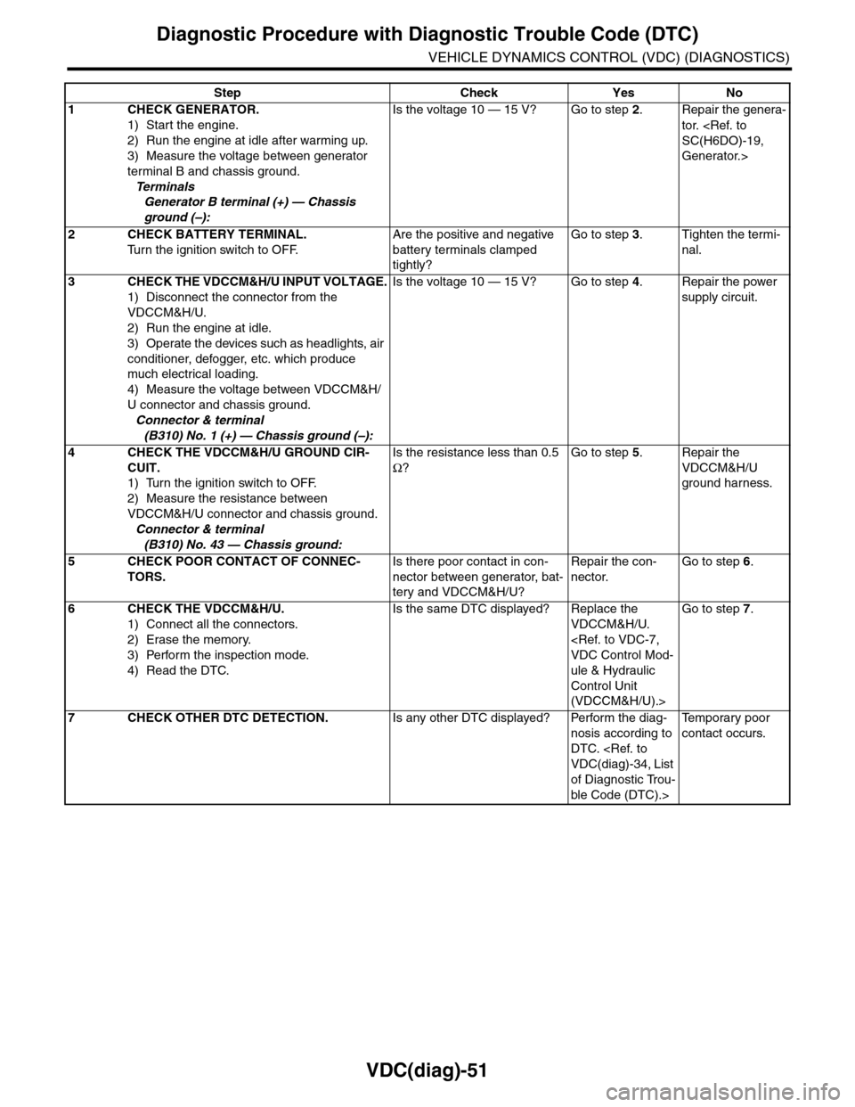
VDC(diag)-51
Diagnostic Procedure with Diagnostic Trouble Code (DTC)
VEHICLE DYNAMICS CONTROL (VDC) (DIAGNOSTICS)
Step Check Yes No
1CHECK GENERATOR.
1) Start the engine.
2) Run the engine at idle after warming up.
3) Measure the voltage between generator
terminal B and chassis ground.
Te r m i n a l s
Generator B terminal (+) — Chassis
ground (–):
Is the voltage 10 — 15 V? Go to step 2.Repair the genera-
tor.
Generator.>
2CHECK BATTERY TERMINAL.
Tu r n t h e i g n i t i o n s w i t c h t o O F F.
Are the positive and negative
battery terminals clamped
tightly?
Go to step 3.Tighten the termi-
nal.
3CHECK THE VDCCM&H/U INPUT VOLTAGE.
1) Disconnect the connector from the
VDCCM&H/U.
2) Run the engine at idle.
3) Operate the devices such as headlights, air
conditioner, defogger, etc. which produce
much electrical loading.
4) Measure the voltage between VDCCM&H/
U connector and chassis ground.
Connector & terminal
(B310) No. 1 (+) — Chassis ground (–):
Is the voltage 10 — 15 V? Go to step 4.Repair the power
supply circuit.
4CHECK THE VDCCM&H/U GROUND CIR-
CUIT.
1) Turn the ignition switch to OFF.
2) Measure the resistance between
VDCCM&H/U connector and chassis ground.
Connector & terminal
(B310) No. 43 — Chassis ground:
Is the resistance less than 0.5
Ω?
Go to step 5.Repair the
VDCCM&H/U
ground harness.
5CHECK POOR CONTACT OF CONNEC-
TORS.
Is there poor contact in con-
nector between generator, bat-
tery and VDCCM&H/U?
Repair the con-
nector.
Go to step 6.
6CHECK THE VDCCM&H/U.
1) Connect all the connectors.
2) Erase the memory.
3) Perform the inspection mode.
4) Read the DTC.
Is the same DTC displayed? Replace the
VDCCM&H/U.
ule & Hydraulic
Control Unit
(VDCCM&H/U).>
Go to step 7.
7CHECK OTHER DTC DETECTION.Is any other DTC displayed? Perform the diag-
nosis according to
DTC.
of Diagnostic Trou-
ble Code (DTC).>
Te m p o r a r y p o o r
contact occurs.
Page 1104 of 2453
VDC-23
Rear ABS Wheel Speed Sensor
VEHICLE DYNAMICS CONTROL (VDC)
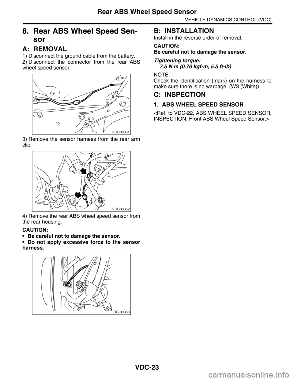
8. Rear ABS Wheel Speed Sen-
sor
A: REMOVAL
1) Disconnect the ground cable from the battery.
2) Disconnect the connector from the rear ABS
wheel speed sensor.
3) Remove the sensor harness from the rear arm
clip.
4) Remove the rear ABS wheel speed sensor from
the rear housing.
CAUTION:
•Be careful not to damage the sensor.
•Do not apply excessive force to the sensor
harness.
B: INSTALLATION
Install in the reverse order of removal.
CAUTION:
Be careful not to damage the sensor.
Tightening torque:
7.5 N·m (0.76 kgf-m, 5.5 ft-lb)
NOTE:
Check the identification (mark) on the harness to
make sure there is no warpage. (W3 (White))
C: INSPECTION
1. ABS WHEEL SPEED SENSOR
VDC00351
VDC00352
DS-00363
Page 1167 of 2453
EN(H6DO)(diag)-6
General Description
ENGINE (DIAGNOSTICS)
C: NOTE
1. GENERAL DESCRIPTION
•The on-board diagnostics (OBD) system detects
and indicates a fault in various inputs and outputs
of the complex electronic control. Malfunction indi-
cator light in the combination meter indicates oc-
currence of a fault or trouble.
•Further, against such a failure or sensors as may
disable the drive, the fail-safe function is provided
to ensure the minimal drivability.
•The OBD system incorporated with the vehicles
within this engine family complies with OBD-II Reg-
ulations. The OBD system monitors the compo-
nents and the system malfunction listed in Engine
Section which affects on emissions.
•When the system decides that a malfunction oc-
curs, malfunction indicator light illuminates. At the
same time of the malfunction indicator light illumi-
nation or blinking, a DTC and a freeze frame en-
gine conditions are stored into on-board computer.
•The OBD system stores freeze frame engine
condition data (engine load, engine coolant tem-
perature, fuel trim, engine speed and vehicle
speed, etc.) into on-board computer when it detects
a malfunction first.
•If the OBD system detects the various malfunc-
tions including the fault of fuel trim or misfire, the
OBD system first stores freeze frame engine condi-
tions about fuel trim or misfire.
•When the malfunction does not occur again for
three consecutive driving cycles, malfunction indi-
cator light is turned off, but DTC remains at on-
board computer.
•When troubleshooting the vehicle which com-
plies with OBD-II Regulations, connect the Subaru
Select Monitor or general scan tool to the vehicle.
2. ENGINE AND EMISSION CONTROL SYS-
TEM
•The Multipoint Fuel Injection (MFI) system is a
system that supplies the optimum air-fuel mixture
to the engine for all the various operating condi-
tions through the use of the latest electronic tech-
nology.
With this system fuel, which is pressurized at a con-
stant pressure, is injected into the intake air pas-
sage of the cylinder head. The injection quantity of
fuel is controlled by an intermittent injection system
where the electro-magnetic injection valve (fuel in-
jector) opens only for a short period of time, de-
pending on the quantity of air required for one cycle
of operation. In actual operation, the injection quan-
tity is determined by the duration of an electric
pulse applied to the fuel injector and this permits
simple, yet highly precise metering of the fuel.
•Further, all the operating conditions of the engine
are converted into electric signals, and this results
in additional features of the system, such as large
improved adaptability, easier addition of compen-
sating element etc.
The MFI system also has the following features:
•Reduced emission of harmful exhaust gases.
•Reduced in fuel consumption.
•Increased engine output.
•Superior acceleration and deceleration.
•Superior startability and warm-up perfor-
mance in cold weather since compensation is
made for coolant and intake air temperature.
Page 1177 of 2453
EN(H6DO)(diag)-16
Engine Control Module (ECM) I/O Signal
ENGINE (DIAGNOSTICS)
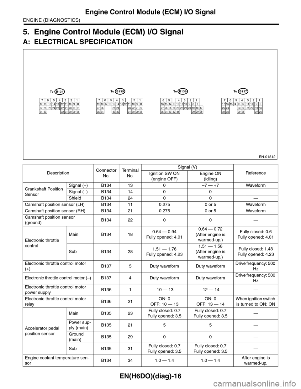
5. Engine Control Module (ECM) I/O Signal
A: ELECTRICAL SPECIFICATION
DescriptionConnector
No.
Te r m i n a l
No.
Signal (V)
ReferenceIgnition SW ON
(engine OFF)
Engine ON
(idling)
Crankshaft Position
Sensor
Signal (+) B134 13 0 –7 — +7 Waveform
Signal (–) B134 14 0 0 —
Shield B134 24 0 0 —
Camshaft position sensor (LH) B134 11 0.275 0 or 5 Waveform
Camshaft position sensor (RH) B134 21 0.275 0 or 5 Waveform
Camshaft position sensor
(ground)B134 22 0 0 —
Electronic throttle
control
Main B134 180.64 — 0.94
Fully opened: 4.01
0.64 — 0.72
(After engine is
warmed-up.)
Fully closed: 0.6
Fully opened: 4.01
Sub B134 281.51 — 1.76
Fully opened: 4.23
1.51 — 1.58
(After engine is
warmed-up.)
Fully closed: 1.48
Fully opened: 4.23
Electronic throttle control motor
(+)B137 5 Duty waveform Duty waveformDrive frequency: 500
Hz
Electronic throttle control motor (–) B137 4 Duty waveform Duty waveformDrive frequency: 500
Hz
Electronic throttle control motor
power supplyB136 1 10 — 13 12 — 14 —
Electronic throttle control motor
relayB136 21ON: 0
OFF: 10 — 13
ON: 0
OFF: 13 — 14
When ignition switch
is turned to ON: ON
Accelerator pedal
position sensor
Main B135 23Fully closed: 0.7
Fully opened: 3.5
Fully closed: 0.7
Fully opened: 3.5—
Powe r s up -
ply (main)B135 21 5 5 —
Ground
(main)B135 29 0 0 —
Sub B135 31Fully closed: 0.7
Fully opened: 3.5
Fully closed: 0.7
Fully opened: 3.5—
Engine coolant temperature sen-
sorB134 34 1.0 — 1.4 1.0 — 1.4After engine is
warmed-up.
EN-01812
B134
5678219431024 2223251112131415262728
1617181920213334 2932 3031
B136
5678219431024 2223251112131415262728
16171819202133342932303135
B135
5678219431024 2223251112131415262728
16171819202129303132333435
B137
5678219431022231112131415242526
1617181920212728293031
ToToToTo
Page 1180 of 2453
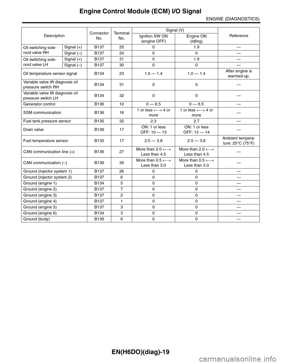
EN(H6DO)(diag)-19
Engine Control Module (ECM) I/O Signal
ENGINE (DIAGNOSTICS)
Oil switching sole-
noid valve RH
Signal (+) B137 25 0 1.9 —
Signal (–) B137 24 0 0 —
Oil switching sole-
noid valve LH
Signal (+) B137 31 0 1.9 —
Signal (–) B137 30 0 0 —
Oil temperature sensor signal B134 23 1.0 — 1.4 1.0 — 1.4After engine is
warmed-up.
Va r i a b l e va l v e l i f t d i a g n o s i s o i l
pressure switch RHB134 31 0 0 —
Va r i a b l e va l v e l i f t d i a g n o s i s o i l
pressure switch LHB134 32 0 0 —
Generator control B136 10 0 — 6.5 0 — 6.5 —
SSM communication B136 161 or less ←→ 4 or
more
1 or less ←→ 4 or
more—
Fuel tank pressure sensor B135 32 2.3 2.7 —
Drain valve B136 17ON: 1 or less
OFF: 10 — 13
ON: 1 or less
OFF: 13 — 14—
Fuel temperature sensor B135 17 2.5 — 3.8 2.5 — 3.8Ambient tempera-
ture: 25°C (75°F)
CAN communication line (+) B136 27More than 2.0 ←→
Less than 4.5
More than 2.0 ←→
Less than 4.5—
CAN communication (–) B136 35More than 0.5 ←→
Less than 3.0
More than 0.5 ←→
Less than 3.0—
Ground (injector system 1) B137 26 0 0 —
Ground (injector system 2) B137 6 0 0 —
Ground (engine 1) B134 5 0 0 —
Ground (engine 2) B137 7 0 0 —
Ground (engine 3) B137 2 0 0 —
Ground (engine 4) B137 1 0 0 —
Ground (engine 5) B137 3 0 0 —
Ground (engine 6) B134 3 0 0 —
Ground (body) B136 6 0 0 —
DescriptionConnector
No.
Te r m i n a l
No.
Signal (V)
ReferenceIgnition SW ON
(engine OFF)
Engine ON
(idling)
Page 1188 of 2453
![SUBARU TRIBECA 2009 1.G Service Workshop Manual EN(H6DO)(diag)-27
Subaru Select Monitor
ENGINE (DIAGNOSTICS)
4. READ CURRENT DATA FOR ENGINE (NORMAL MODE)
1) On the «Main Menu» display screen, select the {Each System Check} and press the [YES] ke SUBARU TRIBECA 2009 1.G Service Workshop Manual EN(H6DO)(diag)-27
Subaru Select Monitor
ENGINE (DIAGNOSTICS)
4. READ CURRENT DATA FOR ENGINE (NORMAL MODE)
1) On the «Main Menu» display screen, select the {Each System Check} and press the [YES] ke](/manual-img/17/7322/w960_7322-1187.png)
EN(H6DO)(diag)-27
Subaru Select Monitor
ENGINE (DIAGNOSTICS)
4. READ CURRENT DATA FOR ENGINE (NORMAL MODE)
1) On the «Main Menu» display screen, select the {Each System Check} and press the [YES] key.
2) On the «System Selection Menu» display screen, select the {Engine} and press the [YES] key.
3) Press the [YES] key after the information of engine type has been displayed.
4) On the «Engine Diagnosis» display screen, select the {Current Data Display/Save}, and then press the
[YES] key.
5) On the «Data Display Menu» screen, select the {Data Display} and press the [YES] key.
6) Using the scroll key, scroll the display screen up or down until the desired data is shown.
•A list of the support data is shown in the following table.
Description Display Unit of measure Note (at idling)
Engine load Engine load % 3.5%
Engine coolant temperature signal Coolant Temp. °C or °F≥ 75°C or 167°F (After
engine is warmed-up.)
A/F compensation 1 A/F Compensation 1 % 3.1%
A/F learning 1 A/F learning 1 % 0.0%
A/F compensation 2 A/F Compensation 2 % 4.7%
A/F learning 2 A/F learning 2 % 0.0%
Intake manifold absolute pressure Mani. Absolute PressuremmHg, kPa,
inHg or psig
200 — 300 mmHg, 26.7 —
40 kPa, 7.8 — 11.8 inHg or
3.8 — 5.8 psig
Engine speed signal Engine speed rpm 600 — 800 rpm
Meter vehicle speed signal Meter vehicle speed km/h or MPH 0 km/h or 0 MPH
Ignition timing signal Ignition timing deg 13 — 15 deg
Intake air temperature signal Intake air temperature °C or °F (Ambient air temperature)
Amount of intake air Mass Air Flow g/s or lb/m 3.8 g/s or 0.5 lb/m
Throttle opening angle signal Throttle valve angle % 1.2 — 1.6%
Fr o nt ox yg e n se n so r vo lt a g e val ue 1Fr o n t oxy ge n s en s or vol t ag e
value 1V0.035 V
Fr o nt ox yg e n se n so r vo lt a g e val ue 2Fr o n t oxy ge n s en s or vol t ag e
value 2V0.020 V
Battery voltage Battery Voltage V 12 — 14 V
Mass air flow voltage Mass air flow voltage V 1.1 — 1.2 V
Injection 1 pulse width Injection 1 pulse width ms 2.82 ms
Injection 2 pulse width Injection 2 pulse width ms 2.82 ms
Knock sensor compensation Knock correction deg 0 deg
Atmospheric pressure signal Atmospheric pressuremmHg, kPa,
inHg or psig(Atmospheric pressure)
Intake manifold relative pressureIntake manifold relative pres-
sure
mmHg, kPa,
inHg or psig
(Intake manifold absolute
pressure — atmospheric
pressure)
Acceleration opening angle signal Acceleration opening angle % 0%
Radiator fan output Radiator fan output % 0%
Purge control solenoid valve duty ratio CPC Duty % 0 — 3%
Generator duty ALT duty % 0%
Fuel pump duty Fuel pump duty % 33%
Va r i a b l e va l v e t i m i n g a d v a n c e a n g l e a m o u n t R V V T a d va n c e a n g l e a m o u n t R d e g 0 d e g
Va r i a b l e va l v e t i m i n g a d v a n c e a n g l e a m o u n t L V V T a d va n c e a n g l e a m o u n t L d e g 0 d e g
Oil flow control solenoid valve duty R OCV duty R % 9.4%
Oil flow control solenoid valve duty L OCV duty L % 9.4%
Oil flow control solenoid valve current R OCV current R mA 64 mA
Oil flow control solenoid valve current L OCV current L mA 64 mA
Fr o nt ox yg e n ( A / F) s en so r cu r r en t va l ue 1 A / F s en s or cu r r e nt va l ue 1 mA 0 . 0 m A
Fr o nt ox yg e n ( A / F) s en so r cu r r en t va l ue 2 A / F s en s or cu r r e nt va l ue 2 mA 0 . 0 m A
Fr o nt ox yg e n ( A / F) s en so r r es is t an ce val ue 1 A / F s en s or r e si st a nc e val u e 1Ω31 Ω
Page 1380 of 2453
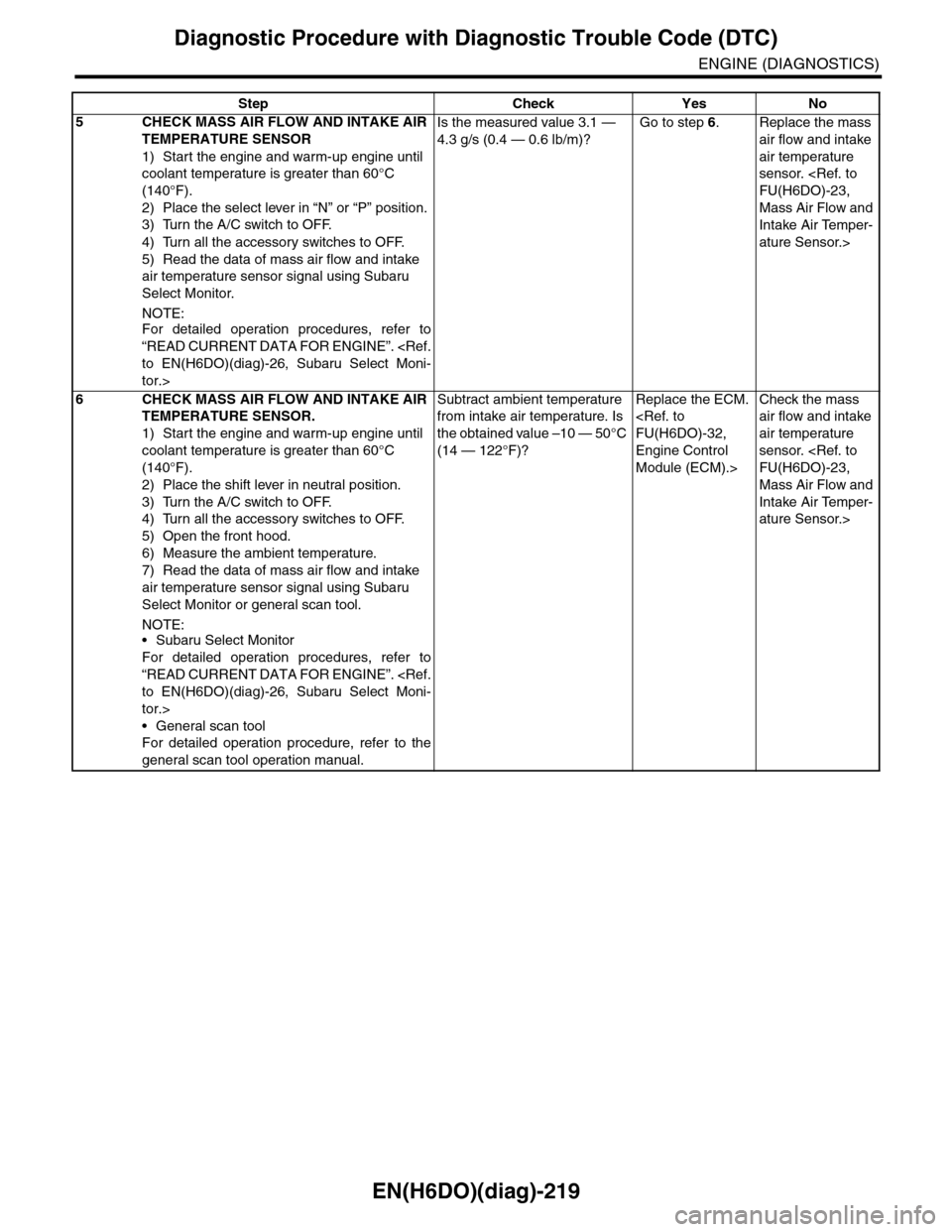
EN(H6DO)(diag)-219
Diagnostic Procedure with Diagnostic Trouble Code (DTC)
ENGINE (DIAGNOSTICS)
5CHECK MASS AIR FLOW AND INTAKE AIR
TEMPERATURE SENSOR
1) Start the engine and warm-up engine until
coolant temperature is greater than 60°C
(140°F).
2) Place the select lever in “N” or “P” position.
3) Turn the A/C switch to OFF.
4) Turn all the accessory switches to OFF.
5) Read the data of mass air flow and intake
air temperature sensor signal using Subaru
Select Monitor.
NOTE:
For detailed operation procedures, refer to
“READ CURRENT DATA FOR ENGINE”.
tor.>
Is the measured value 3.1 —
4.3 g/s (0.4 — 0.6 lb/m)?
Go to step 6.Replace the mass
air flow and intake
air temperature
sensor.
Mass Air Flow and
Intake Air Temper-
ature Sensor.>
6CHECK MASS AIR FLOW AND INTAKE AIR
TEMPERATURE SENSOR.
1) Start the engine and warm-up engine until
coolant temperature is greater than 60°C
(140°F).
2) Place the shift lever in neutral position.
3) Turn the A/C switch to OFF.
4) Turn all the accessory switches to OFF.
5) Open the front hood.
6) Measure the ambient temperature.
7) Read the data of mass air flow and intake
air temperature sensor signal using Subaru
Select Monitor or general scan tool.
NOTE:•Subaru Select Monitor
For detailed operation procedures, refer to
“READ CURRENT DATA FOR ENGINE”.
tor.>
•General scan tool
For detailed operation procedure, refer to the
general scan tool operation manual.
Subtract ambient temperature
from intake air temperature. Is
the obtained value –10 — 50°C
(14 — 122°F)?
Replace the ECM.
Engine Control
Module (ECM).>
Check the mass
air flow and intake
air temperature
sensor.
Mass Air Flow and
Intake Air Temper-
ature Sensor.>
Step Check Yes No
Page 1687 of 2453
GD(H6DO)-75
Diagnostic Trouble Code (DTC) Detecting Criteria
GENERAL DESCRIPTION
AQ:DTC P0139 O2 SENSOR CIRCUIT SLOW RESPONSE (BANK 1 SENSOR 2)
1. OUTLINE OF DIAGNOSIS
Detect the slow response of the oxygen sensor.
Judge as NG if either the rich to lean response diagnosis or lean to rich response diagnosis is NG, and Judge
as OK if both are OK.
[Rich → Lean diagnosis response]
1. Measure the response time for oxygen sensor output changes when the A/F ratio changes to rich to lean.
If the measured response time is larger than the threshold value, it is NG. If it is smaller, it is OK.
2. Judge as NG when the oxygen sensor voltage is large (rich) when recovering from a deceleration fuel cut.
[Lean → Rich diagnosis response]
1. Measure the response time for oxygen sensor output changes when the A/F ratio changes to lean to rich.
If the measured response time is larger than the threshold value, it is NG.
2. Judge as NG when the oxygen sensor voltage remains small when recovering from a deceleration fuel cut.
Diagnostic method
Measure the response time of the output change of the oxygen sensor when the A/F ratio changes to rich to
lean. And Judge as NG when the measured response time is larger than the threshold value.
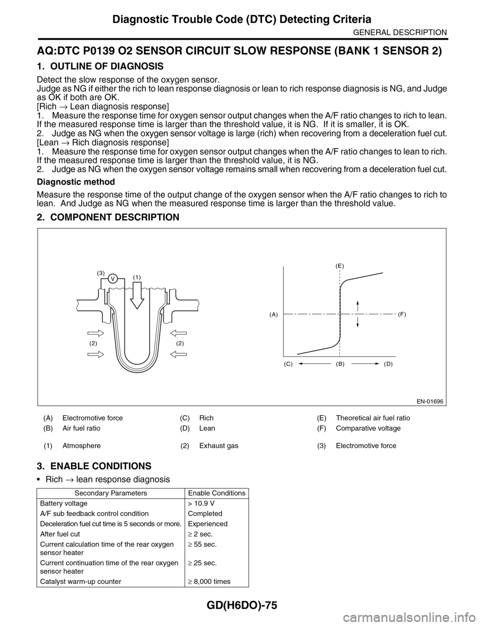
2. COMPONENT DESCRIPTION
3. ENABLE CONDITIONS
•Rich → lean response diagnosis
(A) Electromotive force (C) Rich (E) Theoretical air fuel ratio
(B) Air fuel ratio (D) Lean (F) Comparative voltage
(1) Atmosphere (2) Exhaust gas (3) Electromotive force
Secondary Parameters Enable Conditions
Battery voltage > 10.9 V
A/F sub feedback control condition Completed
Deceleration fuel cut time is 5 seconds or more. Experienced
After fuel cut≥ 2 sec.
Current calculation time of the rear oxygen
sensor heater
≥ 55 sec.
Current continuation time of the rear oxygen
sensor heater
≥ 25 sec.
Catalyst warm-up counter≥ 8,000 times
EN-01696
(3)V(1)
(2) (2)
(E)
(F)
(C) (B) (D)
(A)