Page 2298 of 2453

WI-14
Working Precautions
WIRING SYSTEM
2. Working Precautions
A: PRECAUTIONS WHEN WORKING
WITH THE PARTS MOUNTED ON
THE VEHICLE
1) When working under a vehicle which is jacked-
up, always be sure to use rigid rack.
2) The parking brake must always be applied dur-
ing working. Also, in automatic transmission vehi-
cles, keep the select lever set to the P (Parking)
range.
3) Be sure the workshop is properly ventilated
when running the engine. Further, be careful not to
touch the belt or fan while the engine is operating.
4) Be careful not to touch hot metal parts, especial-
ly the radiator and exhaust system immediately af-
ter the engine has been turned off.
B: PRECAUTIONS IN TROUBLE DI-
AGNOSIS AND REPAIR OF ELEC-
TRIC PARTS
1) The battery cable must be disconnected from
the battery’s (–) terminal, and the ignition switch
must be set to the OFF position, unless otherwise
required by the diagnostics.
2) Securely fasten the wiring harness with clamps
and slips so that the harness does not interfere with
the body end parts or edges and bolts or screws.
3) When installing parts, be careful not to catch
them on the wiring harness.
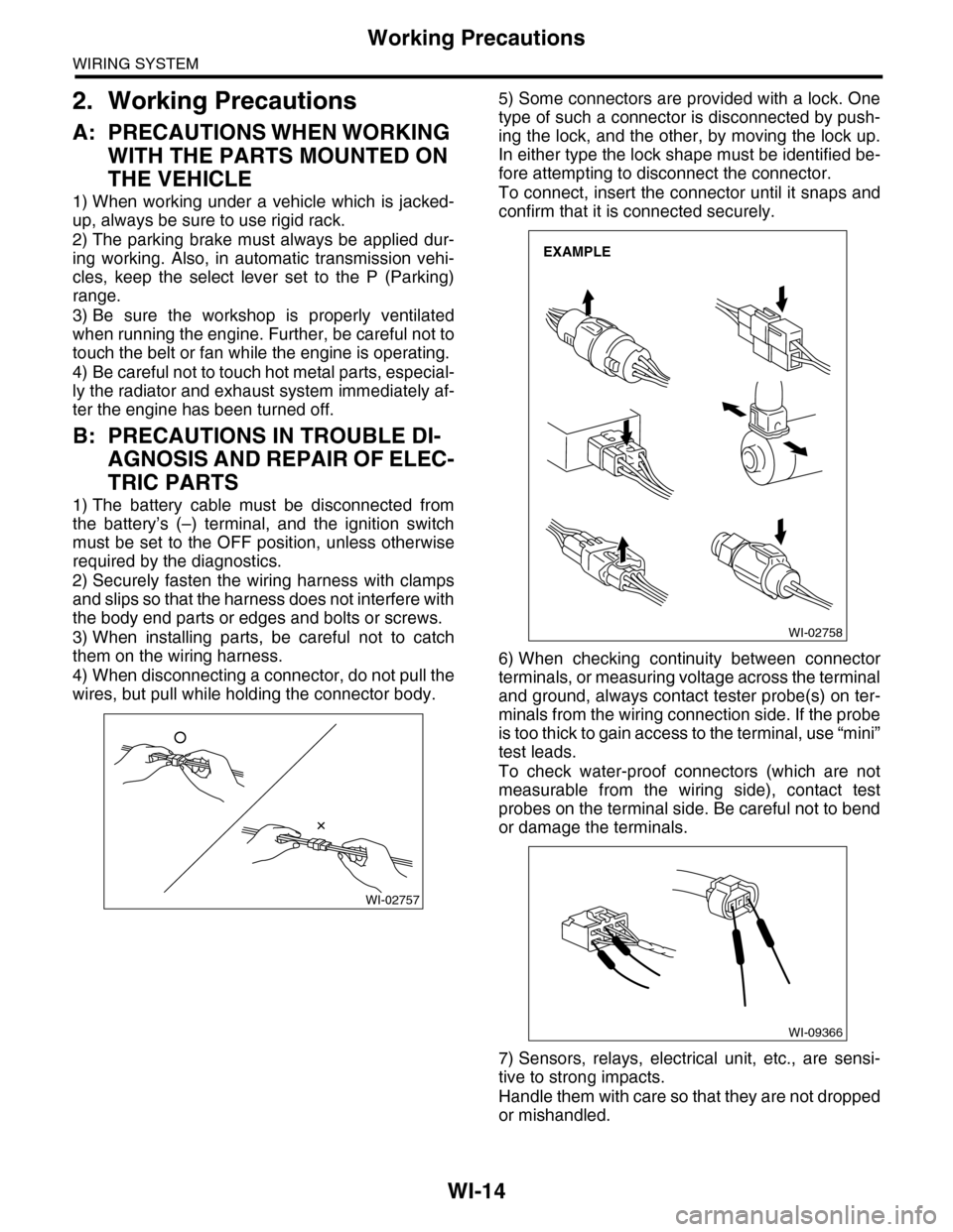
4) When disconnecting a connector, do not pull the
wires, but pull while holding the connector body.
5) Some connectors are provided with a lock. One
type of such a connector is disconnected by push-
ing the lock, and the other, by moving the lock up.
In either type the lock shape must be identified be-
fore attempting to disconnect the connector.
To connect, insert the connector until it snaps and
confirm that it is connected securely.
6) When checking continuity between connector
terminals, or measuring voltage across the terminal
and ground, always contact tester probe(s) on ter-
minals from the wiring connection side. If the probe
is too thick to gain access to the terminal, use “mini”
test leads.
To check water-proof connectors (which are not
measurable from the wiring side), contact test
probes on the terminal side. Be careful not to bend
or damage the terminals.
7) Sensors, relays, electrical unit, etc., are sensi-
tive to strong impacts.
Handle them with care so that they are not dropped
or mishandled.
WI-02757
WI-02758
EXAMPLE
WI-09366
Page 2299 of 2453
WI-15
Power Supply Circuit
WIRING SYSTEM
3. Power Supply Circuit
A: WIRING DIAGRAM
WI-08510
P-SUP-01P-SUP-01
MAIN FUSE BOX (M/B)
FUSE & RELAY BOX (F/B)
H/LRELAYRH
MAINFANRELAY-1
MAINSBFH/LRELAYLH
NO. 8
NO. 11
NO. 12
NO. 13
NO. 14
NO. 15
NO. 16
NO. 27
NO. 28
NO. 29
NO. 30
NO. 31
NO. 32
NO. 33
NO. 20
NO. 21
NO. 22
NO. 23
NO. 24
NO. 25
NO. 26
NO. 13
NO. 14
NO. 15
NO. 16
NO. 17
NO. 18
NO. 19
NO. 6
NO. 7
NO. 8
NO. 9
NO. 10
NO. 11
NO. 12
NO. 1
NO. 2
NO. 3
NO. 4
NO. 5
NO. 9
NO. 10
NO. 3
NO. 4
NO. 1
NO. 2
NO. 5
NO. 6
NO. 7
SBF-8
SBF-6SBF-2
SBF-3
SBF-4
SBF-7SBF-5
SBF-1
HORNRELAYR.DEFRELAY
TAILRELAY
Page 2300 of 2453
WI-16
Power Supply Circuit
WIRING SYSTEM
WI-08026
P-SUP-02P-SUP-02
WR
BR
WB21BR3
B14B7C10
GENERATOR
MAIN FUSE BOX(M/B)
BATTERY
MB-2
F26
MB-29MB-1MB-9MB-8MB-6
A7A9
A16
P-SUP-05B
P-SUP-05A
P-SUP-03C
NO. 4 25A
MAINSBF 120A
P-SUP-04I
P-SUP-04H
P-SUP-03D
NO. 2 25ANO. 8 20ANO. 3 25ANO. 5 20ANO. 1 30ANO. 16 7.5A
NO. 10 25A
SBF-1 50ASBF-8 50ASBF-6 50ASBF-3 50ASBF-2 50A
E5E6
RL
G7H8
GOrGB
WH4B19
ALT-1
B433B145G:
12
F26
123
B186H:(BROWN)B144D:(BLUE)F35C:
A:
12345678123456789101112
F37
F:
P-SUP-05G
P-SUP-05F
P-SUP-04E
MAIN FANRELAY 1
REAR DEFOGGER
RELAY
WW
F37A:
B143B:
F35C:
B144D:
F36E:
B433F:
B145G:
B186H:
LR
D9
G
D3
W
D2
R
D6E3D1
RY
D5
WR
D7B11
L
D8
MB-5
1234567
157628349
1234 5678910 11 12 13 14 15 16 17 18 19 20
B:B143
1234 5678910 11 12 13 14 15 16 17 18 19 20
CURRENT FROM IGNITIONSWITCH "IG" TERMINAL
OTHER CURRENT
BATTERY CURRENT
CURRENT FROM IGNITIONSWITCH "ACC" TERMINAL
GRLWLg
F36E:
(BROWN)
Page 2301 of 2453
WI-17
Power Supply Circuit
WIRING SYSTEM
WI-08027
P-SUP-03P-SUP-03
WB
H6
W
H5G4
MAIN FUSE BOX
P-SUP-05K
P-SUP-05J
NO. 14 15ANO. 13 7.5ANO. 12 15ANO. 11 15ANO. 15 20A
NO. 6 15A
SBF-4 30ASBF-7 30ASBF-5 30A
BWWG
H3
BR
G6H7
YRWY
G1G5F2F1
WL
BrBrR
B18B16
B145G:B186H:(BROWN)B144D:(BLUE)F35C:
123456781234567891011121234 567891011 12 13 1415 16 17 18 19 20
B:B143
NO. 7 15ANO. 9 15A
TAIL AND ILLUMINATION RELAY
F37A:
B143B:
F35C:
B144D:
F36E:
B433F:
B145G:
B186H:
RW
H1B6
RL
C8
RG
C9B15
RB
E1C1C2
R
G3H2
RB
B8
RG
E4
W
G2C11
1234567
157628349
P-SUP-02C
P-SUP-02D
MB-21MB-22MB-26MB-25MB-24MB-33MB-27MB-32MB-28MB-19MB-14MB-23MB-32
WGRW
MB-31MB-18MB-17MB-16MB-15MB-20MB-30
P-SUP-04N
P-SUP-04M
P-SUP-04L
HEADLIGHT RELAY RHHEADLIGHT RELAY LHHORN RELAY
LYBW
F36E:
A:F37
1234 5678910 11 12 13 14 15 16 17 18 19 20
(BROWN)B433
12
F:
Page 2302 of 2453
WI-18
Power Supply Circuit
WIRING SYSTEM
WI-08028
P-SUP-04P-SUP-04
BL
B4B12C17
NO. 3 15ANO. 1 20ANO. 8 20A
BL
1WOr
VV
B10
V
A11C5A13B2A7B6
RL
C2
GL
F1A4
LR
B13
LR
LBW
E6E4
R
F6
LR
E2
R
C21
WG
W
C20E8E7
B69B158E:
B52C:
B159F:B152D:B228A:i5
1234 5678910 11 12 13 14 15 16 17 18 19 20
B: R168
NO. 9 20ANO. 10 7.5ANO. 27 15ANO. 28 15ANO. 29 15ANO. 17 15ANO. 16 10ANO. 15 20ANO. 14 15A
WOr
D10
WG
A9
LW
C15
FB-3FB-4FB-5FB-6FB-7FB-8FB-9FB-11FB-10
LB
E3
WL
E1C23
157628349
P-SUP-03N
P-SUP-03M
P-SUP-02E
P-SUP-02H
P-SUP-03L
P-SUP-02I
FUSE &RELAY BOX(F/B)
i5A:
R168B:
B52C:
B152D:
B158E:
B159F:
PARKINGSWITCH
24
1
B69ON
OFF
TBP
Or
C4
OPCONNECTOR
FB-14FB-13FB-12FB-15FB-16
12341234785612345678910131415
123456789101112
1234 5678910 11 12 13 14 15 16 17 18 19 20
3412 8910 1112 13 14 15 16 17 18 19 20 21 22 23 24567
B228
(BROWN)
FB-1
L
Page 2303 of 2453

WI-19
Power Supply Circuit
WIRING SYSTEM
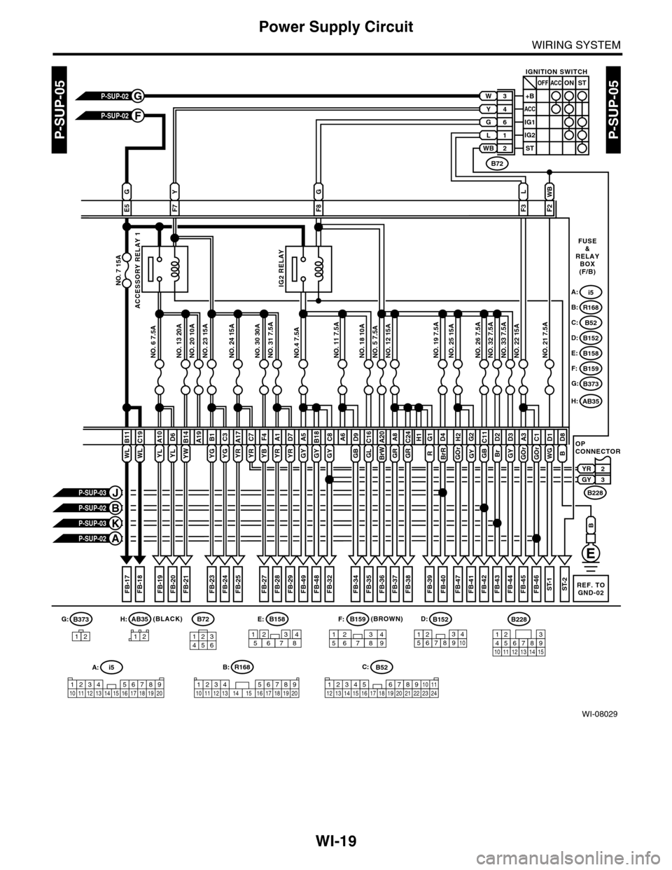
WI-08029
P-SUP-05P-SUP-05
WL
B11
NO. 7 15A
2YR3GY
R
G1D4
BrR
GY
E5F7
G
F8F3
NO. 20 10ANO. 23 15ANO. 24 15ANO. 30 30ANO. 31 7.5ANO.4 7.5ANO. 11 7.5ANO. 18 10ANO. 5 7.5ANO. 12 15ANO. 19 7.5ANO. 25 15ANO. 26 7.5ANO. 32 7.5ANO. 33 7.5ANO. 22 15ANO. 21 7.5ANO. 13 20ANO. 6 7.5A
A19
FB-17FB-18FB-19FB-21
A10
WL
C19
P-SUP-02G
P-SUP-02F
P-SUP-03K
P-SUP-02A
P-SUP-03J
P-SUP-02B
FUSE&RELAYBOX(F/B)
i5A:
R168B:
B52C:
B152D:
B158E:
B159F:
B373G:
L
F2
WB
OPCONNECTOR
FB-40FB-39
GB
C11D2
Br
G2
GY
H2
WG
D1
GOrGOr
A3D8
GY
D3C1
FB-41FB-42FB-43FB-44FB-45FB-46ST-1ST-2
B228
B72
IGNITION SWITCH
3+B
4
6
L
WB
1
2
ACC
ACCOFF
IG2
ST
ONST
IG1
W
G
Y
FB-20
D6
ACCESSORY RELAY 1
IG2 RELAY
FB-23FB-24FB-25FB-27FB-28FB-29FB-32FB-34FB-35FB-36FB-37FB-38
YL
B1
YG
C3
YG
A17
YR
C7
YR
F4
YB
A1
YR
D7
YR
A5B18
YW
B14
YLGY
C8A6
GB
D9C16
GLBrW
A20
GR
A8
GR
C24H1
B
B
B373B158E:G:
B52C:
B159F:B152D:B228
A:i5
1234 5678910 11 12 13 14 15 16 17 18 19 20
1576283491234785612345678910131415
123456789101112
3412 8910 1112 13 14 15 16 17 18 19 20 21 22 23 24567
12
B:R168
12345678910 11 12 13 14 15 16 17 18 19 20
B72
134562
REF. TOGND-02
(BROWN)
AB35H:
FB-48FB-49
GYGYGOr
FB-47
12
AB35H:(BLACK)
Page 2304 of 2453

WI-20
Power Supply Circuit
WIRING SYSTEM
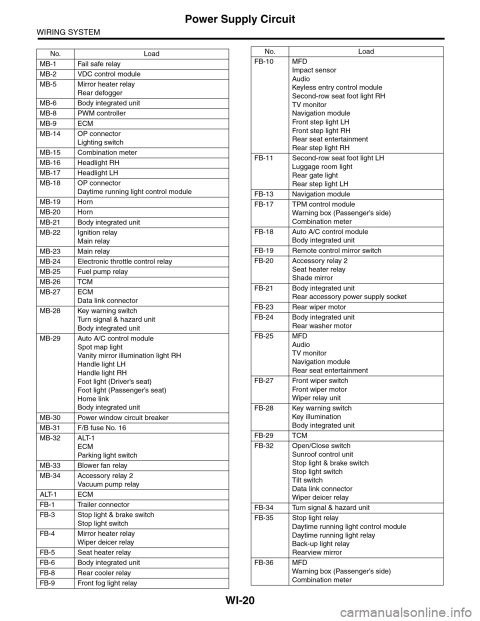
No. Load
MB-1 Fail safe relay
MB-2 VDC control module
MB-5 Mirror heater relay
Rear defogger
MB-6 Body integrated unit
MB-8 PWM controller
MB-9 ECM
MB-14 OP connector
Lighting switch
MB-15 Combination meter
MB-16 Headlight RH
MB-17 Headlight LH
MB-18 OP connector
Daytime running light control module
MB-19 Horn
MB-20 Horn
MB-21 Body integrated unit
MB-22 Ignition relay
Main relay
MB-23 Main relay
MB-24 Electronic throttle control relay
MB-25 Fuel pump relay
MB-26 TCM
MB-27 ECM
Data link connector
MB-28 Key warning switch
Tu r n s i g n a l & h a z a r d u n i t
Body integrated unit
MB-29 Auto A/C control module
Spot map light
Va n i t y m i r r o r i l l u m i n a t i o n l i g h t R H
Handle light LH
Handle light RH
Foot light (Driver’s seat)
Foot light (Passenger’s seat)
Home link
Body integrated unit
MB-30 Power window circuit breaker
MB-31 F/B fuse No. 16
MB-32 ALT-1
ECM
Par king light switch
MB-33 Blower fan relay
MB-34 Accessory relay 2
Va c u u m p u m p r e l ay
ALT-1 ECM
FB-1 Trailer connector
FB-3 Stop light & brake switch
Stop light switch
FB-4 Mirror heater relay
Wiper deicer relay
FB-5 Seat heater relay
FB-6 Body integrated unit
FB-8 Rear cooler relay
FB-9 Front fog light relay
FB-10 MFD
Impact sensor
Audio
Keyless entr y control module
Second-row seat foot light RH
TV monitor
Navigation module
Fr o n t s te p li gh t LH
Fr o n t s te p li gh t RH
Rear seat entertainment
Rear step light RH
FB-11 Second-row seat foot light LH
Luggage room light
Rear gate light
Rear step light LH
FB-13 Navigation module
FB-17 TPM control module
War ning box (Passenger’s side)
Combination meter
FB-18 Auto A/C control module
Body integrated unit
FB-19 Remote control mirror switch
FB-20 Accessory relay 2
Seat heater relay
Shade mirror
FB-21 Body integrated unit
Rear accessory power supply socket
FB-23 Rear wiper motor
FB-24 Body integrated unit
Rear washer motor
FB-25 MFD
Audio
TV monitor
Navigation module
Rear seat entertainment
FB-27 Front wiper switch
Fr o n t wi p er mo t or
Wiper relay unit
FB-28 Key warning switch
Key illumination
Body integrated unit
FB-29 TCM
FB-32 Open/Close switch
Sunroof control unit
Stop light & brake switch
Stop light switch
Tilt switch
Data link connector
Wiper deicer relay
FB-34 Turn signal & hazard unit
FB-35 Stop light relay
Daytime running light control module
Daytime running light relay
Back-up light relay
Rearview mirror
FB-36 MFD
War ning box (Passenger’s side)
Combination meter
No. Load
Page 2305 of 2453
WI-21
Power Supply Circuit
WIRING SYSTEM
FB-37 Body integrated unit
FB-38 ECM
TCM
Fuel pump relay
FB-39 Airbag control module
FB-41 Airbag control module
FB-42 Power window relay
FB-44 VDC control module
Steering angle sensor
Ya w r a t e s e n s o r
FB-45 A/C control panel
Rear cooler relay
FB-46 A/C relay
FRESH/RECIRC actuator
Auto A/C control module
Pressure switch
Blower fan relay
FB-47 Occupant detection control module
FB-48 TPM control module
FB-49 Impact sensor
TV monitor
ACC -1 Front washer motor
ST-1 ECM
Starter relay
No. Load