2009 SUBARU TRIBECA relay
[x] Cancel search: relayPage 2210 of 2453
5AT(diag)-93
Diagnostic Procedure with Diagnostic Trouble Code (DTC)
AUTOMATIC TRANSMISSION (DIAGNOSTICS)
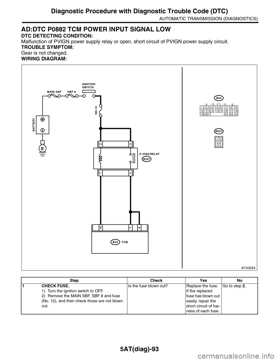
AD:DTC P0882 TCM POWER INPUT SIGNAL LOW
DTC DETECTING CONDITION:
Malfunction of PVIGN power supply relay or open, short circuit of PVIGN power supply circuit.
TROUBLE SYMPTOM:
Gear is not changed.
WIRING DIAGRAM:
AT-03294
8710
B54
B357
TCM
B54
B357
12789563410 11 1219 20 2113 14 15 16 17 18222324
MAIN SBF SBF-8
NO.12
E
32
41
1234
BATTERY
IGNITIONSWITCH
1234
1234
RELAYP-VING
Step Check Yes No
1CHECK FUSE.
1) Turn the ignition switch to OFF.
2) Remove the MAIN SBF, SBF 8 and fuse
(No. 12), and then check those are not blown
out.
Is the fuse blown out? Replace the fuse.
If the replaced
fuse has blown out
easily, repair the
short circuit of har-
ness of each fuse.
Go to step 2.
Page 2211 of 2453
5AT(diag)-94
Diagnostic Procedure with Diagnostic Trouble Code (DTC)
AUTOMATIC TRANSMISSION (DIAGNOSTICS)
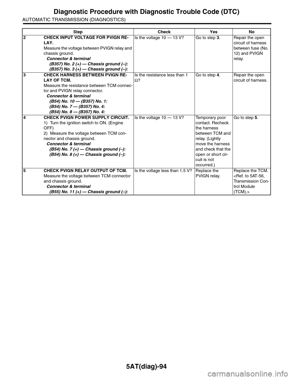
2CHECK INPUT VOLTAGE FOR PVIGN RE-
LAY.
Measure the voltage between PVIGN relay and
chassis ground.
Connector & terminal
(B357) No. 2 (+) — Chassis ground (–):
(B357) No. 3 (+) — Chassis ground (–):
Is the voltage 10 — 13 V? Go to step 3.Repair the open
circuit of harness
between fuse (No.
12) and PVIGN
relay.
3CHECK HARNESS BETWEEN PVIGN RE-
LAY OF TCM.
Measure the resistance between TCM connec-
tor and PVIGN relay connector.
Connector & terminal
(B54) No. 10 — (B357) No. 1:
(B54) No. 7 — (B357) No. 4:
(B54) No. 8 — (B357) No. 4:
Is the resistance less than 1
Ω?
Go to step 4.Repair the open
circuit of harness.
4CHECK PVIGN POWER SUPPLY CIRCUIT.
1) Turn the ignition switch to ON. (Engine
OFF)
2) Measure the voltage between TCM con-
nector and chassis ground.
Connector & terminal
(B54) No. 7 (+) — Chassis ground (–):
(B54) No. 8 (+) — Chassis ground (–):
Is the voltage 10 — 13 V? Temporary poor
contact. Recheck
the harness
between TCM and
relay. (Lightly
move the harness
and check that the
open or short cir-
cuit is not
occurred.)
Go to step 5.
5CHECK PVIGN RELAY OUTPUT OF TCM.
Measure the voltage between TCM connector
and chassis ground.
Connector & terminal
(B55) No. 11 (+) — Chassis ground (–):
Is the voltage less than 1.5 V? Replace the
PVIGN relay.
Replace the TCM.
trol Module
(TCM).>
Step Check Yes No
Page 2212 of 2453
5AT(diag)-95
Diagnostic Procedure with Diagnostic Trouble Code (DTC)
AUTOMATIC TRANSMISSION (DIAGNOSTICS)
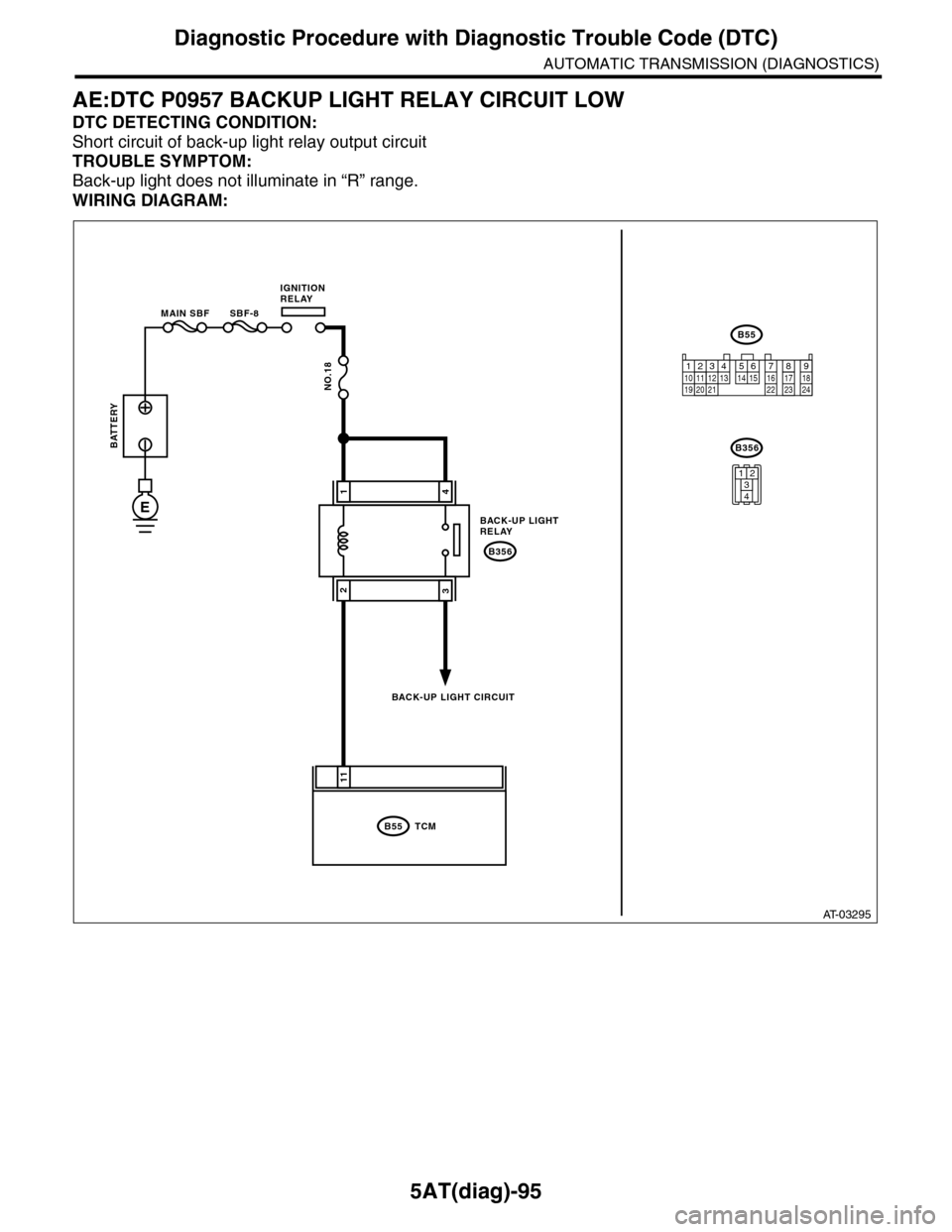
AE:DTC P0957 BACKUP LIGHT RELAY CIRCUIT LOW
DTC DETECTING CONDITION:
Short circuit of back-up light relay output circuit
TROUBLE SYMPTOM:
Back-up light does not illuminate in “R” range.
WIRING DIAGRAM:
AT-03295
11
B55
B356
TCM
B55
BATTERY
MAIN SBF SBF-8
IGNITIONRELAY
BACK-UP LIGHT CIRCUIT
NO.18
E
41
32
12341011 121920 21135614 1578916 17 1822 23 24
B356
1234
BACK-UP LIGHTRELAY
Page 2213 of 2453
5AT(diag)-96
Diagnostic Procedure with Diagnostic Trouble Code (DTC)
AUTOMATIC TRANSMISSION (DIAGNOSTICS)
Step Check Yes No
1CHECK DTC OF TCM.Is DTC of Transmission Range
Sensor Circuit (PRNDL Input)
detected?
Pe r for m t h e d ia g -
nosis according to
DTC.
Go to step 2.
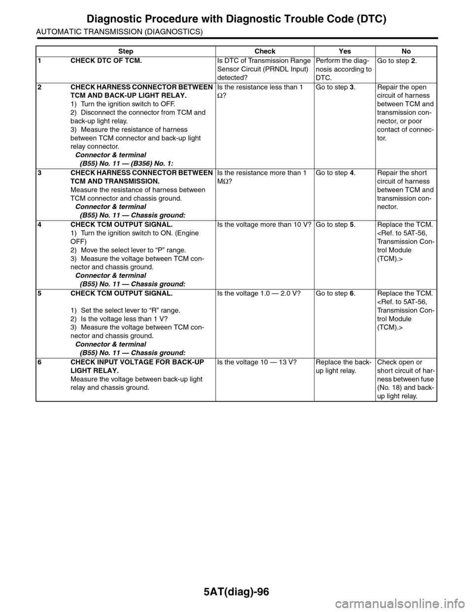
2CHECK HARNESS CONNECTOR BETWEEN
TCM AND BACK-UP LIGHT RELAY.
1) Turn the ignition switch to OFF.
2) Disconnect the connector from TCM and
back-up light relay.
3) Measure the resistance of harness
between TCM connector and back-up light
relay connector.
Connector & terminal
(B55) No. 11 — (B356) No. 1:
Is the resistance less than 1
Ω?
Go to step 3.Repair the open
circuit of harness
between TCM and
transmission con-
nector, or poor
contact of connec-
tor.
3CHECK HARNESS CONNECTOR BETWEEN
TCM AND TRANSMISSION.
Measure the resistance of harness between
TCM connector and chassis ground.
Connector & terminal
(B55) No. 11 — Chassis ground:
Is the resistance more than 1
MΩ?
Go to step 4.Repair the short
circuit of harness
between TCM and
transmission con-
nector.
4CHECK TCM OUTPUT SIGNAL.
1) Turn the ignition switch to ON. (Engine
OFF)
2) Move the select lever to “P” range.
3) Measure the voltage between TCM con-
nector and chassis ground.
Connector & terminal
(B55) No. 11 — Chassis ground:
Is the voltage more than 10 V? Go to step 5.Replace the TCM.
trol Module
(TCM).>
5CHECK TCM OUTPUT SIGNAL.
1) Set the select lever to “R” range.
2) Is the voltage less than 1 V?
3) Measure the voltage between TCM con-
nector and chassis ground.
Connector & terminal
(B55) No. 11 — Chassis ground:
Is the voltage 1.0 — 2.0 V? Go to step 6.Replace the TCM.
trol Module
(TCM).>
6CHECK INPUT VOLTAGE FOR BACK-UP
LIGHT RELAY.
Measure the voltage between back-up light
relay and chassis ground.
Is the voltage 10 — 13 V? Replace the back-
up light relay.
Check open or
short circuit of har-
ness between fuse
(No. 18) and back-
up light relay.
Page 2214 of 2453
5AT(diag)-97
Diagnostic Procedure with Diagnostic Trouble Code (DTC)
AUTOMATIC TRANSMISSION (DIAGNOSTICS)
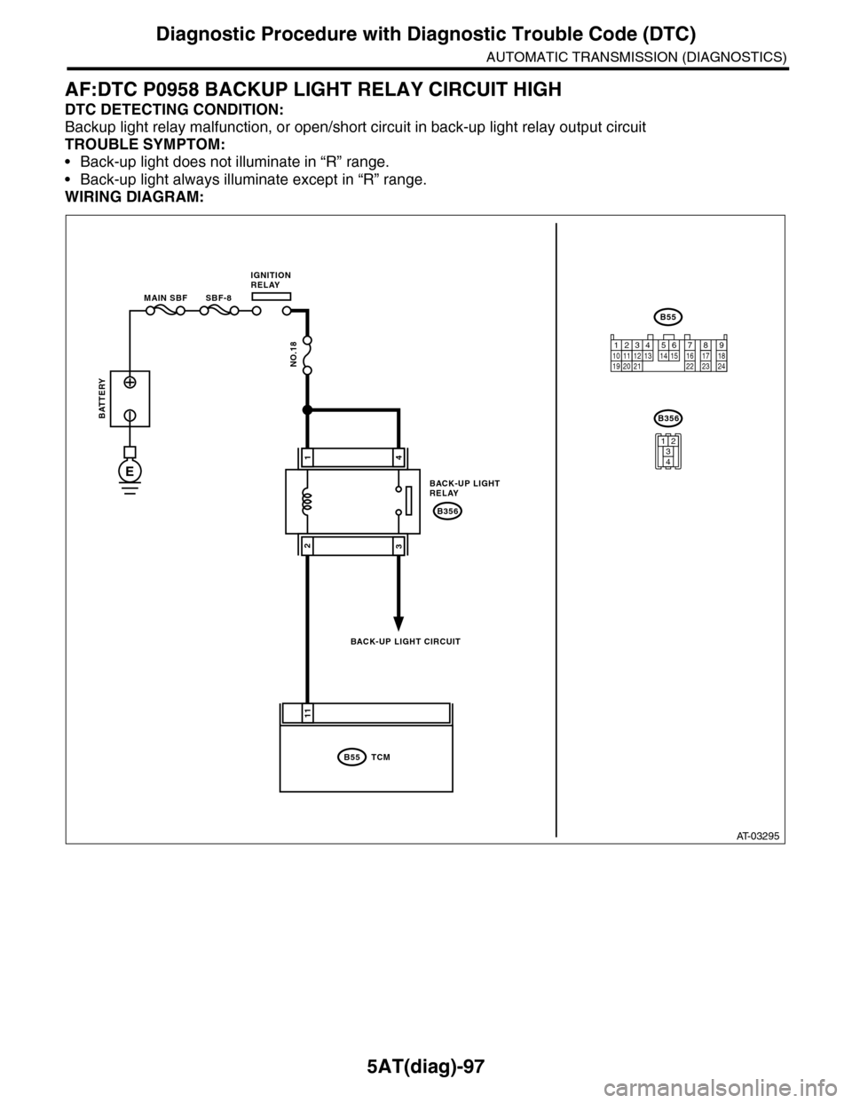
AF:DTC P0958 BACKUP LIGHT RELAY CIRCUIT HIGH
DTC DETECTING CONDITION:
Backup light relay malfunction, or open/short circuit in back-up light relay output circuit
TROUBLE SYMPTOM:
•Back-up light does not illuminate in “R” range.
•Back-up light always illuminate except in “R” range.
WIRING DIAGRAM:
AT-03295
11
B55
B356
TCM
B55
BATTERY
MAIN SBF SBF-8
IGNITIONRELAY
BACK-UP LIGHT CIRCUIT
NO.18
E
41
32
12341011 121920 21135614 1578916 17 1822 23 24
B356
1234
BACK-UP LIGHTRELAY
Page 2215 of 2453
5AT(diag)-98
Diagnostic Procedure with Diagnostic Trouble Code (DTC)
AUTOMATIC TRANSMISSION (DIAGNOSTICS)
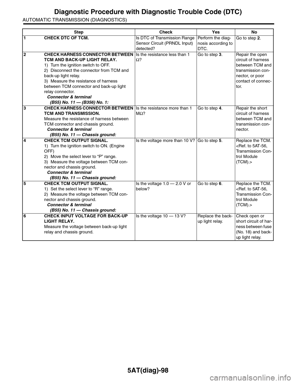
Step Check Yes No
1CHECK DTC OF TCM.Is DTC of Transmission Range
Sensor Circuit (PRNDL Input)
detected?
Pe r for m t h e d ia g -
nosis according to
DTC.
Go to step 2.
2CHECK HARNESS CONNECTOR BETWEEN
TCM AND BACK-UP LIGHT RELAY.
1) Turn the ignition switch to OFF.
2) Disconnect the connector from TCM and
back-up light relay.
3) Measure the resistance of harness
between TCM connector and back-up light
relay connector.
Connector & terminal
(B55) No. 11 — (B356) No. 1:
Is the resistance less than 1
Ω?
Go to step 3.Repair the open
circuit of harness
between TCM and
transmission con-
nector, or poor
contact of connec-
tor.
3CHECK HARNESS CONNECTOR BETWEEN
TCM AND TRANSMISSION.
Measure the resistance of harness between
TCM connector and chassis ground.
Connector & terminal
(B55) No. 11 — Chassis ground:
Is the resistance more than 1
MΩ?
Go to step 4.Repair the short
circuit of harness
between TCM and
transmission con-
nector.
4CHECK TCM OUTPUT SIGNAL.
1) Turn the ignition switch to ON. (Engine
OFF)
2) Move the select lever to “P” range.
3) Measure the voltage between TCM con-
nector and chassis ground.
Connector & terminal
(B55) No. 11 — Chassis ground:
Is the voltage more than 10 V? Go to step 5.Replace the TCM.
trol Module
(TCM).>
5CHECK TCM OUTPUT SIGNAL.
1) Set the select lever to “R” range.
2) Measure the voltage between TCM con-
nector and chassis ground.
Connector & terminal
(B55) No. 11 — Chassis ground:
Is the voltage 1.0 — 2.0 V or
below?
Go to step 6.Replace the TCM.
trol Module
(TCM).>
6CHECK INPUT VOLTAGE FOR BACK-UP
LIGHT RELAY.
Measure the voltage between back-up light
relay and chassis ground.
Is the voltage 10 — 13 V? Replace the back-
up light relay.
Check open or
short circuit of har-
ness between fuse
(No. 18) and back-
up light relay.
Page 2219 of 2453
5AT(diag)-102
Diagnostic Procedure with Diagnostic Trouble Code (DTC)
AUTOMATIC TRANSMISSION (DIAGNOSTICS)
Step Check Yes No
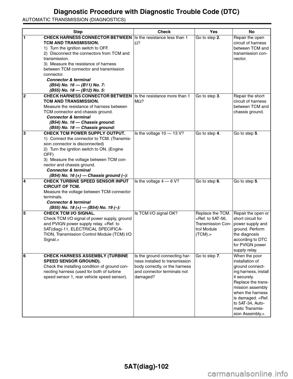
1CHECK HARNESS CONNECTOR BETWEEN
TCM AND TRANSMISSION.
1) Turn the ignition switch to OFF.
2) Disconnect the connectors from TCM and
transmission.
3) Measure the resistance of harness
between TCM connector and transmission
connector.
Connector & terminal
(B54) No. 16 — (B11) No. 7:
(B55) No. 18 — (B12) No. 5:
Is the resistance less than 1
Ω?
Go to step 2.Repair the open
circuit of harness
between TCM and
transmission con-
nector.
2CHECK HARNESS CONNECTOR BETWEEN
TCM AND TRANSMISSION.
Measure the resistance of harness between
TCM connector and chassis ground.
Connector & terminal
(B54) No. 16 — Chassis ground:
(B55) No. 18 — Chassis ground:
Is the resistance more than 1
MΩ?
Go to step 3.Repair the short
circuit of harness
between TCM and
chassis ground.
3CHECK TCM POWER SUPPLY OUTPUT.
1) Connect the connector to TCM. (Transmis-
sion connector is disconnected)
2) Turn the ignition switch to ON. (Engine
OFF)
3) Measure the voltage between TCM con-
nector and chassis ground.
Connector & terminal
(B54) No. 16 (+) — Chassis ground (–):
Is the voltage 10 — 13 V? Go to step 4.Go to step 5.
4CHECK TURBINE SPEED SENSOR INPUT
CIRCUIT OF TCM.
Measure the voltage between TCM connector
terminals.
Connector & terminal
(B55) No. 18 (+) — (B54) No. 19 (–):
Is the voltage 4 — 6 V? Go to step 6.Go to step 5.
5CHECK TCM I/O SIGNAL.
Check TCM I/O signal of power supply, ground
and PVIGN power supply relay.
TION, Transmission Control Module (TCM) I/O
Signal.>
Is TCM I/O signal OK? Replace the TCM.
trol Module
(TCM).>
Repair the open or
short circuit for
power supply and
ground. Perform
the diagnosis
according to DTC
for PVIGN power
supply relay.
6CHECK HARNESS ASSEMBLY (TURBINE
SPEED SENSOR GROUND).
Check the installing condition of ground con-
necting harness (used for both of turbine
speed sensor 1, rear vehicle speed sensor).
Is the ground connecting har-
ness installed to transmission
body correctly, or the harness
and connector terminals not
damaged?
Go to step 7.When the poor
installation of
ground connect-
ing harness, install
it securely.
Replace the trans-
mission assembly
when the harness
is damaged.
matic Transmis-
sion Assembly.>
Page 2225 of 2453
5AT(diag)-108
Diagnostic Procedure with Diagnostic Trouble Code (DTC)
AUTOMATIC TRANSMISSION (DIAGNOSTICS)
Step Check Yes No
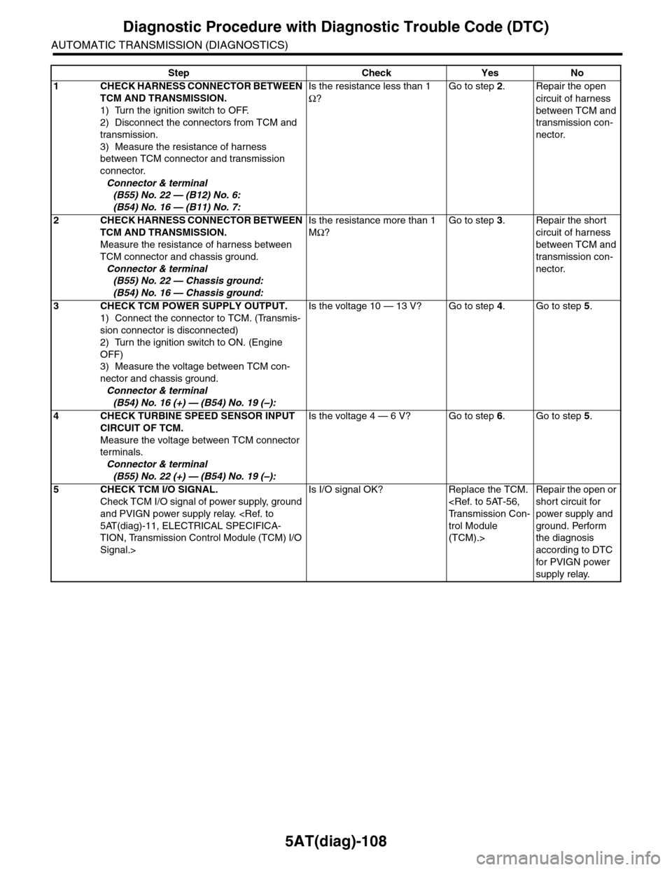
1CHECK HARNESS CONNECTOR BETWEEN
TCM AND TRANSMISSION.
1) Turn the ignition switch to OFF.
2) Disconnect the connectors from TCM and
transmission.
3) Measure the resistance of harness
between TCM connector and transmission
connector.
Connector & terminal
(B55) No. 22 — (B12) No. 6:
(B54) No. 16 — (B11) No. 7:
Is the resistance less than 1
Ω?
Go to step 2.Repair the open
circuit of harness
between TCM and
transmission con-
nector.
2CHECK HARNESS CONNECTOR BETWEEN
TCM AND TRANSMISSION.
Measure the resistance of harness between
TCM connector and chassis ground.
Connector & terminal
(B55) No. 22 — Chassis ground:
(B54) No. 16 — Chassis ground:
Is the resistance more than 1
MΩ?
Go to step 3.Repair the short
circuit of harness
between TCM and
transmission con-
nector.
3CHECK TCM POWER SUPPLY OUTPUT.
1) Connect the connector to TCM. (Transmis-
sion connector is disconnected)
2) Turn the ignition switch to ON. (Engine
OFF)
3) Measure the voltage between TCM con-
nector and chassis ground.
Connector & terminal
(B54) No. 16 (+) — (B54) No. 19 (–):
Is the voltage 10 — 13 V? Go to step 4.Go to step 5.
4CHECK TURBINE SPEED SENSOR INPUT
CIRCUIT OF TCM.
Measure the voltage between TCM connector
terminals.
Connector & terminal
(B55) No. 22 (+) — (B54) No. 19 (–):
Is the voltage 4 — 6 V? Go to step 6.Go to step 5.
5CHECK TCM I/O SIGNAL.
Check TCM I/O signal of power supply, ground
and PVIGN power supply relay.
TION, Transmission Control Module (TCM) I/O
Signal.>
Is I/O signal OK? Replace the TCM.
trol Module
(TCM).>
Repair the open or
short circuit for
power supply and
ground. Perform
the diagnosis
according to DTC
for PVIGN power
supply relay.