2009 SUBARU TRIBECA relay
[x] Cancel search: relayPage 1950 of 2453
ME(H6DO)-84
Engine Trouble in General
MECHANICAL
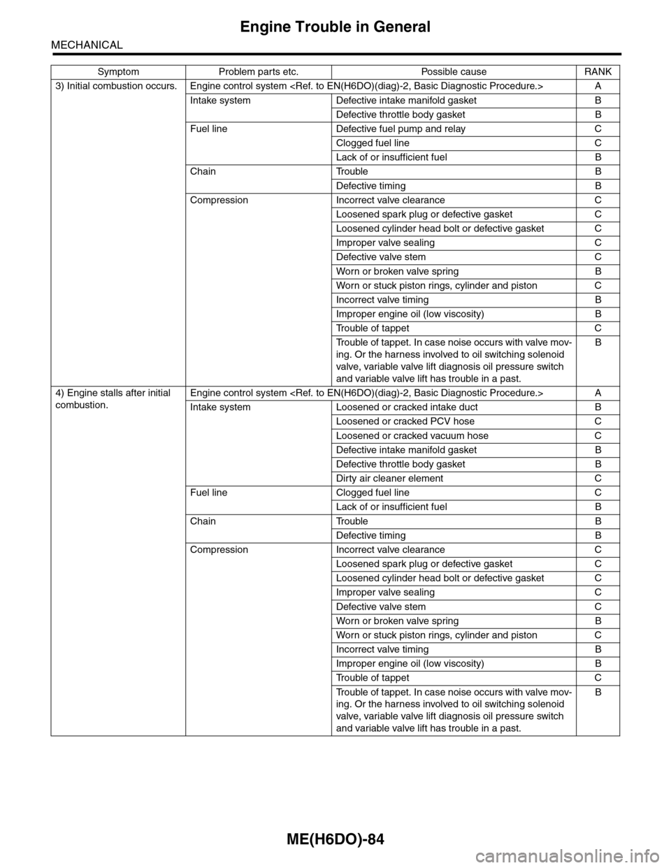
3) Initial combustion occurs. Engine control system
Intake system Defective intake manifold gasket B
Defective throttle body gasket B
Fuel line Defective fuel pump and relay C
Clogged fuel line C
Lack of or insufficient fuel B
Chain Trouble B
Defective timing B
Compression Incorrect valve clearance C
Loosened spark plug or defective gasket C
Loosened cylinder head bolt or defective gasket C
Improper valve sealing C
Defective valve stem C
Wor n or broken valve spr ing B
Wor n or stuck piston r ings, cylinder and piston C
Incorrect valve timing B
Improper engine oil (low viscosity) B
Tr o u b l e o f t a p p e t C
Tr o u b l e o f t a p p e t . I n c a s e n o i s e o c c u r s w i t h v a l v e m o v -
ing. Or the harness involved to oil switching solenoid
valve, variable valve lift diagnosis oil pressure switch
and variable valve lift has trouble in a past.
B
4) Engine stalls after initial
combustion.
Engine control system
Intake system Loosened or cracked intake duct B
Loosened or cracked PCV hose C
Loosened or cracked vacuum hose C
Defective intake manifold gasket B
Defective throttle body gasket B
Dirty air cleaner element C
Fuel line Clogged fuel line C
Lack of or insufficient fuel B
Chain Trouble B
Defective timing B
Compression Incorrect valve clearance C
Loosened spark plug or defective gasket C
Loosened cylinder head bolt or defective gasket C
Improper valve sealing C
Defective valve stem C
Wor n or broken valve spr ing B
Wor n or stuck piston r ings, cylinder and piston C
Incorrect valve timing B
Improper engine oil (low viscosity) B
Tr o u b l e o f t a p p e t C
Tr o u b l e o f t a p p e t . I n c a s e n o i s e o c c u r s w i t h v a l v e m o v -
ing. Or the harness involved to oil switching solenoid
valve, variable valve lift diagnosis oil pressure switch
and variable valve lift has trouble in a past.
B
Symptom Problem parts etc. Possible cause RANK
Page 1951 of 2453
ME(H6DO)-85
Engine Trouble in General
MECHANICAL
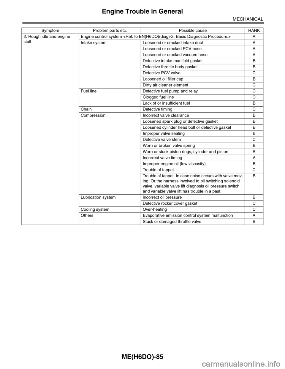
2. Rough idle and engine
stall
Engine control system
Intake system Loosened or cracked intake duct A
Loosened or cracked PCV hose A
Loosened or cracked vacuum hose A
Defective intake manifold gasket B
Defective throttle body gasket B
Defective PCV valve C
Loosened oil filler cap B
Dirty air cleaner element C
Fuel line Defective fuel pump and relay C
Clogged fuel line C
Lack of or insufficient fuel B
Chain Defective timing C
Compression Incorrect valve clearance B
Loosened spark plug or defective gasket B
Loosened cylinder head bolt or defective gasket B
Improper valve sealing B
Defective valve stem C
Wor n or broken valve spr ing B
Wor n or stuck piston r ings, cylinder and piston B
Incorrect valve timing A
Improper engine oil (low viscosity) B
Tr o u b l e o f t a p p e t C
Tr o u b l e o f t a p p e t . I n c a s e n o i s e o c c u r s w i t h v a l v e m o v -
ing. Or the harness involved to oil switching solenoid
valve, variable valve lift diagnosis oil pressure switch
and variable valve lift has trouble in a past.
B
Lubrication system Incorrect oil pressure B
Defective rocker cover gasket C
Cooling system Over-heating C
Others Evaporative emission control system malfunction A
Stuck or damaged throttle valve B
Symptom Problem parts etc. Possible cause RANK
Page 1952 of 2453
ME(H6DO)-86
Engine Trouble in General
MECHANICAL
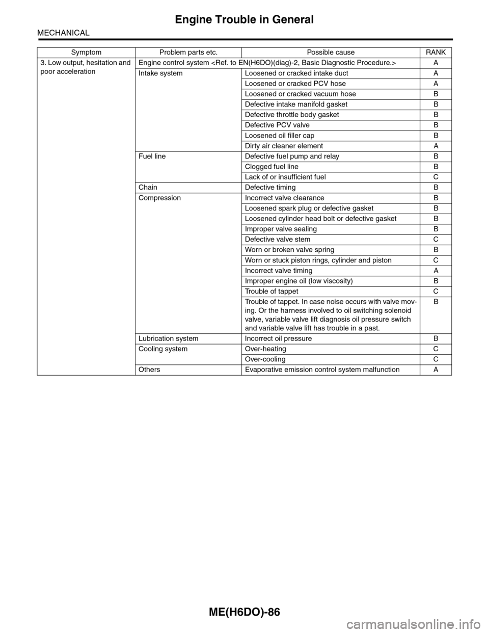
3. Low output, hesitation and
poor acceleration
Engine control system
Intake system Loosened or cracked intake duct A
Loosened or cracked PCV hose A
Loosened or cracked vacuum hose B
Defective intake manifold gasket B
Defective throttle body gasket B
Defective PCV valve B
Loosened oil filler cap B
Dirty air cleaner element A
Fuel line Defective fuel pump and relay B
Clogged fuel line B
Lack of or insufficient fuel C
Chain Defective timing B
Compression Incorrect valve clearance B
Loosened spark plug or defective gasket B
Loosened cylinder head bolt or defective gasket B
Improper valve sealing B
Defective valve stem C
Wor n or broken valve spr ing B
Wor n or stuck piston r ings, cylinder and piston C
Incorrect valve timing A
Improper engine oil (low viscosity) B
Tr o u b l e o f t a p p e t C
Tr o u b l e o f t a p p e t . I n c a s e n o i s e o c c u r s w i t h v a l v e m o v -
ing. Or the harness involved to oil switching solenoid
valve, variable valve lift diagnosis oil pressure switch
and variable valve lift has trouble in a past.
B
Lubrication system Incorrect oil pressure B
Cooling system Over-heating C
Over-cooling C
Others Evaporative emission control system malfunction A
Symptom Problem parts etc. Possible cause RANK
Page 1953 of 2453
ME(H6DO)-87
Engine Trouble in General
MECHANICAL
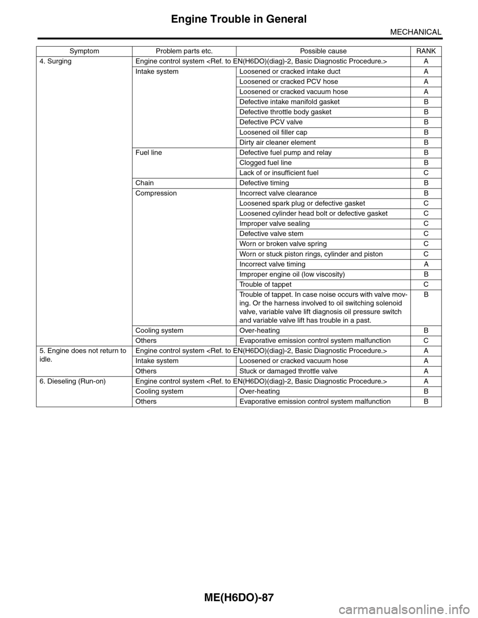
4. Surging Engine control system
Intake system Loosened or cracked intake duct A
Loosened or cracked PCV hose A
Loosened or cracked vacuum hose A
Defective intake manifold gasket B
Defective throttle body gasket B
Defective PCV valve B
Loosened oil filler cap B
Dirty air cleaner element B
Fuel line Defective fuel pump and relay B
Clogged fuel line B
Lack of or insufficient fuel C
Chain Defective timing B
Compression Incorrect valve clearance B
Loosened spark plug or defective gasket C
Loosened cylinder head bolt or defective gasket C
Improper valve sealing C
Defective valve stem C
Wor n or broken valve spr ing C
Wor n or stuck piston r ings, cylinder and piston C
Incorrect valve timing A
Improper engine oil (low viscosity) B
Tr o u b l e o f t a p p e t C
Tr o u b l e o f t a p p e t . I n c a s e n o i s e o c c u r s w i t h v a l v e m o v -
ing. Or the harness involved to oil switching solenoid
valve, variable valve lift diagnosis oil pressure switch
and variable valve lift has trouble in a past.
B
Cooling system Over-heating B
Others Evaporative emission control system malfunction C
5. Engine does not return to
idle.
Engine control system
Intake system Loosened or cracked vacuum hose A
Others Stuck or damaged throttle valve A
6. Dieseling (Run-on) Engine control system
Cooling system Over-heating B
Others Evaporative emission control system malfunction B
Symptom Problem parts etc. Possible cause RANK
Page 2029 of 2453
5AT-13
General Description
AUTOMATIC TRANSMISSION
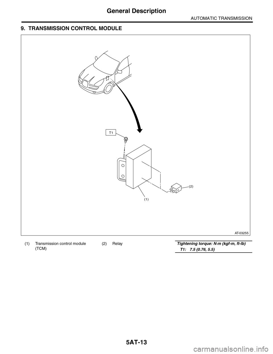
9. TRANSMISSION CONTROL MODULE
(1) Transmission control module
(TCM)
(2) RelayTightening torque: N·m (kgf-m, ft-lb)
T1: 7.5 (0.76, 5.5)
(2)
(1)
T1
AT-03255
Page 2072 of 2453
5AT-56
Transmission Control Module (TCM)
AUTOMATIC TRANSMISSION
19.Transmission Control Mod-
ule (TCM)
A: REMOVAL
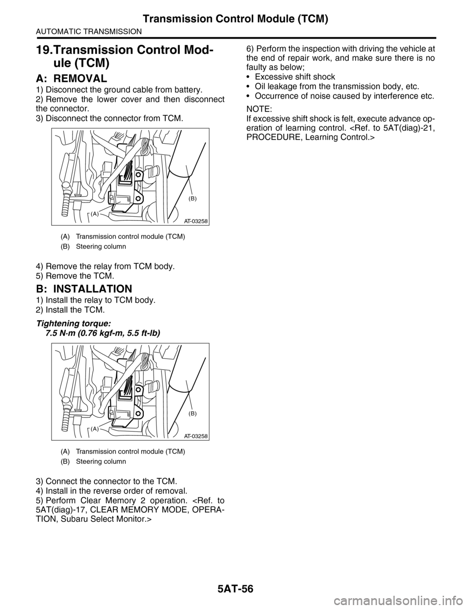
1) Disconnect the ground cable from battery.
2) Remove the lower cover and then disconnect
the connector.
3) Disconnect the connector from TCM.
4) Remove the relay from TCM body.
5) Remove the TCM.
B: INSTALLATION
1) Install the relay to TCM body.
2) Install the TCM.
Tightening torque:
7.5 N·m (0.76 kgf-m, 5.5 ft-lb)
3) Connect the connector to the TCM.
4) Install in the reverse order of removal.
5) Perform Clear Memory 2 operation.
TION, Subaru Select Monitor.>
6) Perform the inspection with driving the vehicle at
the end of repair work, and make sure there is no
faulty as below;
•Excessive shift shock
•Oil leakage from the transmission body, etc.
•Occurrence of noise caused by interference etc.
NOTE:
If excessive shift shock is felt, execute advance op-
eration of learning control.
(A) Transmission control module (TCM)
(B) Steering column
(A) Transmission control module (TCM)
(B) Steering column
AT-03258(A)
(B)
AT-03258(A)
(B)
Page 2129 of 2453
5AT(diag)-12
Transmission Control Module (TCM) I/O Signal
AUTOMATIC TRANSMISSION (DIAGNOSTICS)
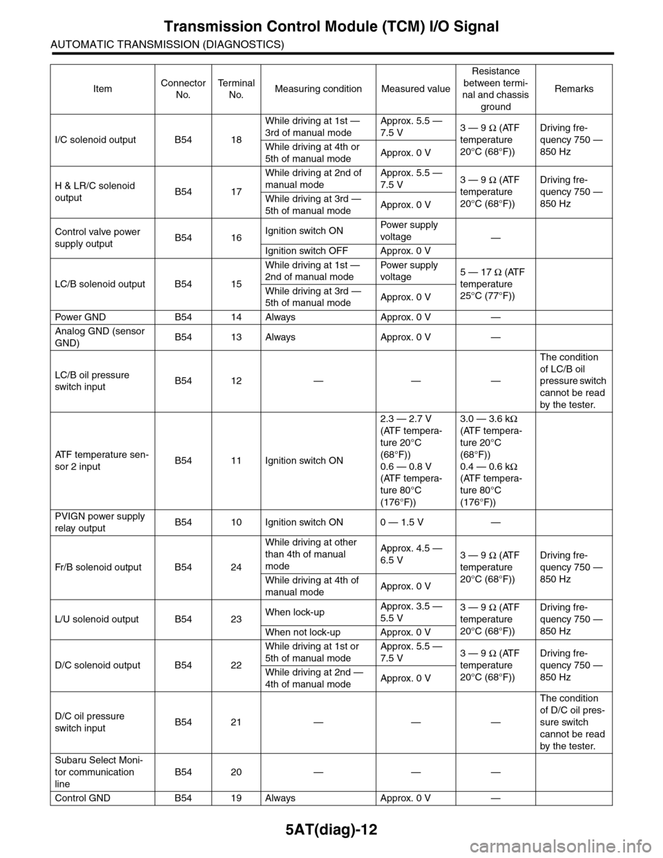
I/C solenoid output B54 18
While driving at 1st —
3rd of manual mode
Approx. 5.5 —
7.5 V3 — 9 Ω (ATF
temperature
20°C (68°F))
Driving fre-
quency 750 —
850 HzWhile driving at 4th or
5th of manual modeApprox. 0 V
H & LR/C solenoid
outputB54 17
While driving at 2nd of
manual mode
Approx. 5.5 —
7.5 V3 — 9 Ω (ATF
temperature
20°C (68°F))
Driving fre-
quency 750 —
850 HzWhile driving at 3rd —
5th of manual modeApprox. 0 V
Control valve power
supply outputB54 16Ignition switch ONPow er s up p ly
voltage—
Ignition switch OFF Approx. 0 V
LC/B solenoid output B54 15
While driving at 1st —
2nd of manual mode
Pow er s up p ly
voltage5 — 17 Ω (ATF
temperature
25°C (77°F))
While driving at 3rd —
5th of manual modeApprox. 0 V
Pow er GN D B 5 4 1 4 A lways A pp r ox . 0 V —
Analog GND (sensor
GND)B54 13 Always Approx. 0 V —
LC/B oil pressure
switch inputB54 12 — — —
The condition
of LC/B oil
pressure switch
cannot be read
by the tester.
AT F t e m p e r a t u r e s e n -
sor 2 inputB54 11 Ignition switch ON
2.3 — 2.7 V
(ATF tempera-
ture 20°C
(68°F))
0.6 — 0.8 V
(ATF tempera-
ture 80°C
(176°F))
3.0 — 3.6 kΩ
(ATF tempera-
ture 20°C
(68°F))
0.4 — 0.6 kΩ
(ATF tempera-
ture 80°C
(176°F))
PVIGN power supply
relay outputB54 10 Ignition switch ON 0 — 1.5 V —
Fr / B so le n oi d o u tp u t B 5 4 2 4
While driving at other
than 4th of manual
mode
Approx. 4.5 —
6.5 V3 — 9 Ω (ATF
temperature
20°C (68°F))
Driving fre-
quency 750 —
850 HzWhile driving at 4th of
manual modeApprox. 0 V
L/U solenoid output B54 23When lock-upApprox. 3.5 —
5.5 V3 — 9 Ω (ATF
temperature
20°C (68°F))
Driving fre-
quency 750 —
850 HzWhen not lock-up Approx. 0 V
D/C solenoid output B54 22
While driving at 1st or
5th of manual mode
Approx. 5.5 —
7.5 V3 — 9 Ω (ATF
temperature
20°C (68°F))
Driving fre-
quency 750 —
850 HzWhile driving at 2nd —
4th of manual modeApprox. 0 V
D/C oil pressure
switch inputB54 21 — — —
The condition
of D/C oil pres-
sure switch
cannot be read
by the tester.
Subaru Select Moni-
tor communication
line
B54 20 — — —
Control GND B54 19 Always Approx. 0 V —
ItemConnector
No.
Te r m i n a l
No.Measuring condition Measured value
Resistance
between termi-
nal and chassis
ground
Remarks
Page 2131 of 2453
5AT(diag)-14
Transmission Control Module (TCM) I/O Signal
AUTOMATIC TRANSMISSION (DIAGNOSTICS)
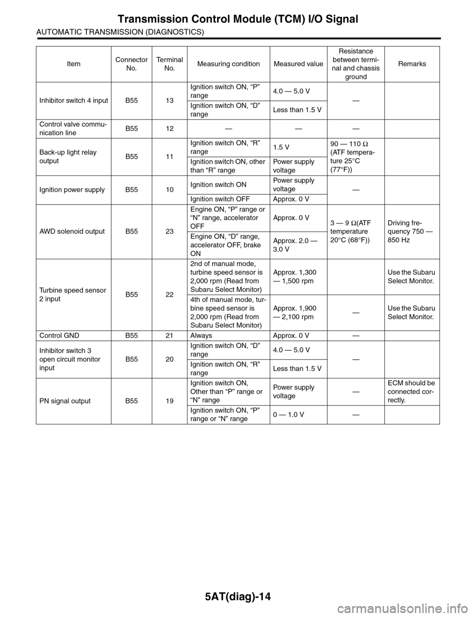
Inhibitor switch 4 input B55 13
Ignition switch ON, “P”
range4.0 — 5.0 V
—
Ignition switch ON, “D”
rangeLess than 1.5 V
Control valve commu-
nication lineB55 12 — — —
Back-up light relay
outputB55 11
Ignition switch ON, “R”
range1.5 V90 — 110 Ω
(ATF tempera-
ture 25°C
(77°F))
Ignition switch ON, other
than “R” range
Pow er s up p ly
voltage
Ignition power supply B55 10Ignition switch ONPow er s up p ly
voltage—
Ignition switch OFF Approx. 0 V
AW D s o le n oi d o u tp u t B 5 5 2 3
Engine ON, “P” range or
“N” range, accelerator
OFF
Approx. 0 V3 — 9 Ω(ATF
temperature
20°C (68°F))
Driving fre-
quency 750 —
850 HzEngine ON, “D” range,
accelerator OFF, brake
ON
Approx. 2.0 —
3.0 V
Tu r b i n e s p e e d s e n s o r
2 inputB55 22
2nd of manual mode,
turbine speed sensor is
2,000 rpm (Read from
Subaru Select Monitor)
Approx. 1,300
— 1,500 rpm
Use the Subaru
Select Monitor.
4th of manual mode, tur-
bine speed sensor is
2,000 rpm (Read from
Subaru Select Monitor)
Approx. 1,900
— 2,100 rpm—Use the Subaru
Select Monitor.
Control GND B55 21 Always Approx. 0 V —
Inhibitor switch 3
open circuit monitor
input
B55 20
Ignition switch ON, “D”
range4.0 — 5.0 V
—
Ignition switch ON, “R”
rangeLess than 1.5 V
PN signal output B55 19
Ignition switch ON,
Other than “P” range or
“N” range
Pow er s up p ly
voltage—
ECM should be
connected cor-
rectly.
Ignition switch ON, “P”
range or “N” range0 — 1.0 V —
ItemConnector
No.
Te r m i n a l
No.Measuring condition Measured value
Resistance
between termi-
nal and chassis
ground
Remarks