Page 1554 of 2453

EN(H6DO)(diag)-393
General Diagnostic Table
ENGINE (DIAGNOSTICS)
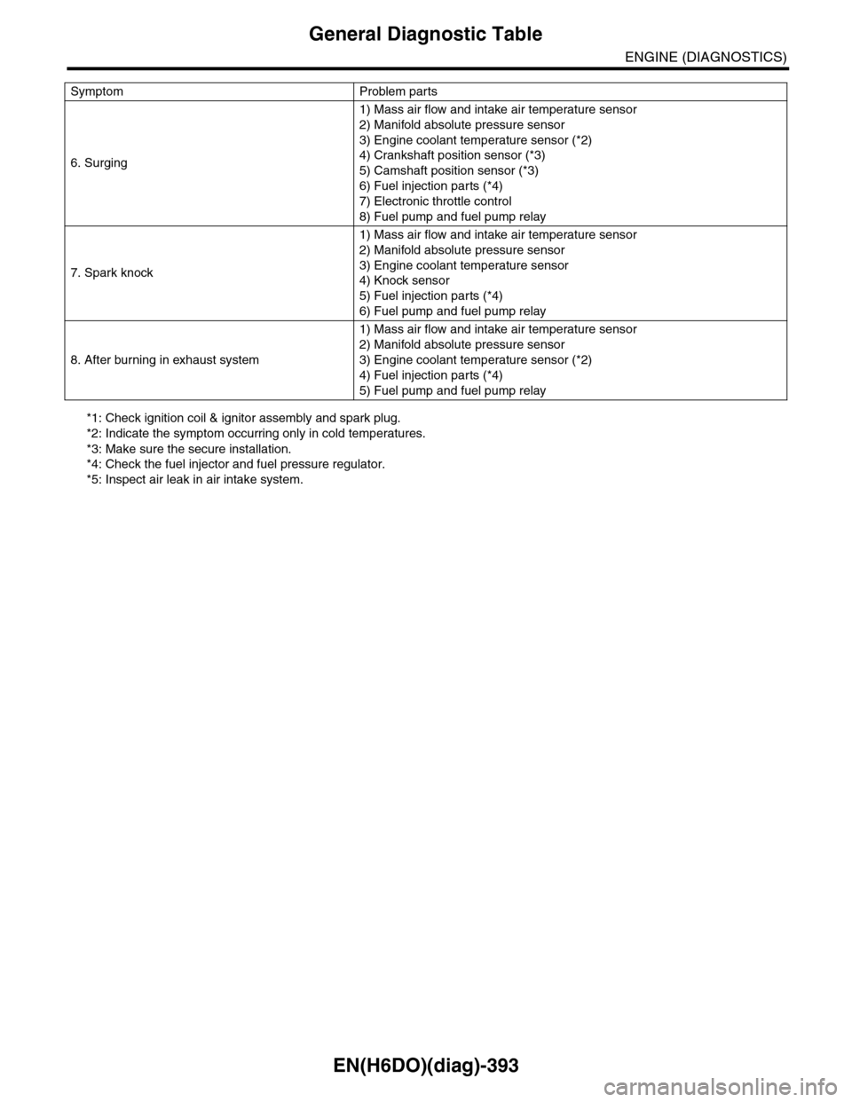
*1: Check ignition coil & ignitor assembly and spark plug.
*2: Indicate the symptom occurring only in cold temperatures.
*3: Make sure the secure installation.
*4: Check the fuel injector and fuel pressure regulator.
*5: Inspect air leak in air intake system.
6. Surging
1) Mass air flow and intake air temperature sensor
2) Manifold absolute pressure sensor
3) Engine coolant temperature sensor (*2)
4) Crankshaft position sensor (*3)
5) Camshaft position sensor (*3)
6) Fuel injection parts (*4)
7) Electronic throttle control
8) Fuel pump and fuel pump relay
7. Spark knock
1) Mass air flow and intake air temperature sensor
2) Manifold absolute pressure sensor
3) Engine coolant temperature sensor
4) Knock sensor
5) Fuel injection parts (*4)
6) Fuel pump and fuel pump relay
8. After burning in exhaust system
1) Mass air flow and intake air temperature sensor
2) Manifold absolute pressure sensor
3) Engine coolant temperature sensor (*2)
4) Fuel injection parts (*4)
5) Fuel pump and fuel pump relay
Symptom Problem parts
Page 1594 of 2453
FU(H6DO)-33
Main Relay
FUEL INJECTION (FUEL SYSTEMS)
17.Main Relay
A: REMOVAL
1) Disconnect the ground cable from battery.
2) Remove the glove box.
AL, Glove Box.>
3) Remove the harness cover (A).
4) Disconnect the connectors from main relay.
B: INSTALLATION
Install in the reverse order of removal.
FU-02092
(A)
FU-02406
Page 1595 of 2453
FU(H6DO)-34
Fuel Pump Relay
FUEL INJECTION (FUEL SYSTEMS)
18.Fuel Pump Relay
A: REMOVAL
1) Disconnect the ground cable from battery.
2) Remove the glove box.
AL, Glove Box.>
3) Remove the harness cover (A).
4) Disconnect the connector from fuel pump relay.
B: INSTALLATION
Install in the reverse order of removal.
FU-02092
(A)
FU-02407
Page 1596 of 2453
FU(H6DO)-35
Electronic Throttle Control Relay
FUEL INJECTION (FUEL SYSTEMS)
19.Electronic Throttle Control
Relay
A: REMOVAL
1) Disconnect the ground cable from battery.
2) Remove the glove box.
AL, Glove Box.>
3) Remove the harness cover (A).
4) Disconnect the connector from electric throttle
control relay.
B: INSTALLATION
Install in the reverse order of removal.
FU-02092
(A)
FU-02408
Page 1813 of 2453
GD(H6DO)-201
Diagnostic Trouble Code (DTC) Detecting Criteria
GENERAL DESCRIPTION
EC:DTC P2101 THROTTLE ACTUATOR CONTROL MOTOR CIRCUIT RANGE/
PERFORMANCE
1. OUTLINE OF DIAGNOSIS
Judge as NG when the motor current becomes large or drive circuit is heated.
2. COMPONENT DESCRIPTION
3. ENABLE CONDITIONS
4. GENERAL DRIVING CYCLE
Always perform the diagnosis continuously.
5. DIAGNOSTIC METHOD
Judge as OK and clear the NG when the malfunction criteria below are met.
(1) Engine control module (ECM) (4) Drive circuit (6) Electronic throttle control relay
(2) Detecting circuit (5) Temperature detection circuit (7) Motor
(3) Overcurrent detection circuit
Secondary Parameters Enable Conditions
Under control of electronic throttle con-
trol
ON
Judgment Value
Malfunction Criteria Threshold Value
Motor current≤ 8 A
Drive circuit inner temperature≤ 175°C (347°F)
EN-01867
(3)(2)
(5)(2)
(4)
(1)
(6)
(7)
12V 12V
Page 1815 of 2453

GD(H6DO)-203
Diagnostic Trouble Code (DTC) Detecting Criteria
GENERAL DESCRIPTION
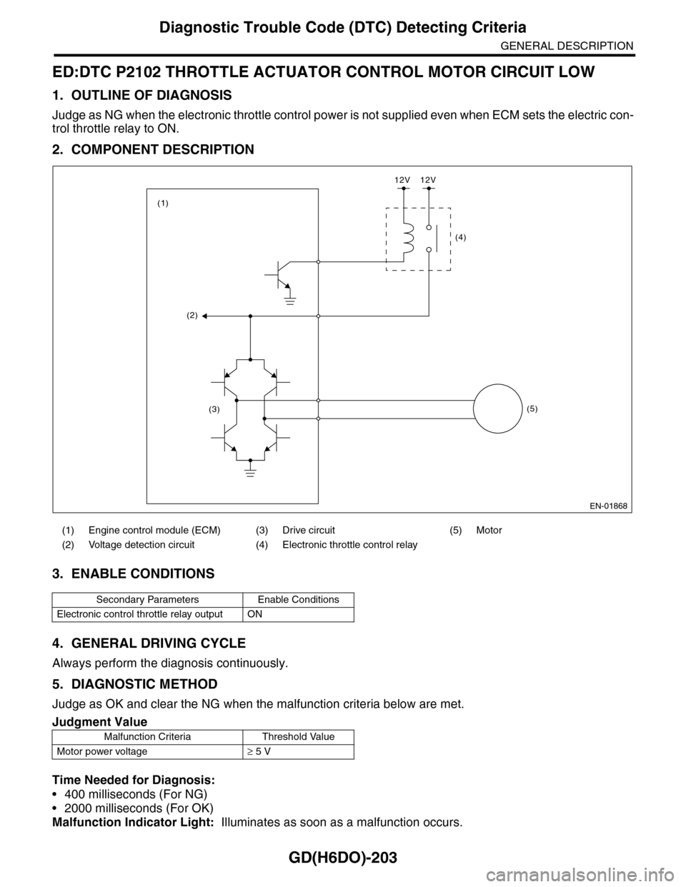
ED:DTC P2102 THROTTLE ACTUATOR CONTROL MOTOR CIRCUIT LOW
1. OUTLINE OF DIAGNOSIS
Judge as NG when the electronic throttle control power is not supplied even when ECM sets the electric con-
trol throttle relay to ON.
2. COMPONENT DESCRIPTION
3. ENABLE CONDITIONS
4. GENERAL DRIVING CYCLE
Always perform the diagnosis continuously.
5. DIAGNOSTIC METHOD
Judge as OK and clear the NG when the malfunction criteria below are met.
Time Needed for Diagnosis:
•400 milliseconds (For NG)
•2000 milliseconds (For OK)
Malfunction Indicator Light: Illuminates as soon as a malfunction occurs.
(1) Engine control module (ECM) (3) Drive circuit (5) Motor
(2) Voltage detection circuit (4) Electronic throttle control relay
Secondary Parameters Enable Conditions
Electronic control throttle relay output ON
Judgment Value
Malfunction Criteria Threshold Value
Motor power voltage≥ 5 V
EN-01868
(2)
(3)
(1)
(4)
(5)
12V 12V
Page 1817 of 2453
GD(H6DO)-205
Diagnostic Trouble Code (DTC) Detecting Criteria
GENERAL DESCRIPTION
EE:DTC P2103 THROTTLE ACTUATOR CONTROL MOTOR CIRCUIT HIGH
1. OUTLINE OF DIAGNOSIS
Judge as NG when the electronic throttle control power is not supplied even when ECM sets the electric throt-
tle control relay to OFF.
2. COMPONENT DESCRIPTION
3. ENABLE CONDITIONS
4. GENERAL DRIVING CYCLE
•When ignition switch ON → OFF
•Ignition switch OFF → ON (Only after clearing memory)
5. DIAGNOSTIC METHOD
Judge as OK and clear the NG when the malfunction criteria below are met.
(1) Engine control module (ECM) (3) Drive circuit (5) Motor
(2) Voltage detection circuit (4) Electronic throttle control relay
Secondary Parameters Enable Conditions
Electronic control throttle relay output OFF
Judgment Value
Malfunction Criteria Threshold Value
Motor power voltage≤ 5 V
EN-01868
(2)
(3)
(1)
(4)
(5)
12V 12V
Page 1949 of 2453

ME(H6DO)-83
Engine Trouble in General
MECHANICAL
28.Engine Trouble in General
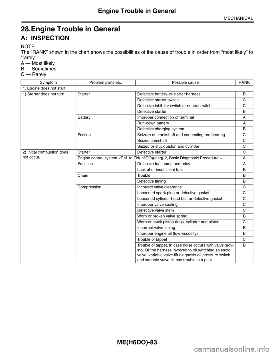
A: INSPECTION
NOTE:
The “RANK” shown in the chart shows the possibilities of the cause of trouble in order from “most likely” to
“rarely”.
A — Most likely
B — Sometimes
C — Rarely
Symptom Problem parts etc. Possible cause RANK
1. Engine does not start.
1) Starter does not turn. Starter Defective battery-to-starter harness B
Defective starter switch C
Defective inhibitor switch or neutral switch C
Defective starter B
Battery Improper connection of terminal A
Run-down battery A
Defective charging system B
Fr iction Seizure of crankshaft and connecting rod bear ing C
Seized camshaft C
Seized or stuck piston and cylinder C
2) Initial combustion does
not occur.
Starter Defective starter C
Engine control system A
Fuel line Defective fuel pump and relay A
Lack of or insufficient fuel B
Chain Trouble B
Defective timing B
Compression Incorrect valve clearance C
Loosened spark plug or defective gasket C
Loosened cylinder head bolt or defective gasket C
Improper valve sealing C
Defective valve stem C
Wor n or broken valve spr ing B
Wor n or stuck piston r ings, cylinder and piston C
Incorrect valve timing B
Improper engine oil (low viscosity) B
Tr o u b l e o f t a p p e t C
Tr o u b l e o f t a p p e t . I n c a s e n o i s e o c c u r s w i t h v a l v e m o v -
ing. Or the harness involved to oil switching solenoid
valve, variable valve lift diagnosis oil pressure switch
and variable valve lift has trouble in a past.
B