2009 SUBARU TRIBECA ECU
[x] Cancel search: ECUPage 1167 of 2453
EN(H6DO)(diag)-6
General Description
ENGINE (DIAGNOSTICS)
C: NOTE
1. GENERAL DESCRIPTION
•The on-board diagnostics (OBD) system detects
and indicates a fault in various inputs and outputs
of the complex electronic control. Malfunction indi-
cator light in the combination meter indicates oc-
currence of a fault or trouble.
•Further, against such a failure or sensors as may
disable the drive, the fail-safe function is provided
to ensure the minimal drivability.
•The OBD system incorporated with the vehicles
within this engine family complies with OBD-II Reg-
ulations. The OBD system monitors the compo-
nents and the system malfunction listed in Engine
Section which affects on emissions.
•When the system decides that a malfunction oc-
curs, malfunction indicator light illuminates. At the
same time of the malfunction indicator light illumi-
nation or blinking, a DTC and a freeze frame en-
gine conditions are stored into on-board computer.
•The OBD system stores freeze frame engine
condition data (engine load, engine coolant tem-
perature, fuel trim, engine speed and vehicle
speed, etc.) into on-board computer when it detects
a malfunction first.
•If the OBD system detects the various malfunc-
tions including the fault of fuel trim or misfire, the
OBD system first stores freeze frame engine condi-
tions about fuel trim or misfire.
•When the malfunction does not occur again for
three consecutive driving cycles, malfunction indi-
cator light is turned off, but DTC remains at on-
board computer.
•When troubleshooting the vehicle which com-
plies with OBD-II Regulations, connect the Subaru
Select Monitor or general scan tool to the vehicle.
2. ENGINE AND EMISSION CONTROL SYS-
TEM
•The Multipoint Fuel Injection (MFI) system is a
system that supplies the optimum air-fuel mixture
to the engine for all the various operating condi-
tions through the use of the latest electronic tech-
nology.
With this system fuel, which is pressurized at a con-
stant pressure, is injected into the intake air pas-
sage of the cylinder head. The injection quantity of
fuel is controlled by an intermittent injection system
where the electro-magnetic injection valve (fuel in-
jector) opens only for a short period of time, de-
pending on the quantity of air required for one cycle
of operation. In actual operation, the injection quan-
tity is determined by the duration of an electric
pulse applied to the fuel injector and this permits
simple, yet highly precise metering of the fuel.
•Further, all the operating conditions of the engine
are converted into electric signals, and this results
in additional features of the system, such as large
improved adaptability, easier addition of compen-
sating element etc.
The MFI system also has the following features:
•Reduced emission of harmful exhaust gases.
•Reduced in fuel consumption.
•Increased engine output.
•Superior acceleration and deceleration.
•Superior startability and warm-up perfor-
mance in cold weather since compensation is
made for coolant and intake air temperature.
Page 1198 of 2453
EN(H6DO)(diag)-37
Inspection Mode
ENGINE (DIAGNOSTICS)
1. PREPARATION FOR THE INSPECTION
MODE
1) Check battery voltage is more than 12 V and fuel
remains half [20 to 40 2 (5.3 to 10.6 US gal, 4.4 to
8.8 Imp gal)].
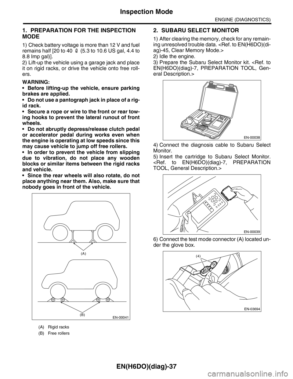
2) Lift-up the vehicle using a garage jack and place
it on rigid racks, or drive the vehicle onto free roll-
ers.
WARNING:
•Before lifting-up the vehicle, ensure parking
brakes are applied.
•Do not use a pantograph jack in place of a rig-
id rack.
•Secure a rope or wire to the front or rear tow-
ing hooks to prevent the lateral runout of front
wheels.
•Do not abruptly depress/release clutch pedal
or accelerator pedal during works even when
the engine is operating at low speeds since this
may cause vehicle to jump off free rollers.
•In order to prevent the vehicle from slipping
due to vibration, do not place any wooden
blocks or similar items between the rigid racks
and vehicle.
•Since the rear wheels will also rotate, do not
place anything near them. Also, make sure that
nobody goes in front of the vehicle.
2. SUBARU SELECT MONITOR
1) After clearing the memory, check for any remain-
ing unresolved trouble data.
2) Idle the engine.
3) Prepare the Subaru Select Monitor kit.
eral Description.>
4) Connect the diagnosis cable to Subaru Select
Monitor.
5) Insert the cartridge to Subaru Select Monitor.
6) Connect the test mode connector (A) located un-
der the glove box.
(A) Rigid racks
(B) Free rollers
EN-00041
(A)
(B)
EN-00038
EN-00039
EN-03694
(4)
Page 1227 of 2453
EN(H6DO)(diag)-66
Diagnostics for Engine Starting Failure
ENGINE (DIAGNOSTICS)
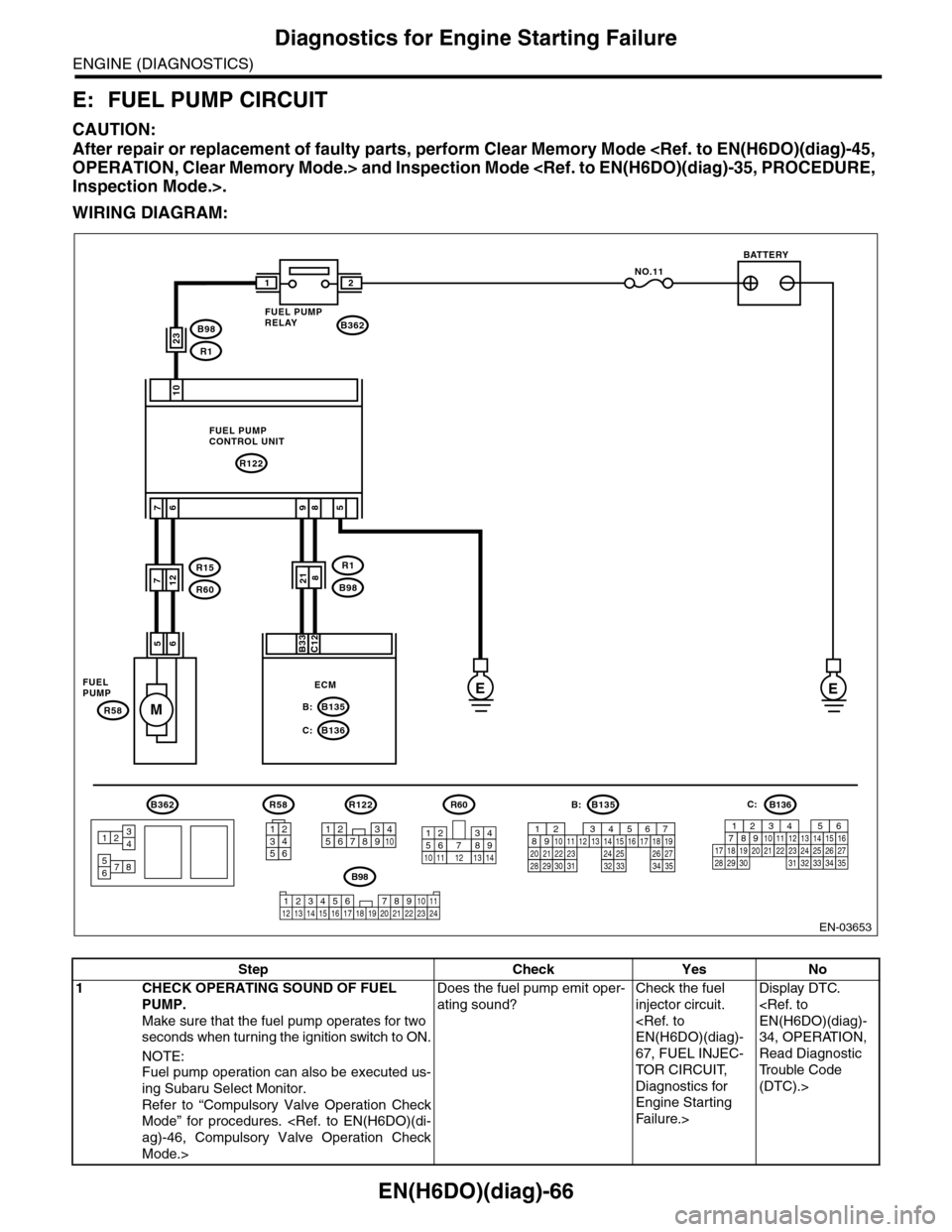
E: FUEL PUMP CIRCUIT
CAUTION:
After repair or replacement of faulty parts, perform Clear Memory Mode
WIRING DIAGRAM:
EN-03653
EE
M
10
76
56
NO.11
B362
R122
B135B:
B136C:
R58
7
B33C12
21
985
FUEL PUMPCONTROL UNIT
FUELPUMPECM
BATTERY
FUEL PUMPRELAY
B362
5678
3412
R1
B98218
23B98
R1
R15
R60712
R58
2
546
13
B135B:
567821943102422 23 2511 12 13 14 1526 2728
16 17 18 1920 2129 30 31 32 33 34 35
R122
34125891067
B98
123456 78910 1112 13 16 1714 15 18 19 2021222324
R60
12
10115634897131412
B136
16101112131415252430
9871718192028212223293231
123456
2726333435
C:
Step Check Yes No
1CHECK OPERATING SOUND OF FUEL
PUMP.
Make sure that the fuel pump operates for two
seconds when turning the ignition switch to ON.
NOTE:
Fuel pump operation can also be executed us-
ing Subaru Select Monitor.
Refer to “Compulsory Valve Operation Check
Mode” for procedures.
Mode.>
Does the fuel pump emit oper-
ating sound?
Check the fuel
injector circuit.
67, FUEL INJEC-
TOR CIRCUIT,
Diagnostics for
Engine Starting
Fa il u r e. >
Display DTC.
34, OPERATION,
Read Diagnostic
Tr o u b l e C o d e
(DTC).>
Page 1238 of 2453
EN(H6DO)(diag)-77
Diagnostic Procedure with Diagnostic Trouble Code (DTC)
ENGINE (DIAGNOSTICS)
18.Diagnostic Procedure with Diagnostic Trouble Code (DTC)
A: DTC P0011 INTAKE CAMSHAFT POSITION TIMING - OVER-ADVANCED
(BANK 1)
DTC DETECTING CONDITION:
•Detected when two consecutive driving cycles with fault occur.
•GENERAL DESCRIPTION
TROUBLE SYMPTOM:
•Engine stalls.
•Erroneous idling
CAUTION:
After repair or replacement of faulty parts, perform Clear Memory Mode
Step Check Yes No
1CHECK ANY OTHER DTC ON DISPLAY.Is any other DTC displayed? Inspect the rele-
vant DTC using
“List of Diagnostic
Tr o u b l e C o d e
(DTC).”
69, List of Diag-
nostic Trouble
Code (DTC).>
Go to step 2.
2CHECK CURRENT DATA.
1) Start the engine and let it idle.
2) Measure the AVCS system operating angle
and oil flow control solenoid valve duty output
using Subaru Select Monitor or general scan
tool.
NOTE:•Subaru Select Monitor
For detailed operation procedures, refer to
“READ CURRENT DATA FOR ENGINE”.
tor.>
•General scan tool
For detailed operation procedure, refer to the
general scan tool operation manual.
Is the AVCS system operating
angle approx. 0 deg., and oil
flow control solenoid valve duty
output approx. 10%?
Check the follow-
ing item and repair
or replace if nec-
essary.
•Oil pipe (clog)
•Oil flow con-
trol solenoid
valve (clog or
dirt of oil rout-
ing, setting of
spring, clog of
valve)
•Intake cam-
shaft (dirt, dam-
age of
camshaft)
•Timing chain
(matching of
timing mark)
A temporary mal-
function. Perform
the following, and
clean the oil rout-
ing.
Replace the
engine oil and idle
the engine for 5
minutes, and then
replace the oil filter
and engine oil.
Page 1239 of 2453
EN(H6DO)(diag)-78
Diagnostic Procedure with Diagnostic Trouble Code (DTC)
ENGINE (DIAGNOSTICS)
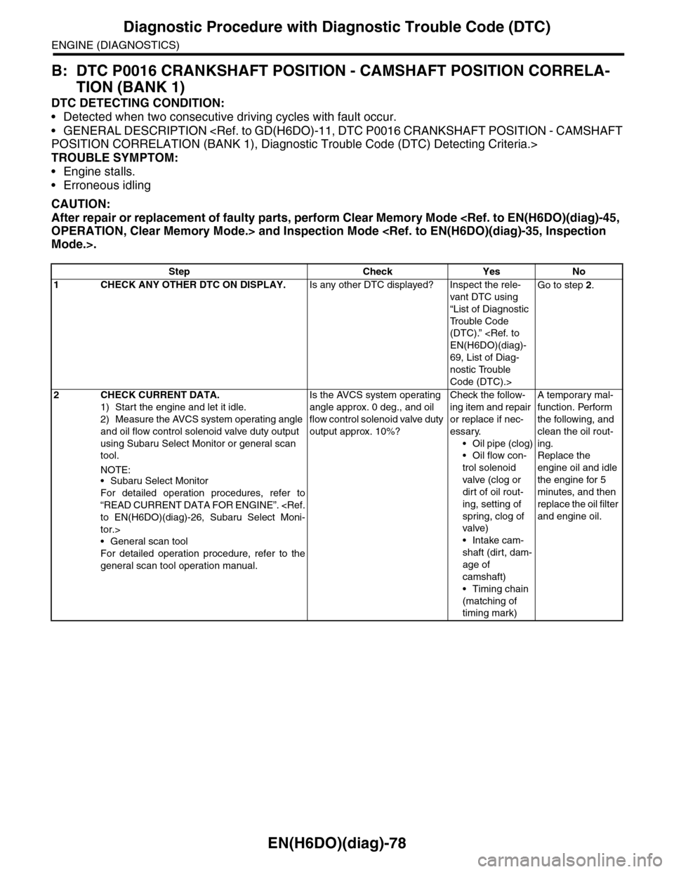
B: DTC P0016 CRANKSHAFT POSITION - CAMSHAFT POSITION CORRELA-
TION (BANK 1)
DTC DETECTING CONDITION:
•Detected when two consecutive driving cycles with fault occur.
•GENERAL DESCRIPTION
TROUBLE SYMPTOM:
•Engine stalls.
•Erroneous idling
CAUTION:
After repair or replacement of faulty parts, perform Clear Memory Mode
Step Check Yes No
1CHECK ANY OTHER DTC ON DISPLAY.Is any other DTC displayed? Inspect the rele-
vant DTC using
“List of Diagnostic
Tr o u b l e C o d e
(DTC).”
69, List of Diag-
nostic Trouble
Code (DTC).>
Go to step 2.
2CHECK CURRENT DATA.
1) Start the engine and let it idle.
2) Measure the AVCS system operating angle
and oil flow control solenoid valve duty output
using Subaru Select Monitor or general scan
tool.
NOTE:•Subaru Select Monitor
For detailed operation procedures, refer to
“READ CURRENT DATA FOR ENGINE”.
tor.>
•General scan tool
For detailed operation procedure, refer to the
general scan tool operation manual.
Is the AVCS system operating
angle approx. 0 deg., and oil
flow control solenoid valve duty
output approx. 10%?
Check the follow-
ing item and repair
or replace if nec-
essary.
•Oil pipe (clog)
•Oil flow con-
trol solenoid
valve (clog or
dirt of oil rout-
ing, setting of
spring, clog of
valve)
•Intake cam-
shaft (dirt, dam-
age of
camshaft)
•Timing chain
(matching of
timing mark)
A temporary mal-
function. Perform
the following, and
clean the oil rout-
ing.
Replace the
engine oil and idle
the engine for 5
minutes, and then
replace the oil filter
and engine oil.
Page 1240 of 2453
EN(H6DO)(diag)-79
Diagnostic Procedure with Diagnostic Trouble Code (DTC)
ENGINE (DIAGNOSTICS)
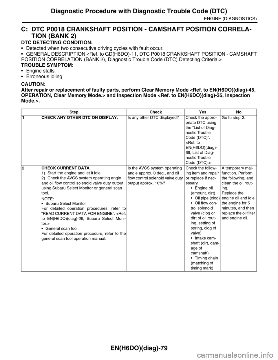
C: DTC P0018 CRANKSHAFT POSITION - CAMSHAFT POSITION CORRELA-
TION (BANK 2)
DTC DETECTING CONDITION:
•Detected when two consecutive driving cycles with fault occur.
•GENERAL DESCRIPTION
TROUBLE SYMPTOM:
•Engine stalls.
•Erroneous idling
CAUTION:
After repair or replacement of faulty parts, perform Clear Memory Mode
Step Check Yes No
1CHECK ANY OTHER DTC ON DISPLAY.Is any other DTC displayed? Check the appro-
priate DTC using
the “List of Diag-
nostic Trouble
Code (DTC)”.
69, List of Diag-
nostic Trouble
Code (DTC).>
Go to step 2.
2CHECK CURRENT DATA.
1) Start the engine and let it idle.
2) Check the AVCS system operating angle
and oil flow control solenoid valve duty output
using Subaru Select Monitor or general scan
tool.
NOTE:
•Subaru Select Monitor
For detailed operation procedures, refer to
“READ CURRENT DATA FOR ENGINE”.
tor.>
•General scan tool
For detailed operation procedure, refer to the
general scan tool operation manual.
Is the AVCS system operating
angle approx. 0 deg., and oil
flow control solenoid valve duty
output approx. 10%?
Check the follow-
ing item and repair
or replace if nec-
essary.
•Engine oil
(amount, dirt)
•Oil pipe (clog)
•Oil flow con-
trol solenoid
valve (clog or
dirt of oil rout-
ing, setting of
spring, clog of
valve)
•Intake cam-
shaft (dirt, dam-
age of
camshaft)
•Timing chain
(matching of
timing mark)
A temporary mal-
function. Perform
the following, and
clean the oil rout-
ing.
Replace the
engine oil and idle
the engine for 5
minutes, and then
replace the oil filter
and engine oil.
Page 1241 of 2453
EN(H6DO)(diag)-80
Diagnostic Procedure with Diagnostic Trouble Code (DTC)
ENGINE (DIAGNOSTICS)
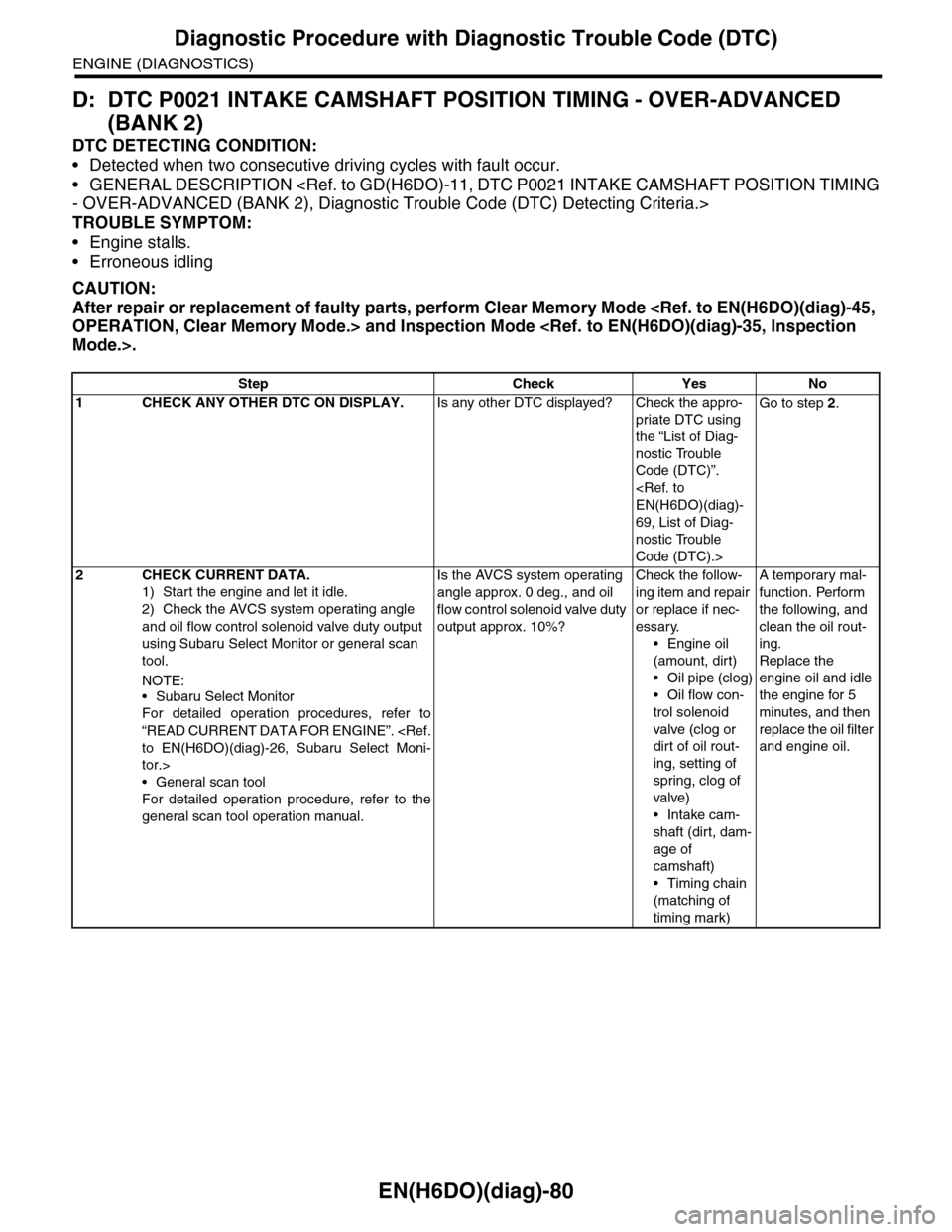
D: DTC P0021 INTAKE CAMSHAFT POSITION TIMING - OVER-ADVANCED
(BANK 2)
DTC DETECTING CONDITION:
•Detected when two consecutive driving cycles with fault occur.
•GENERAL DESCRIPTION
TROUBLE SYMPTOM:
•Engine stalls.
•Erroneous idling
CAUTION:
After repair or replacement of faulty parts, perform Clear Memory Mode
Step Check Yes No
1CHECK ANY OTHER DTC ON DISPLAY.Is any other DTC displayed? Check the appro-
priate DTC using
the “List of Diag-
nostic Trouble
Code (DTC)”.
69, List of Diag-
nostic Trouble
Code (DTC).>
Go to step 2.
2CHECK CURRENT DATA.
1) Start the engine and let it idle.
2) Check the AVCS system operating angle
and oil flow control solenoid valve duty output
using Subaru Select Monitor or general scan
tool.
NOTE:
•Subaru Select Monitor
For detailed operation procedures, refer to
“READ CURRENT DATA FOR ENGINE”.
tor.>
•General scan tool
For detailed operation procedure, refer to the
general scan tool operation manual.
Is the AVCS system operating
angle approx. 0 deg., and oil
flow control solenoid valve duty
output approx. 10%?
Check the follow-
ing item and repair
or replace if nec-
essary.
•Engine oil
(amount, dirt)
•Oil pipe (clog)
•Oil flow con-
trol solenoid
valve (clog or
dirt of oil rout-
ing, setting of
spring, clog of
valve)
•Intake cam-
shaft (dirt, dam-
age of
camshaft)
•Timing chain
(matching of
timing mark)
A temporary mal-
function. Perform
the following, and
clean the oil rout-
ing.
Replace the
engine oil and idle
the engine for 5
minutes, and then
replace the oil filter
and engine oil.
Page 1246 of 2453
EN(H6DO)(diag)-85
Diagnostic Procedure with Diagnostic Trouble Code (DTC)
ENGINE (DIAGNOSTICS)
G: DTC P0030 HO2S HEATER CONTROL CIRCUIT (BANK 1 SENSOR 1)
DTC DETECTING CONDITION:
•Detected when two consecutive driving cycles with fault occur.
•GENERAL DESCRIPTION
CAUTION:
After repair or replacement of faulty parts, perform Clear Memory Mode