2009 SUBARU TRIBECA ECU
[x] Cancel search: ECUPage 902 of 2453
PS-22
Steering Gearbox
POWER ASSISTED SYSTEM (POWER STEERING)
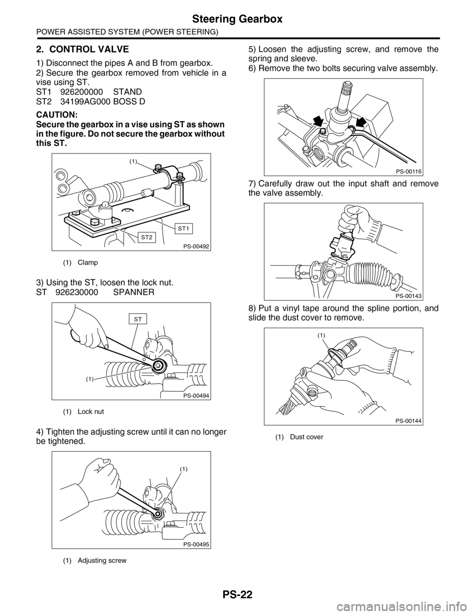
2. CONTROL VALVE
1) Disconnect the pipes A and B from gearbox.
2) Secure the gearbox removed from vehicle in a
vise using ST.
ST1 926200000 STAND
ST2 34199AG000 BOSS D
CAUTION:
Secure the gearbox in a vise using ST as shown
in the figure. Do not secure the gearbox without
this ST.
3) Using the ST, loosen the lock nut.
ST 926230000 SPANNER
4) Tighten the adjusting screw until it can no longer
be tightened.
5) Loosen the adjusting screw, and remove the
spring and sleeve.
6) Remove the two bolts securing valve assembly.
7) Carefully draw out the input shaft and remove
the valve assembly.
8) Put a vinyl tape around the spline portion, and
slide the dust cover to remove.
(1) Clamp
(1) Lock nut
(1) Adjusting screw
PS-00492
(1)
ST1
ST2
PS-00494
ST
(1)
PS-00495
(1)
(1) Dust cover
PS-00116
PS-00143
PS-00144
(1)
Page 905 of 2453
PS-25
Steering Gearbox
POWER ASSISTED SYSTEM (POWER STEERING)
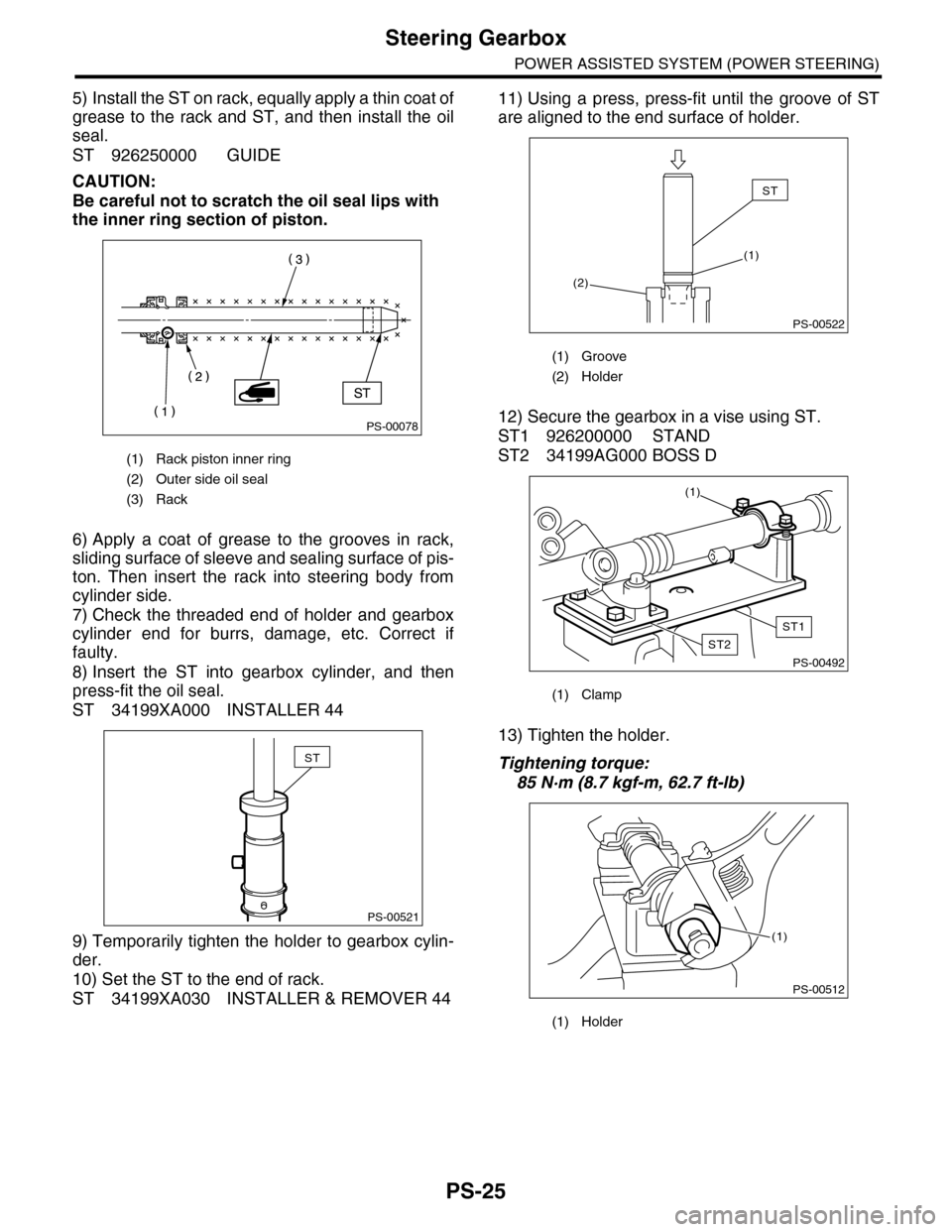
5) Install the ST on rack, equally apply a thin coat of
grease to the rack and ST, and then install the oil
seal.
ST 926250000 GUIDE
CAUTION:
Be careful not to scratch the oil seal lips with
the inner ring section of piston.
6) Apply a coat of grease to the grooves in rack,
sliding surface of sleeve and sealing surface of pis-
ton. Then insert the rack into steering body from
cylinder side.
7) Check the threaded end of holder and gearbox
cylinder end for burrs, damage, etc. Correct if
faulty.
8) Insert the ST into gearbox cylinder, and then
press-fit the oil seal.
ST 34199XA000 INSTALLER 44
9) Temporarily tighten the holder to gearbox cylin-
der.
10) Set the ST to the end of rack.
ST 34199XA030 INSTALLER & REMOVER 44
11) Using a press, press-fit until the groove of ST
are aligned to the end surface of holder.
12) Secure the gearbox in a vise using ST.
ST1 926200000 STAND
ST2 34199AG000 BOSS D
13) Tighten the holder.
Tightening torque:
85 N·m (8.7 kgf-m, 62.7 ft-lb)
(1) Rack piston inner ring
(2) Outer side oil seal
(3) Rack
PS-00078
PS-00521
ST
(1) Groove
(2) Holder
(1) Clamp
(1) Holder
PS-00522
ST
(1)
(2)
PS-00492
(1)
ST1
ST2
PS-00512
(1)
Page 906 of 2453
PS-26
Steering Gearbox
POWER ASSISTED SYSTEM (POWER STEERING)
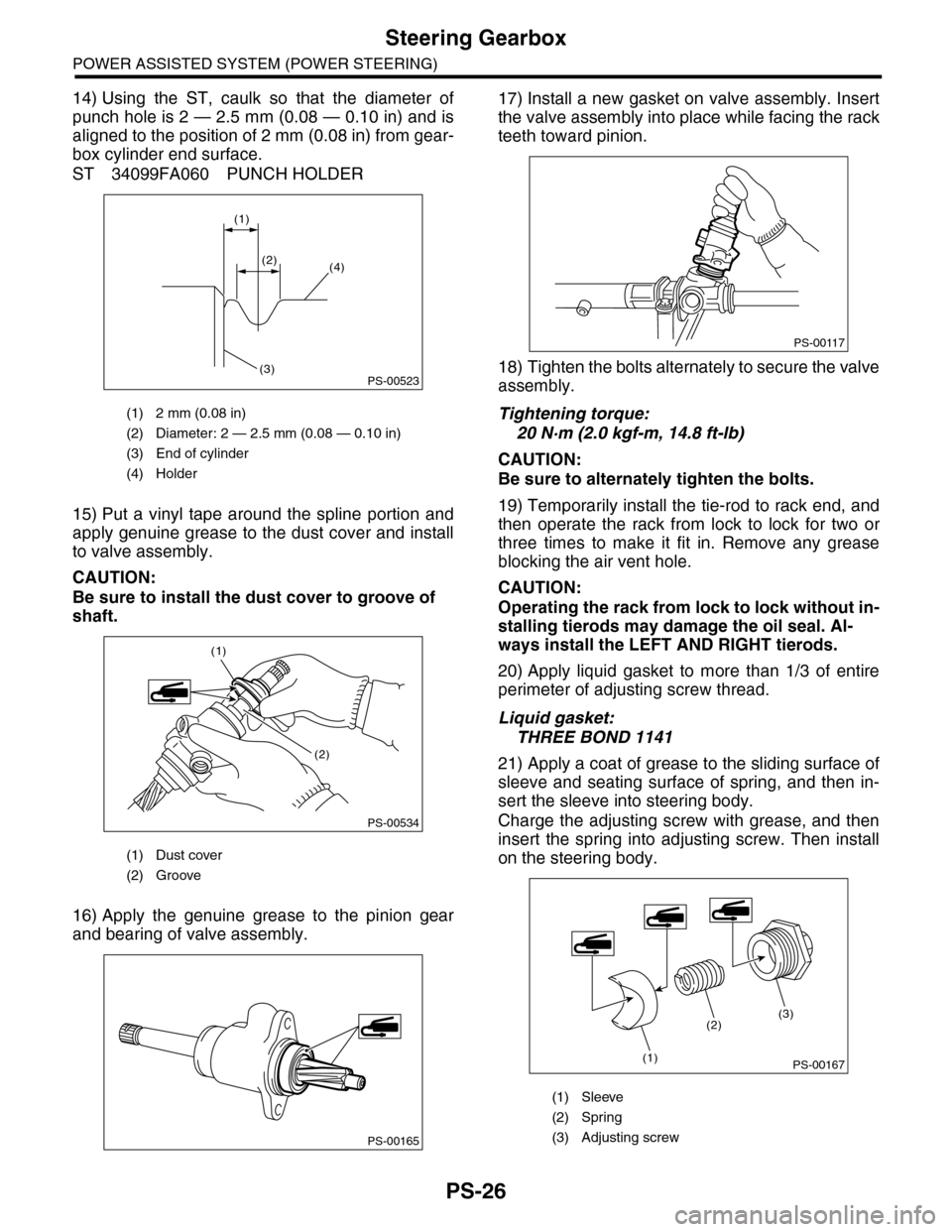
14) Using the ST, caulk so that the diameter of
punch hole is 2 — 2.5 mm (0.08 — 0.10 in) and is
aligned to the position of 2 mm (0.08 in) from gear-
box cylinder end surface.
ST 34099FA060 PUNCH HOLDER
15) Put a vinyl tape around the spline portion and
apply genuine grease to the dust cover and install
to valve assembly.
CAUTION:
Be sure to install the dust cover to groove of
shaft.
16) Apply the genuine grease to the pinion gear
and bearing of valve assembly.
17) Install a new gasket on valve assembly. Insert
the valve assembly into place while facing the rack
teeth toward pinion.
18) Tighten the bolts alternately to secure the valve
assembly.
Tightening torque:
20 N·m (2.0 kgf-m, 14.8 ft-lb)
CAUTION:
Be sure to alternately tighten the bolts.
19) Temporarily install the tie-rod to rack end, and
then operate the rack from lock to lock for two or
three times to make it fit in. Remove any grease
blocking the air vent hole.
CAUTION:
Operating the rack from lock to lock without in-
stalling tierods may damage the oil seal. Al-
ways install the LEFT AND RIGHT tierods.
20) Apply liquid gasket to more than 1/3 of entire
perimeter of adjusting screw thread.
Liquid gasket:
THREE BOND 1141
21) Apply a coat of grease to the sliding surface of
sleeve and seating surface of spring, and then in-
sert the sleeve into steering body.
Charge the adjusting screw with grease, and then
insert the spring into adjusting screw. Then install
on the steering body.
(1) 2 mm (0.08 in)
(2) Diameter: 2 — 2.5 mm (0.08 — 0.10 in)
(3) End of cylinder
(4) Holder
(1) Dust cover
(2) Groove
PS-00523
(1)
(2)(4)
(3)
PS-00534
(1)
(2)
PS-00165
(1) Sleeve
(2) Spring
(3) Adjusting screw
PS-00117
PS-00167
(2)
(1)
(3)
Page 911 of 2453
PS-31
Steering Gearbox
POWER ASSISTED SYSTEM (POWER STEERING)
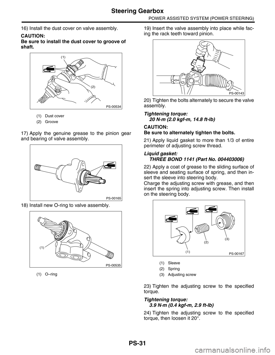
16) Install the dust cover on valve assembly.
CAUTION:
Be sure to install the dust cover to groove of
shaft.
17) Apply the genuine grease to the pinion gear
and bearing of valve assembly.
18) Install new O-ring to valve assembly.
19) Insert the valve assembly into place while fac-
ing the rack teeth toward pinion.
20) Tighten the bolts alternately to secure the valve
assembly.
Tightening torque:
20 N·m (2.0 kgf-m, 14.8 ft-lb)
CAUTION:
Be sure to alternately tighten the bolts.
21) Apply liquid gasket to more than 1/3 of entire
perimeter of adjusting screw thread.
Liquid gasket:
THREE BOND 1141 (Part No. 004403006)
22) Apply a coat of grease to the sliding surface of
sleeve and seating surface of spring, and then in-
sert the sleeve into steering body.
Charge the adjusting screw with grease, and then
insert the spring into adjusting screw. Then install
on the steering body.
23) Tighten the adjusting screw to the specified
torque.
Tightening torque:
3.9 N·m (0.4 kgf-m, 2.9 ft-lb)
24) Tighten the adjusting screw to the specified
torque, then loosen it 20°.
(1) Dust cover
(2) Groove
(1) O–ring
PS-00534
(1)
(2)
PS-00165
PS-00535
(1)
(1) Sleeve
(2) Spring
(3) Adjusting screw
PS-00143
PS-00167
(2)
(1)
(3)
Page 921 of 2453
PS-41
Oil Pump
POWER ASSISTED SYSTEM (POWER STEERING)
7. Oil Pump
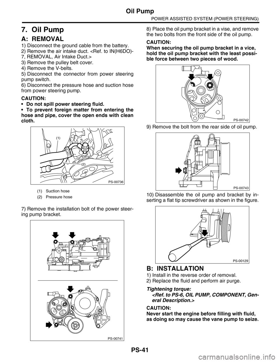
A: REMOVAL
1) Disconnect the ground cable from the battery.
2) Remove the air intake duct.
3) Remove the pulley belt cover.
4) Remove the V-belts.
5) Disconnect the connector from power steering
pump switch.
6) Disconnect the pressure hose and suction hose
from power steering pump.
CAUTION:
•Do not spill power steering fluid.
•To prevent foreign matter from entering the
hose and pipe, cover the open ends with clean
cloth.
7) Remove the installation bolt of the power steer-
ing pump bracket.
8) Place the oil pump bracket in a vise, and remove
the two bolts from the front side of the oil pump.
CAUTION:
When securing the oil pump bracket in a vice,
hold the oil pump bracket with the least possi-
ble force between two pieces of wood.
9) Remove the bolt from the rear side of oil pump.
10) Disassemble the oil pump and bracket by in-
serting a flat tip screwdriver as shown in the figure.
B: INSTALLATION
1) Install in the reverse order of removal.
2) Replace the fluid and perform air purge.
Tightening torque:
CAUTION:
Never start the engine before filling with fluid,
as doing so may cause the vane pump to seize.
(1) Suction hose
(2) Pressure hose
PS-00736
(1)
(2)
PS-00741
PS-00742
PS-00743
PS-00129
Page 924 of 2453

PS-44
Oil Pump
POWER ASSISTED SYSTEM (POWER STEERING)
E: INSPECTION
1. BASIC INSPECTION
Perform the following inspection procedures and replace faulty parts.
2. SERVICE LIMIT
Make a measurements as follows. If it exceeds the
service limit, replace with a new one.
CAUTION:
•When securing the oil pump on a vise, hold
the oil pump with the least possible force be-
tween two pieces of wood.
•Do not set the outside of flow control valve or
pulley on a vise; otherwise outside or pulley
might be deformed. Select properly sized wood
pieces.
1) Play of the pulley shaft
Condition:
P: When applying the force of 9.8 N (1.0 kgf,
2.2 lb)
Service limit:
Play in the radial direction (Direction )
Less than 0.2 mm (0.008 in)
Axial play (Direction )
Less than 0.6 mm (0.024 in)
2) Deflection of the pulley groove
Service limit:
Less than 1.0 mm (0.039 in)
NOTE:
Read the value for one surface of V ditch, and then
the value for another off the dial.
No. Parts Inspection Corrective action
1Oil pump
(Exterior)
(1) Crack, damage or oil leakage Replace the oil pump with a new one.
(2) Play of pulley shaft
Measure the radial play and axial play.
If any of these exceeds the service limit, replace the oil pump
with a new one.
2Pulley
(1) Damage Replace with a new part.
(2) BendMeasure the V groove deflection.
If it exceeds the service limit, replace the pulley with a new one.
3Oil pump
(Interior)
(1) Faulty or seized of vane pumpCheck the rotating resistance of pulley.
If it exceeds the service limit, replace the oil pump with new one.
(2) Bend in the shaft or damage
to bearing
If the a string is wrapped on the pulley and rotated, and the oil
pump emits a noise that is markedly different in tone and loud-
ness from a sound of a new oil pump, replace the oil pump with
a new one.
4O–ring Cracking or deterioration Replace with a new part.
5Bracket Cracking Replace with a new part.
(1) Dial gauge
PS-00145P
(1)
(1) Dial gauge
(1) Dial gauge
PS-00146P
(1)
PS-00147
Page 937 of 2453

RS-4
General Description
REAR SUSPENSION
2. SHOCK ABSORBER
C: CAUTION
Please understand and adhere to the following general precautions. They must be strictly followed to avoid
any injury to the person performing the work or persons in the area.
1. OPERATION
•Wear work clothing, including a cap, protective goggles and protective shoes during operation.
•Before disposing of shock absorbers, be sure to bleed the gas out completely. Also, do not expose to
flames or fire.
•Before removal, installation or disassembly, be sure to clarify the failure. Avoid unnecessary removal, in-
stallation, disassembly and replacement.
•Use SUBARU genuine grease etc. or equivalent. Do not mix grease etc. with that of another grade or from
other manufacturers.
•Before securing a part on a vise, place cushioning material such as wood blocks, aluminum plate, or cloth
between the part and the vise.
•Be sure to tighten fasteners including bolts and nuts to the specified torque.
•Place shop jacks or rigid racks at the specified points.
2. OIL
When handling oil, follow the rules below to prevent unexpected accidents.
•Prepare container and waste cloths when performing work which oil could possibly spill. If oil spills, wipe
it off immediately to prevent from penetrating into floor or flowing outside, for environmental protection.
•Follow all government regulations concerning disposal of refuse when disposing.
(1) Mount (5) Shock absorberTightening torque: N·m (kgf-m, ft-lb)
(2) Upper rubber sheet (6) Self–locking nutT1: 30 (3.1, 22.4)
(3) Dust cover T2: 35 (3.6, 26)
(4) Coil spring T3: 120 (12.2, 89)
Page 947 of 2453
RS-14
Front Lateral Link
REAR SUSPENSION
7. Front Lateral Link
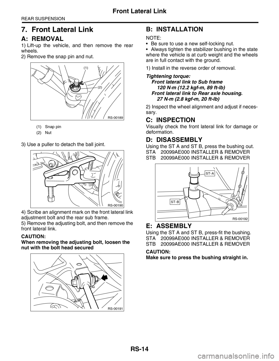
A: REMOVAL
1) Lift-up the vehicle, and then remove the rear
wheels.
2) Remove the snap pin and nut.
3) Use a puller to detach the ball joint.
4) Scribe an alignment mark on the front lateral link
adjustment bolt and the rear sub frame.
5) Remove the adjusting bolt, and then remove the
front lateral link.
CAUTION:
When removing the adjusting bolt, loosen the
nut with the bolt head secured
B: INSTALLATION
NOTE:
•Be sure to use a new self-locking nut.
•Always tighten the stabilizer bushing in the state
where the vehicle is at curb weight and the wheels
are in full contact with the ground.
1) Install in the reverse order of removal.
Tightening torque:
Front lateral link to Sub frame
120 N·m (12.2 kgf-m, 89 ft-lb)
Front lateral link to Rear axle housing.
27 N·m (2.8 kgf-m, 20 ft-lb)
2) Inspect the wheel alignment and adjust if neces-
sary.
C: INSPECTION
Visually check the front lateral link for damage or
deformation.
D: DISASSEMBLY
Using the ST A and ST B, press the bushing out.
STA 20099AE000 INSTALLER & REMOVER
STB 20099AE000 INSTALLER & REMOVER
E: ASSEMBLY
Using the ST A and ST B, press-fit the bushing.
STA 20099AE000 INSTALLER & REMOVER
STB 20099AE000 INSTALLER & REMOVER
CAUTION:
Make sure to press the bushing straight in.
(1) Snap pin
(2) Nut
RS-00189
(2)
(1)
RS-00190
RS-00191
RS-00192
ST-A
ST-B