Page 751 of 2453

BR-37
Stop Light Switch
BRAKE
15.Stop Light Switch
A: REMOVAL
1) Disconnect the ground cable from the battery.
2) Disconnect the stop light switch connector.
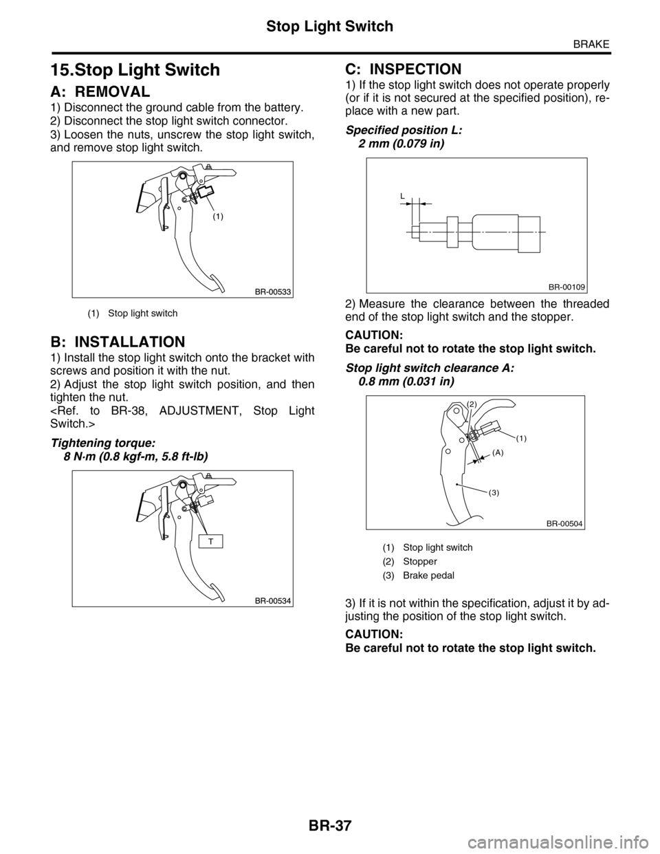
3) Loosen the nuts, unscrew the stop light switch,
and remove stop light switch.
B: INSTALLATION
1) Install the stop light switch onto the bracket with
screws and position it with the nut.
2) Adjust the stop light switch position, and then
tighten the nut.
Switch.>
Tightening torque:
8 N·m (0.8 kgf-m, 5.8 ft-lb)
C: INSPECTION
1) If the stop light switch does not operate properly
(or if it is not secured at the specified position), re-
place with a new part.
Specified position L:
2 mm (0.079 in)
2) Measure the clearance between the threaded
end of the stop light switch and the stopper.
CAUTION:
Be careful not to rotate the stop light switch.
Stop light switch clearance A:
0.8 mm (0.031 in)
3) If it is not within the specification, adjust it by ad-
justing the position of the stop light switch.
CAUTION:
Be careful not to rotate the stop light switch.
(1) Stop light switch
(1) Stop light switch
(2) Stopper
(3) Brake pedal
L
BR-00109
BR-00504
(1)
(3)
(2)
(A)
Page 780 of 2453
BVC(diag)-25
Diagnostic Procedure with Diagnostic Trouble Code (DTC)
BRAKE VACUUM CONTROL (BVC) (DIAGNOSTICS)
9CHECK BRAKE VACUUM PUMP.
1) Turn the ignition switch to OFF.
2) Remove the brake vacuum pump.
BR-39, REMOVAL, Brake Vacuum Pump.>
3) Connect the battery positive terminal to the
brake vacuum pump terminal No. 1, and the
negative terminal to terminal No. 2.
Is the brake vacuum pump
operating?
Go to step 10.Replace the brake
vacuum pump.
Brake Vacuum
Pump.>
10 CHECK BRAKE VACUUM PUMP.
1) Connect the brake vacuum pump relay.
2) Connect the connectors to the brake vac-
uum pump and ECM.
3) Turn the ignition switch to ON.
4) Execute the brake negative pressure pump
system function check mode using the Subaru
Select Monitor.
Select Monitor.>
Is the brake vacuum pump
operating?
Te m p o r a r y p o o r
contact occurs.
Replace the ECM.
FU(H6DO)-32,
Engine Control
Module (ECM).>
Step Check Yes No
Page 790 of 2453

DI-6
General Description
DIFFERENTIALS
C: CAUTION
•Wear work clothing, including a cap, protective goggles and protective shoes during operation.
•Remove contamination including dirt and corrosion before removal, installation or disassembly.
•Keep the disassembled parts in order and protect them from dust and dirt.
•Before removal, installation or disassembly, be sure to clarify the failure. Avoid unnecessary removal, in-
stallation, disassembly and replacement.
•Be careful not to burn yourself, because each part on the vehicle is hot after running.
•Use SUBARU genuine grease etc. or equivalent. Do not mix gear oil, grease, etc. with those of different
grades or from other manufacturers.
•Be sure to tighten fasteners including bolts and nuts to the specified torque.
•Place shop jacks or rigid racks at the specified points.
•Apply gear oil onto sliding or revolution surfaces before installation.
•Before installing the O-ring or snap ring, apply a sufficient amount of gear oil to avoid damage and defor-
mation.
•Before securing a part on a vise, place cushioning material such as wood blocks, aluminum plate, or cloth
between the part and the vise.
•Avoid damaging the mating surface of the case.
D: PREPARATION TOOL
1. SPECIAL TOOL
ILLUSTRATION TOOL NUMBER DESCRIPTION REMARKS
398477701 HANDLE Used for installing the front and rear bearing
cones.
398217700 ATTACHMENT SET Stand for rear differential carrier disassembly
and assembly.
498447120 INSTALLER Used for installing the front oil seal.
ST-398477701
ST-398217700
ST-498447120
Page 799 of 2453

DI-15
Rear Differential (VA–type)
DIFFERENTIALS
13) Remove the rear differential front member.
14) Secure the rear differential using band.
15) Remove the self-lock nuts which hold the rear
differential to rear crossmember.
16) Remove the air breather hose from the sub
frame.
17) Remove the rear differential stud bolt from rear
crossmember bushing.
NOTE:
When removing the stud bolt, carefully adjust the
angle and location of transmission jack and jack
stand, if necessary
18) Pull out the axle shaft from rear differential.
NOTE:
If it is difficult to remove the axle shaft from rear dif-
ferential, remove it using tire lever.
19) Lower the transmission jack.
20) Secure the rear drive shaft to lateral link using
wire.
21) Remove the rear differential member plate from
rear differential.
B: INSTALLATION
1) Insert the rear differential member plate into rear
differential.
2) Set the rear differential to transmission jack.
NOTE:
Secure the rear differential to transmission jack us-
ing band.
3) Install the ST to rear differential.
ST 28099PA090 OIL SEAL PROTECTOR
DI-00474
DI-00276
DI-00277
(A) Rear differential member plate
(A) Rear differential member plate
DI-00475
(A)
DI-00475
(A)
DI-00476
ST
Page 824 of 2453

DS-7
General Description
DRIVE SHAFT SYSTEM
C: CAUTION
Please clearly understand and adhere to the follow-
ing general precautions. They must be strictly fol-
lowed to avoid any injury to the person doing the
work or people in the area.
1. OPERATION
•Wear work clothing, including a cap, protective
goggles and protective shoes during operation.
•Remove contamination including dirt and corro-
sion before removal, installation or disassembly.
•Keep the disassembled parts in order and pro-
tect them from dust and dirt.
•Before removal, installation or disassembly, be
sure to clarify the failure. Avoid unnecessary re-
moval, installation, disassembly and replacement.
•Be careful not to burn yourself, because each
part on the vehicle is hot after running.
•Use SUBARU genuine grease etc. or equivalent.
Do not mix grease etc. with that of another grade or
from other manufacturers.
•Be sure to tighten fasteners including bolts and
nuts to the specified torque.
•Place shop jacks or rigid racks at the specified
points.
• Apply grease onto sliding or revolution surfaces
before installation.
•Before installing snap rings, apply sufficient
amount of grease to avoid damage and deforma-
tion.
•Before securing a part on a vise, place cushion-
ing material such as wood blocks, aluminum plate,
or shop cloth between the part and the vise.
2. OIL
When handling oil, follow the rules below to prevent
unexpected accidents.
•Prepare container and waste cloths when per-
forming work which oil could possibly spill. If oil
spills, wipe it off immediately to prevent from pene-
trating into floor or flowing outside, for environmen-
tal protection.
•Follow all government and local regulations con-
cerning waste disposal.
Page 830 of 2453

DS-13
Front Axle
DRIVE SHAFT SYSTEM
3. Front Axle
A: REMOVAL
1) Disconnect the ground cable from the battery.
2) Lift-up the vehicle, and remove the front wheels.
3) Lift the crimped section of axle nut.
4) Remove the axle nut using a socket wrench
while depressing the brake pedal.
CAUTION:
Remove the wheel before loosening the axle
nut. Failure to follow this rule may damage the
wheel bearings.
5) Remove the stabilizer link.
6) Remove the disc brake caliper from the front
housing, and suspend it from strut using a piece of
wire.
7) Remove the disc rotor from the hub.
NOTE:
If it is difficult to remove the disc rotor from the hub,
drive the 8 mm of bolt into the threaded end of rotor,
then remove the rotor.
8) Remove the cotter pin and castle nut securing
the tierod end to the front housing knuckle arm.
9) Using a puller, remove the tie–rod ball joint from
knuckle arm.
CAUTION:
When removing tie-rod, do not hit the tie-rod
end with hammer.
10) Remove the ABS wheel speed sensor assem-
bly and harness.
DS-00038
FS-00201
DS-00041
(A) Cotter pin
(B) Castle nut
(C) Tie–rod
DS-00042
(C)
(B)
(A)
DS-00043
DS-00249
Page 832 of 2453

DS-15
Front Axle
DRIVE SHAFT SYSTEM
10) While depressing the brake pedal, tighten a
new axle nut (olive color) to the specified torque
and lock it securely.
Tightening torque:
240 N·m (24.5 kgf-m, 177 ft-lb)
CAUTION:
•Install the wheel after installation of axle nut.
Failure to follow this rule may damage the
wheel bearing.
•Be sure to tighten the axle nut to specified
torque. Do not overtighten it as this may dam-
age the wheel bearing.
11) After tightening the axle nut, lock it securely.
12) Install the wheel and tighten the wheel nuts to
specified torque.
Tightening torque:
110 N·m (11.2 kgf-m, 81.1 ft-lb)
C: DISASSEMBLY
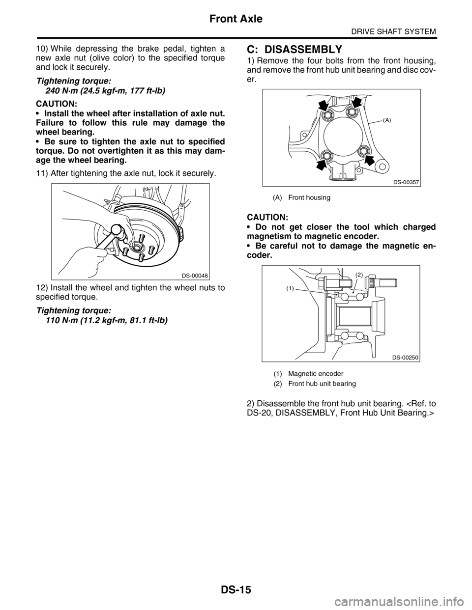
1) Remove the four bolts from the front housing,
and remove the front hub unit bearing and disc cov-
er.
CAUTION:
•Do not get closer the tool which charged
magnetism to magnetic encoder.
•Be careful not to damage the magnetic en-
coder.
2) Disassemble the front hub unit bearing.
DS-20, DISASSEMBLY, Front Hub Unit Bearing.>
DS-00048
(A) Front housing
(1) Magnetic encoder
(2) Front hub unit bearing
(A)
DS-00357
(2)
DS-00250
(1)
Page 837 of 2453

DS-20
Front Hub Unit Bearing
DRIVE SHAFT SYSTEM
B: INSTALLATION
1) Place the disc cover between front housing and
front hub unit, and tighten the four bolts.
Tightening torque:
65 N·m (6.6 kgf-m, 47.9 ft-lb)
2) Install the front drive shaft.
STALLATION, Front Drive Shaft.>
3) Tighten the axle nut temporarily.
4) Install the disc rotor to hub.
5) Install the disc brake caliper to the front housing.
Tightening torque:
120 N·m (12.2 kgf-m, 88.5 ft-lb)
6) While depressing the brake pedal, tighten a new
axle nut (olive color) to the specified torque and
lock it securely.
Tightening torque:
240 N·m (24.5 kgf-m, 177 ft-lb)
CAUTION:
•Install the wheel after installation of axle nut.
Failure to follow this rule may damage the
wheel bearing.
•Be sure to tighten the axle nut to specified
torque. Do not overtighten it as this may dam-
age the wheel bearing.
7) After tightening the axle nut, lock it securely.
8) Install the wheel and tighten the wheel nuts to
specified torque.
Tightening torque:
110 N·m (11.2 kgf-m, 81.1 ft-lb)
C: DISASSEMBLY
Using the ST and a hydraulic press, push out the
hub bolts.
ST 28399AG000 HUB STAND
CAUTION:
•Be careful not to hammer the hub bolts. This
may deform the hub.
•Do not reuse the hub bolt.
NOTE:
Since the hub unit bearing can not be disassem-
bled, only hub bolts can be removed.
D: ASSEMBLY
1) Attach the hub to the ST securely.
ST28099PA080 HUB STAND
2) Using a press, press the new hub bolts until their
seating surfaces contact the hub.
NOTE:
Use the 12 mm (0.47 in) dia. holes in the HUB
STAND to prevent bolts from tilting.
E: INSPECTION
Refer to Front Axle for inspection procedures.
CAUTION:
If there is any fault in the bearing, replace hub
unit bearing.
(A) Front housing
(A)
DS-00357
DS-00048
(1) Front hub unit bearing
(1) Front hub unit bearing
ST
DS-00252
(1)
DS-00253
ST
(1)