2009 SUBARU TRIBECA ECU
[x] Cancel search: ECUPage 952 of 2453

TPM(diag)-2
Basic Diagnostic Procedure
TIRE PRESSURE MONITORING SYSTEM (DIAGNOSTICS)
1. Basic Diagnostic Procedure
A: PROCEDURE
CAUTION:
Remove foreign matter (dust, water, oil etc.) from the tire pressure monitoring control module con-
nector when removing or installing.
NOTE:
To check harness for broken wires or short circuits, shake trouble spot or connector.
Step Check Yes No
1CHECK PRE-INSPECTION.
1) Check with the user regarding when the
warning light lit or started blinking.
2) Before performing diagnostics, check the
components which might mal-affect tire pres-
sure monitor system.
Is the component that might
affect the tire pressure monitor
system normal?
Go to step 2.Repair or replace
each component.
2CHECK DIAGNOSTIC TROUBLE CODE
(DTC).
1) Turn the ignition switch to OFF.
2) Connect the Subaru Select Monitor to data
link connector.
3) Turn the ignition switch to ON and Subaru
Select Monitor to ON.
NOTE:If the communication function of the Subaru Se-
lect Monitor cannot be executed normally,
check the communication circuit.
TIALIZING IMPOSSIBLE, INSPECTION, Sub-
aru Select Monitor.>
4) Read the DTC.
(DTC).>
Is DTC displayed? Go to step 4.Go to step 3.
3PERFORM GENERAL DIAGNOSTICS.
1) Inspect using “General Diagnostic Table”.
2) Perform the clear memory mode.
Subaru Select Monitor.>
3) Perform the inspection mode.
4) Read the DTC.
OPERATION, Subaru Select Monitor.>
Check the DTC is not displayed.
Does the tire pressure warn-
ing light illuminates for about 2
seconds and then foes off after
turning on the ignition switch,
and then go out?
Finish the diagno-
sis.
Check using
“Diagnostic Proce-
dure for TPM”
WITHOUT DTC,
INSPECTION,
Subaru Select
Monitor.>
4PERFORM DIAGNOSIS.
1) Refer to “List of Diagnostic Trouble Code
(DTC).”
2) Correct the cause of trouble.
3) Perform the clear memory mode.
Subaru Select Monitor.>
4) Perform the drive test.
Drive the vehicle at a speed more than 40 km/h
(25 MPH) for at least 10 minutes.
5) Read the DTC.
OPERATION, Subaru Select Monitor.>
Is DTC displayed? Repeat steps 1 to
4 until DTC is not
shown.
Finish the diagno-
sis.
Page 960 of 2453

TPM(diag)-10
Subaru Select Monitor
TIRE PRESSURE MONITORING SYSTEM (DIAGNOSTICS)
2) Connect the Subaru Select Monitor, on the
«Main Menu» display screen, select the {2. Each
System Check} and press the [YES] key.
3) On the «System Selection Menu» display
screen, select the {Tire Pressure Monitor} and
press the [YES] key.
4) Press the [YES] key after the {Tire Pressure
Monitor} is displayed.
5) On the «Tire Pressure Monitor Diagnosis» dis-
play screen, select the {Transmitter ID regist con-
firm} and press the [YES] key.
6) {When ID registration mode execute, Registered
ID is deleted Proceed?} is displayed then press the
[YES] key.
7) Touch the transmitter registration tool to the side
wall area near the air valve on the front left tire, and
press the switch. The transmitter ID is sent to the
tire pressure monitoring control module. (At that
time, the tire pressure warning light blinks to con-
firm that the registration has started.)
NOTE:
•Register the transmitter ID in the order of Left
Front → Right Front → Right Rear → Left Rear.
•The transmitter registration tool is used by touch-
ing the side wall area near the transmitter.
•When registration of each tire is completed, the
hazard light will blink and {ID registration complet-
ed} is displayed on the Select Monitor screen.
•If registration procedure stop in the halfway (turn-
ing ignition switch to OFF, wrong registration order,
etc), proceed from step 5)
8) When ID registration is completed, the tire pres-
sure warning light remains lit for approximately 2
seconds, to end the registration. Switch to the
screen displaying the transmitter ID on the Subaru
Select Monitor display.
Subaru Select Monitor.>
9) Check the transmitter ID that was registered,
then perform a driving test.
5. DISPLAY TRANSMITTER (ID).
1) On the «Main Menu» display screen, select the
{Each System Check} and press the [YES] key.
2) On the «System Selection Menu» display
screen, select the {Tire Pressure Monitor} and
press the [YES] key.
3) Press the [YES] key after the {Tire Pressure
Monitor} is displayed.
4) On the «Tire Pressure Monitor Diagnosis» dis-
play screen, select the {Transmitter ID regist con-
firm} and press the [YES] key.
5) Select {Transmitter ID Data Monitor} and press
the [YES] key to display the transmitter ID.
(1) Air valve (transmitter)
(2) Transmitter registration tool
(1)
(2)
TPM00006
Page 962 of 2453
TPM(diag)-12
Subaru Select Monitor
TIRE PRESSURE MONITORING SYSTEM (DIAGNOSTICS)
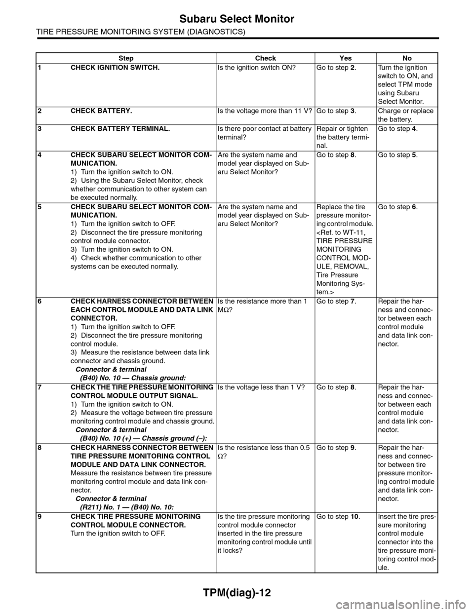
Step Check Yes No
1CHECK IGNITION SWITCH.Is the ignition switch ON? Go to step 2.Turn the ignition
switch to ON, and
select TPM mode
using Subaru
Select Monitor.
2CHECK BATTERY.Is the voltage more than 11 V? Go to step 3.Charge or replace
the battery.
3CHECK BATTERY TERMINAL.Is there poor contact at battery
terminal?
Repair or tighten
the battery termi-
nal.
Go to step 4.
4CHECK SUBARU SELECT MONITOR COM-
MUNICATION.
1) Turn the ignition switch to ON.
2) Using the Subaru Select Monitor, check
whether communication to other system can
be executed normally.
Are the system name and
model year displayed on Sub-
aru Select Monitor?
Go to step 8.Go to step 5.
5CHECK SUBARU SELECT MONITOR COM-
MUNICATION.
1) Turn the ignition switch to OFF.
2) Disconnect the tire pressure monitoring
control module connector.
3) Turn the ignition switch to ON.
4) Check whether communication to other
systems can be executed normally.
Are the system name and
model year displayed on Sub-
aru Select Monitor?
Replace the tire
pressure monitor-
ing control module.
MONITORING
CONTROL MOD-
ULE, REMOVAL,
Tire Pressure
Monitoring Sys-
tem.>
Go to step 6.
6CHECK HARNESS CONNECTOR BETWEEN
EACH CONTROL MODULE AND DATA LINK
CONNECTOR.
1) Turn the ignition switch to OFF.
2) Disconnect the tire pressure monitoring
control module.
3) Measure the resistance between data link
connector and chassis ground.
Connector & terminal
(B40) No. 10 — Chassis ground:
Is the resistance more than 1
MΩ?
Go to step 7.Repair the har-
ness and connec-
tor between each
control module
and data link con-
nector.
7CHECK THE TIRE PRESSURE MONITORING
CONTROL MODULE OUTPUT SIGNAL.
1) Turn the ignition switch to ON.
2) Measure the voltage between tire pressure
monitoring control module and chassis ground.
Connector & terminal
(B40) No. 10 (+) — Chassis ground (–):
Is the voltage less than 1 V? Go to step 8.Repair the har-
ness and connec-
tor between each
control module
and data link con-
nector.
8CHECK HARNESS CONNECTOR BETWEEN
TIRE PRESSURE MONITORING CONTROL
MODULE AND DATA LINK CONNECTOR.
Measure the resistance between tire pressure
monitoring control module and data link con-
nector.
Connector & terminal
(R211) No. 1 — (B40) No. 10:
Is the resistance less than 0.5
Ω?
Go to step 9.Repair the har-
ness and connec-
tor between tire
pressure monitor-
ing control module
and data link con-
nector.
9CHECK TIRE PRESSURE MONITORING
CONTROL MODULE CONNECTOR.
Tu r n t h e i g n i t i o n s w i t c h t o O F F.
Is the tire pressure monitoring
control module connector
inserted in the tire pressure
monitoring control module until
it locks?
Go to step 10.Insert the tire pres-
sure monitoring
control module
connector into the
tire pressure moni-
toring control mod-
ule.
Page 994 of 2453

VDC(diag)-2
Basic Diagnostic Procedure
VEHICLE DYNAMICS CONTROL (VDC) (DIAGNOSTICS)
1. Basic Diagnostic Procedure
A: PROCEDURE
NOTE:
•To check the harness for broken wires or short circuits, shake problem spot or connector.
•Refer to “Check List for Interview”.
Step Check Yes No
1CHECK PRE-INSPECTION.
1) Ask the customer when and how the trou-
ble occurred using the interview checklist.
2) Before performing diagnostics, check the
component which might affect VDC problems.
Is the component that might
influence the VDC problem
normal?
Go to step 2.Repair or replace
each component.
2CHECK INDICATION OF DTC.
1) Turn the ignition switch to OFF.
2) Connect the Subaru Select Monitor to data
link connector.
3) Turn the ignition switch to ON, and the Sub-
aru Select Monitor power switch to ON.
4) Read the DTC.
(DTC).>
NOTE:If the communication function of the Subaru Se-
lect Monitor cannot be executed normally,
check the communication circuit.
TIALIZING IMPOSSIBLE, INSPECTION, Sub-
aru Select Monitor.>
5) Record all DTCs and freeze frame data.
Is DTC displayed? Go to step 4.Go to step 3.
3PERFORM GENERAL DIAGNOSTICS.
1) Inspect using “General Diagnostic Table”.
2) Perform the clear memory mode.
Mode.>
3) Perform the inspection mode.
Mode.>
4) Read the DTC.
(DTC).>
5) Check the DTC is not displayed.
Do the VDC warning light and
ABS warning light go off after
starting the engine?
Finish the diagno-
sis.
Check the combi-
nation meter cir-
cuit.
ABS WARNING
LIGHT DOES NOT
GO OFF, Warning
Light Illumination
Patter n.>
VDC WARNING
LIGHT, TCS OFF
INDICATOR
LIGHT AND VDC
INDICATOR
LIGHT DO NOT
COME ON, Warn-
ing Light Illumina-
tion Pattern.>
Page 1012 of 2453
VDC(diag)-20
Subaru Select Monitor
VEHICLE DYNAMICS CONTROL (VDC) (DIAGNOSTICS)
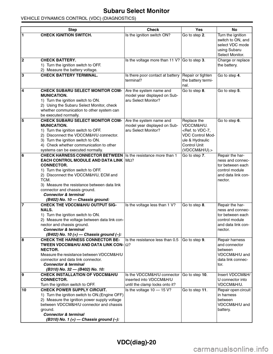
Step Check Yes No
1CHECK IGNITION SWITCH.Is the ignition switch ON? Go to step 2.Turn the ignition
switch to ON, and
select VDC mode
using Subaru
Select Monitor.
2CHECK BATTERY.
1) Turn the ignition switch to OFF.
2) Measure the battery voltage.
Is the voltage more than 11 V? Go to step 3.Charge or replace
the battery.
3CHECK BATTERY TERMINAL.Is there poor contact at battery
terminal?
Repair or tighten
the battery termi-
nal.
Go to step 4.
4CHECK SUBARU SELECT MONITOR COM-
MUNICATION.
1) Turn the ignition switch to ON.
2) Using the Subaru Select Monitor, check
whether communication to other system can
be executed normally.
Are the system name and
model year displayed on Sub-
aru Select Monitor?
Go to step 8.Go to step 5.
5CHECK SUBARU SELECT MONITOR COM-
MUNICATION.
1) Turn the ignition switch to OFF.
2) Disconnect the VDCCM&H/U connector.
3) Turn the ignition switch to ON.
4) Check whether communication to other
systems can be executed normally.
Are the system name and
model year displayed on Sub-
aru Select Monitor?
Replace the
VDCCM&H/U.
ule & Hydraulic
Control Unit
(VDCCM&H/U).>
Go to step 6.
6CHECK HARNESS CONNECTOR BETWEEN
EACH CONTROL MODULE AND DATA LINK
CONNECTOR.
1) Turn the ignition switch to OFF.
2) Disconnect the VDCCM&H/U, ECM and
TCM.
3) Measure the resistance between data link
connector and chassis ground.
Connector & terminal
(B402) No. 10 — Chassis ground:
Is the resistance more than 1
MΩ?
Go to step 7.Repair the har-
ness and connec-
tor between each
control module
and data link con-
nector.
7CHECK THE VDCCM&H/U OUTPUT SIG-
NALS.
1) Turn the ignition switch to ON.
2) Measure the voltage between data link con-
nector and chassis ground.
Connector & terminal
(B402) No. 10 (+) — Chassis ground (–):
Is the voltage less than 1 V? Go to step 8.Repair the har-
ness and connec-
tor between each
control module
and data link con-
nector.
8CHECK THE HARNESS CONNECTOR BE-
TWEEN VDCCM&H/U AND DATA LINK CON-
NECTOR.
Measure the resistance between VDCCM&H/U
connector and data link connector.
Connector & terminal
(B310) No. 32 — (B402) No. 10:
Is the resistance less than 0.5
Ω?
Go to step 9.Repair harness
and connector
between
VDCCM&H/U and
data link connec-
tor.
9CHECK INSTALLATION OF VDCCM&H/U
CONNECTOR.
Tu r n t h e i g n i t i o n s w i t c h t o O F F.
Is the VDCCM&H/U connector
inserted into VDCCM&H/U
until the clamp locks onto it?
Go to step 10.Insert VDCCM&H/
U connector into
VDCCM&H/U.
10 CHECK POWER SUPPLY CIRCUIT.
1) Turn the ignition switch to ON.(Engine OFF)
2) Measure the ignition power supply voltage
between VDCCM&H/U connector and chassis
ground.
Connector & terminal
(B310) No. 1 (+) — Chassis ground (–):
Is the voltage 10 — 15 V? Go to step 11.Repair open circuit
in harness
between
VDCCM&H/U and
battery.
Page 1093 of 2453
VDC-12
ABS Sequence Control
VEHICLE DYNAMICS CONTROL (VDC)
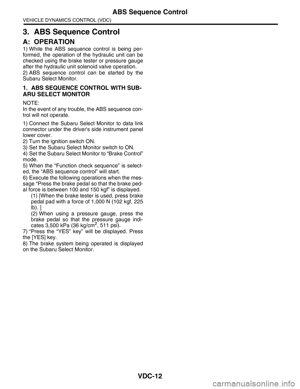
3. ABS Sequence Control
A: OPERATION
1) While the ABS sequence control is being per-
formed, the operation of the hydraulic unit can be
checked using the brake tester or pressure gauge
after the hydraulic unit solenoid valve operation.
2) ABS sequence control can be started by the
Subaru Select Monitor.
1. ABS SEQUENCE CONTROL WITH SUB-
ARU SELECT MONITOR
NOTE:
In the event of any trouble, the ABS sequence con-
trol will not operate.
1) Connect the Subaru Select Monitor to data link
connector under the driver's side instrument panel
lower cover.
2) Turn the ignition switch ON.
3) Set the Subaru Select Monitor switch to ON.
4) Set the Subaru Select Monitor to “Brake Control”
mode.
5) When the “Function check sequence” is select-
ed, the “ABS sequence control” will start.
6) Execute the following operations when the mes-
sage “Press the brake pedal so that the brake ped-
al force is between 100 and 150 kgf” is displayed.
(1) [When the brake tester is used, press brake
pedal pad with a force of 1,000 N (102 kgf, 225
lb). ]
(2) When using a pressure gauge, press the
brake pedal so that the pressure gauge indi-
cates 3,500 kPa (36 kg/cm2, 511 psi).
7) “Press the “YES” key” will be displayed. Press
the [YES] key.
8) The brake system being operated is displayed
on the Subaru Select Monitor.
Page 1100 of 2453
VDC-19
Steering Angle Sensor
VEHICLE DYNAMICS CONTROL (VDC)
6. Steering Angle Sensor
A: REPLACEMENT
CAUTION:
•Do not perform the removal except when the
replacement.
•When replacing more than three times, re-
place the combination switch as assembly to
protect the threads.
1) Set the steering wheel in a straight-ahead posi-
tion.
2) Disconnect the ground cable from the battery.
3) Remove the airbag module.
WARNING:
Always refer to “Airbag System” when perform-
ing the airbag module repair service.
4) Remove the steering wheel.
5) Remove the screws and remove the steering
column lower cover.
6) Remove the two screws securing the steering
column upper cover.
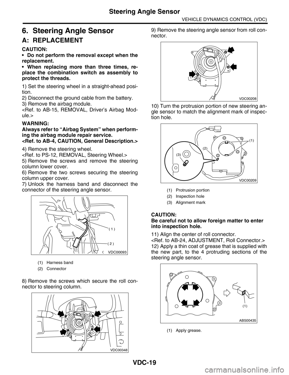
7) Unlock the harness band and disconnect the
connector of the steering angle sensor.
8) Remove the screws which secure the roll con-
nector to steering column.
9) Remove the steering angle sensor from roll con-
nector.
10) Turn the protrusion portion of new steering an-
gle sensor to match the alignment mark of inspec-
tion hole.
CAUTION:
Be careful not to allow foreign matter to enter
into inspection hole.
11) Align the center of roll connector.
12) Apply a thin coat of grease that is supplied with
the new part, to the 4 protruding sections of the
steering angle sensor.
(1) Harness band
(2) Connector
VDC00093
( 1 )
( 2 )
VDC00348
(1) Protrusion portion
(2) Inspection hole
(3) Alignment mark
(1) Apply grease.
VDC00208
VDC00209
(1)
(2)
(3)
ABS00435
(1)
Page 1102 of 2453
VDC-21
Front ABS Wheel Speed Sensor
VEHICLE DYNAMICS CONTROL (VDC)
7. Front ABS Wheel Speed Sen-
sor
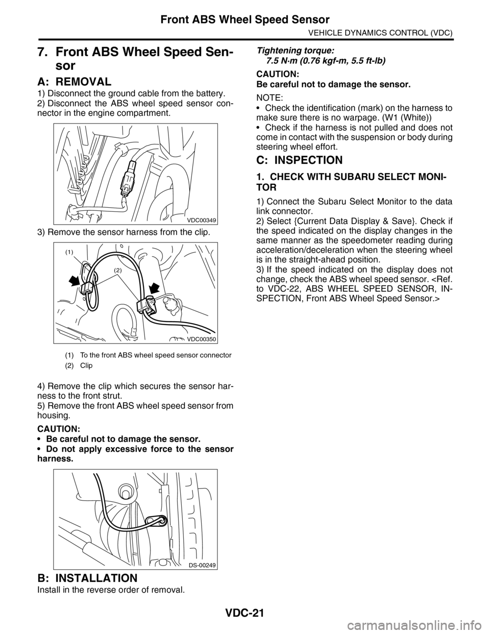
A: REMOVAL
1) Disconnect the ground cable from the battery.
2) Disconnect the ABS wheel speed sensor con-
nector in the engine compartment.
3) Remove the sensor harness from the clip.
4) Remove the clip which secures the sensor har-
ness to the front strut.
5) Remove the front ABS wheel speed sensor from
housing.
CAUTION:
•Be careful not to damage the sensor.
•Do not apply excessive force to the sensor
harness.
B: INSTALLATION
Install in the reverse order of removal.
Tightening torque:
7.5 N·m (0.76 kgf-m, 5.5 ft-lb)
CAUTION:
Be careful not to damage the sensor.
NOTE:
•Check the identification (mark) on the harness to
make sure there is no warpage. (W1 (White))
•Check if the harness is not pulled and does not
come in contact with the suspension or body during
steering wheel effort.
C: INSPECTION
1. CHECK WITH SUBARU SELECT MONI-
TOR
1) Connect the Subaru Select Monitor to the data
link connector.
2) Select {Current Data Display & Save}. Check if
the speed indicated on the display changes in the
same manner as the speedometer reading during
acceleration/deceleration when the steering wheel
is in the straight-ahead position.
3) If the speed indicated on the display does not
change, check the ABS wheel speed sensor.
SPECTION, Front ABS Wheel Speed Sensor.>
(1) To the front ABS wheel speed sensor connector
(2) Clip
VDC00349
VDC00350
(1)
(2)
DS-00249