2009 SUBARU TRIBECA ECU
[x] Cancel search: ECUPage 839 of 2453

DS-22
Rear Hub Unit Bearing
DRIVE SHAFT SYSTEM
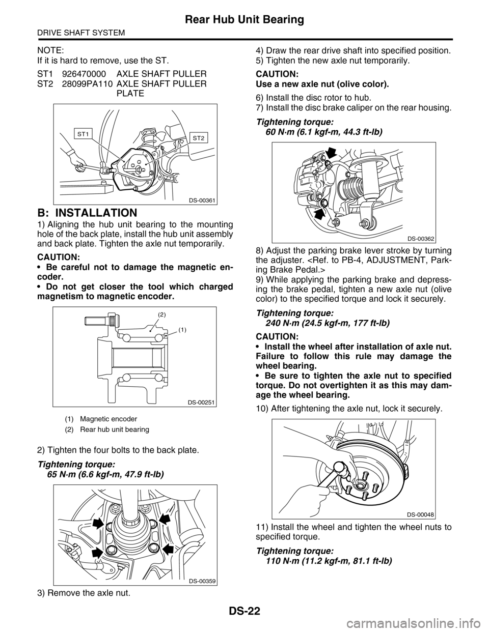
NOTE:
If it is hard to remove, use the ST.
ST1 926470000 AXLE SHAFT PULLER
ST2 28099PA110 AXLE SHAFT PULLER
PLATE
B: INSTALLATION
1) Aligning the hub unit bearing to the mounting
hole of the back plate, install the hub unit assembly
and back plate. Tighten the axle nut temporarily.
CAUTION:
•Be careful not to damage the magnetic en-
coder.
•Do not get closer the tool which charged
magnetism to magnetic encoder.
2) Tighten the four bolts to the back plate.
Tightening torque:
65 N·m (6.6 kgf-m, 47.9 ft-lb)
3) Remove the axle nut.
4) Draw the rear drive shaft into specified position.
5) Tighten the new axle nut temporarily.
CAUTION:
Use a new axle nut (olive color).
6) Install the disc rotor to hub.
7) Install the disc brake caliper on the rear housing.
Tightening torque:
60 N·m (6.1 kgf-m, 44.3 ft-lb)
8) Adjust the parking brake lever stroke by turning
the adjuster.
9) While applying the parking brake and depress-
ing the brake pedal, tighten a new axle nut (olive
color) to the specified torque and lock it securely.
Tightening torque:
240 N·m (24.5 kgf-m, 177 ft-lb)
CAUTION:
•Install the wheel after installation of axle nut.
Failure to follow this rule may damage the
wheel bearing.
•Be sure to tighten the axle nut to specified
torque. Do not overtighten it as this may dam-
age the wheel bearing.
10) After tightening the axle nut, lock it securely.
11) Install the wheel and tighten the wheel nuts to
specified torque.
Tightening torque:
110 N·m (11.2 kgf-m, 81.1 ft-lb)
(1) Magnetic encoder
(2) Rear hub unit bearing
ST2ST1
DS-00361
DS-00251
(2)
(1)
DS-00359
DS-00362
DS-00048
Page 840 of 2453

DS-23
Rear Hub Unit Bearing
DRIVE SHAFT SYSTEM
C: DISASSEMBLY
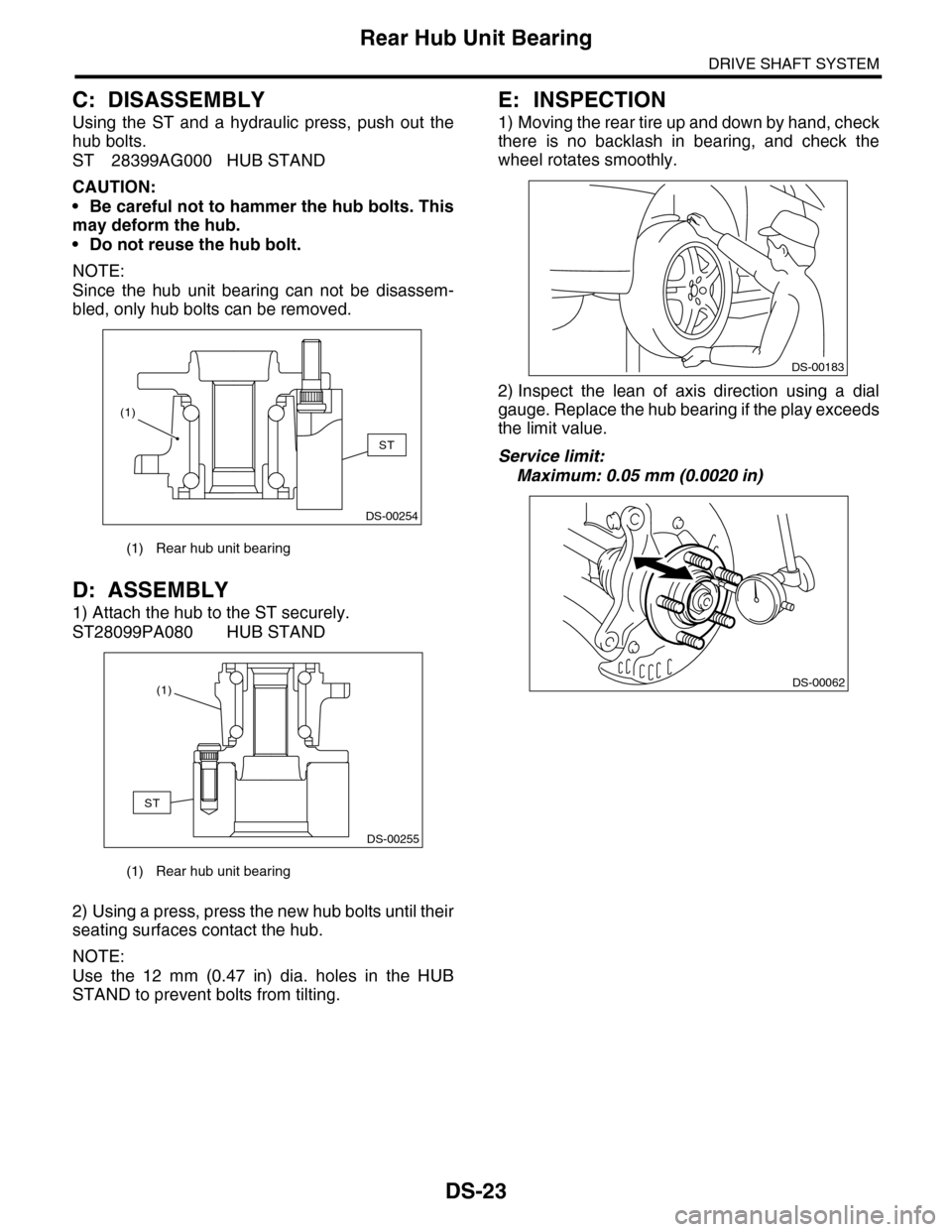
Using the ST and a hydraulic press, push out the
hub bolts.
ST 28399AG000 HUB STAND
CAUTION:
•Be careful not to hammer the hub bolts. This
may deform the hub.
•Do not reuse the hub bolt.
NOTE:
Since the hub unit bearing can not be disassem-
bled, only hub bolts can be removed.
D: ASSEMBLY
1) Attach the hub to the ST securely.
ST28099PA080 HUB STAND
2) Using a press, press the new hub bolts until their
seating surfaces contact the hub.
NOTE:
Use the 12 mm (0.47 in) dia. holes in the HUB
STAND to prevent bolts from tilting.
E: INSPECTION
1) Moving the rear tire up and down by hand, check
there is no backlash in bearing, and check the
wheel rotates smoothly.
2) Inspect the lean of axis direction using a dial
gauge. Replace the hub bearing if the play exceeds
the limit value.
Service limit:
Maximum: 0.05 mm (0.0020 in)
(1) Rear hub unit bearing
(1) Rear hub unit bearing
DS-00254
ST
(1)
DS-00255
ST
(1)
DS-00183
DS-00062
Page 842 of 2453

DS-25
Front Drive Shaft
DRIVE SHAFT SYSTEM
8) While depressing the brake pedal, tighten a new
axle nut (olive color) to the specified torque and
lock it securely.
Tightening torque:
240 N·m (24.5 kgf-m, 177 ft-lb)
CAUTION:
•Install the wheel after installation of axle nut.
Failure to follow this rule may damage the
wheel bearing.
•Be sure to tighten axle nut to specified
torque. Do not overtighten it as this may dam-
age the wheel bearing.
9) After tightening axle nut, lock it securely.
C: DISASSEMBLY
1) Place alignment marks on the shaft and outer
race.
2) Remove the PTJ boot band and boot.
CAUTION:
Be careful not to damage the boot.
3) Remove the snap ring from PTJ outer race.
4) Remove the PTJ outer race from shaft assem-
bly.
5) Wipe off grease.
CAUTION:
The grease is a special type of grease. Do not
mix with other grease.
6) Place alignment marks on the roller kit and trun-
nion.
7) Remove the roller kit from trunnion.
CAUTION:
Be careful with the roller kit position.
8) Place alignment marks on the trunnion and
shaft.
DS-00106
DS-00107
DS-00108
DS-00109
DS-00110
Page 844 of 2453

DS-27
Front Drive Shaft
DRIVE SHAFT SYSTEM
11) Put a new band through the clip and wind twice
in the band groove of the boot.
12) Pinch the end of band with pliers. Hold the clip
and tighten securely.
NOTE:
When tightening boot, use care so that the air with-
in the boot is appropriate.
13) Tighten the band using the ST.
ST 925091000 BAND TIGHTENING TOOL
NOTE:
Tighten the band until it cannot be moved by hand.
14) Tap the clip with the punch provided at the end
of the ST.
ST 925091000 BAND TIGHTENING TOOL
CAUTION:
Tap to an extent that the boot underneath is not
damaged.
15) Cut off the band with an allowance of about 10
mm (0.39 in) left from the clip and bend this allow-
ance over the clip.
CAUTION:
Make sure that the end of the band is in close
contact with clip.
16) Extend and retract the PTJ to provide equal
grease coating.
E: INSPECTION
Check the removed parts for damage, wear, corro-
sion etc. If faulty, repair or replace.
•PTJ (pillow tripod joint)
Check for seizure, corrosion, damage, wear and
excessive play.
•EBJ (high-efficiency compact ball fixed joint)
Check for seizure, corrosion, damage and exces-
sive play.
•Shaft
Check for excessive bending, twisting, damage
and wear.
•Boot
Check for wear, warping, breakage and scratches.
•Grease
Check for discoloration and fluidity.
DS-00132
DS-00133
Page 845 of 2453

DS-28
Rear Drive Shaft
DRIVE SHAFT SYSTEM
8. Rear Drive Shaft
A: REMOVAL
1) Disconnect the ground cable from the battery.
2) Lift-up the vehicle, and then remove the rear
wheels.
3) Lift the crimped section of axle nut.
4) While applying the parking brake, remove the
axle nut using a socket wrench.
CAUTION:
Remove the wheel before loosening the axle
nut. Failure to follow this rule may damage the
wheel bearings.
5) Remove the rear differential assembly.
VA-type
6) Remove the axle nut and rear drive shaft. If it is
hard to remove, use ST1 and ST2.
ST1 926470000 AXLE SHAFT PULLER
ST2 28099PA110 AXLE SHAFT PULLER
PLATE
CAUTION:
•Do not hammer drive shaft when removing.
•Do not damage the oil seal and magnetic en-
coder.
B: INSTALLATION
1) Insert the EBJ into hub splines.
CAUTION:
•Be careful not to damage the magnetic en-
coder.
•Do not get closer the tool which charged
magnetism to magnetic encoder.
2) Draw the rear drive shaft into specified position.
CAUTION:
Do not hammer drive shaft when installing it.
3) Tighten the axle nut temporarily.
4) Install the rear differential assembly.
VA-type
5) While applying the parking brake and depress-
ing the brake pedal, tighten a new axle nut (olive
color) to the specified torque and lock it securely.
Tightening torque:
240 N·m (24.5 kgf-m, 177 ft-lb)
CAUTION:
•Install the wheel after installation of axle nut.
Failure to follow this rule may damage the
wheel bearing.
•Be sure to tighten the axle nut to specified
torque. Do not overtighten it as this may dam-
age the wheel bearing.
6) Lock the axle nut securely.
DS-00038
DS-00122
ST2ST1
(1) Magnetic encoder
(2) Rear hub unit bearing
DS-00251
(2)
(1)
DS-00048
Page 848 of 2453

DS-31
Rear Drive Shaft
DRIVE SHAFT SYSTEM
10) Install the snap ring in the groove on the DOJ
outer race.
NOTE:
•Assure that the balls, cage and inner race are
completely fitted in the outer race of DOJ.
•Use care not to place the matched position of
snap ring in the ball groove of outer race.
•Pull the shaft lightly and assure that the circlip is
completely fitted in the groove.
11) Apply an even coat of the specified grease [20
to 30 g (0. 71 to 1. 06 oz)] to the entire inner surface
of boot. Also apply grease to the shaft.
12) Install the DOJ boot taking care not to twist it.
NOTE:
•The inside of the larger end of DOJ boot and the
boot groove shall be cleaned so as to be free from
grease and other substances.
•When installing the DOJ boot, position the outer
race of DOJ at center of the stroke.
13) Put a new band through the clip and wind twice
in the band groove of the boot.
14) Pinch the end of band with pliers. Hold the clip
and tighten securely.
NOTE:
When tightening boot, use care so that the air with-
in the boot is appropriate.
15) Tighten the band using the ST.
ST 925091000 BAND TIGHTENING TOOL
NOTE:
Tighten the band until it cannot be moved by hand.
16) Tap the clip with the punch provided at the end
of the ST.
ST 925091000 BAND TIGHTENING TOOL
NOTE:
Tap to an extent that the boot underneath is not
damaged.
17) Cut off the band with an allowance of about 10
mm (0.39 in) left from the clip and bend this allow-
ance over the clip.
NOTE:
Be careful so that the end of the band is in close
contact with clip.
18) Install the EBJ boot using the same procedures
as for the DOJ boot.
19) Extend and retract the DOJ repeatedly to pro-
vide an equal coating of grease.
E: INSPECTION
Check the removed parts for damage, wear, corro-
sion etc. Repair or replace if defective.
•DOJ (Double Offset Joint)
Check for seizure, corrosion, damage, wear and
excessive play.
•EBJ (high-efficiency compact ball fixed joint)
Check for seizure, corrosion, damage, wear and
excessive play.
•Shaft
Check for excessive bending, twisting, damage
and wear.
•Boot
Check for wear, warping, breakage and scratches.
•Grease
Check for discoloration and fluidity.
DS-00125
DS-00132
DS-00133
Page 852 of 2453

FS-4
General Description
FRONT SUSPENSION
C: CAUTION
Please understand and adhere to the following general precautions. They must be strictly followed to avoid
any injury to the person performing the work or persons in the area.
1. OPERATION
•Wear work clothing, including a cap, protective goggles and protective shoes during operation.
•Before removal, installation or disassembly, be sure to clarify the failure. Avoid unnecessary removal, in-
stallation, disassembly and replacement.
•Use SUBARU genuine grease etc. or equivalent. Do not mix grease etc. with that of another grade or from
other manufacturers.
•Before securing a part on a vise, place cushioning material such as wood blocks, aluminum plate, or cloth
between the part and the vise.
•Be sure to tighten fasteners including bolts and nuts to the specified torque.
•Place shop jacks or rigid racks at the specified points.
2. OIL
When handling oil, follow the rules below to prevent unexpected accidents.
•Prepare container and waste cloths when performing work which oil could possibly spill. If oil spills, wipe
it off immediately to prevent from penetrating into floor or flowing outside, for environmental protection.
•Follow all government and local regulations concerning waste disposal.
D: PREPARATION TOOL
1. SPECIAL TOOL
ILLUSTRATION TOOL NUMBER DESCRIPTION REMARKS
927680000 INSTALLER &
REMOVER SET
Used for replacing front arm front bushing.
20299AG000 REMOVER Used for replacing front arm rear bushing.
Used with BASE (20999AG010).
ST-927680000
ST20299AG000
Page 864 of 2453

FS-16
Front Arm
FRONT SUSPENSION
6. Front Arm
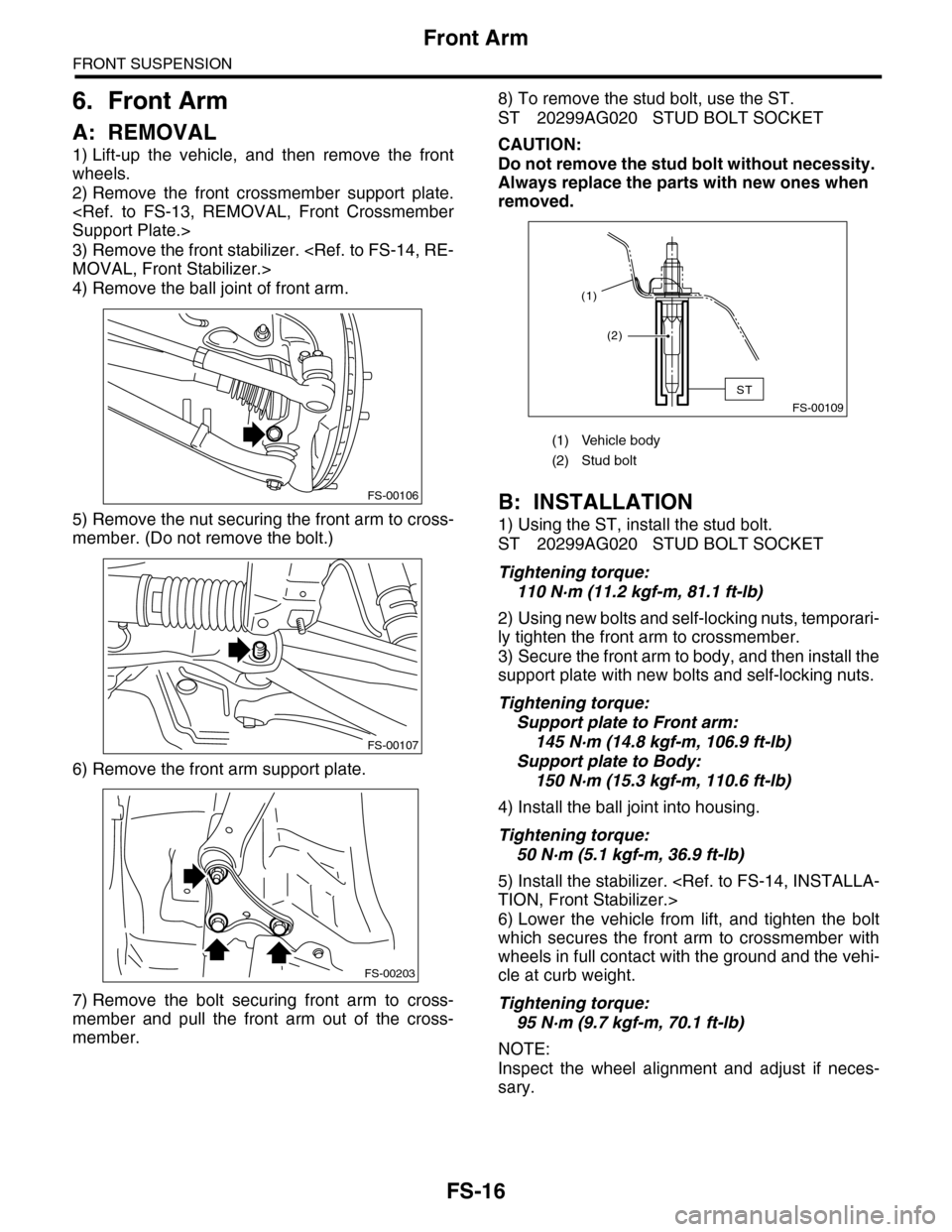
A: REMOVAL
1) Lift-up the vehicle, and then remove the front
wheels.
2) Remove the front crossmember support plate.
3) Remove the front stabilizer.
4) Remove the ball joint of front arm.
5) Remove the nut securing the front arm to cross-
member. (Do not remove the bolt.)
6) Remove the front arm support plate.
7) Remove the bolt securing front arm to cross-
member and pull the front arm out of the cross-
member.
8) To remove the stud bolt, use the ST.
ST 20299AG020 STUD BOLT SOCKET
CAUTION:
Do not remove the stud bolt without necessity.
Always replace the parts with new ones when
removed.
B: INSTALLATION
1) Using the ST, install the stud bolt.
ST 20299AG020 STUD BOLT SOCKET
Tightening torque:
110 N·m (11.2 kgf-m, 81.1 ft-lb)
2) Using new bolts and self-locking nuts, temporari-
ly tighten the front arm to crossmember.
3) Secure the front arm to body, and then install the
support plate with new bolts and self-locking nuts.
Tightening torque:
Support plate to Front arm:
145 N·m (14.8 kgf-m, 106.9 ft-lb)
Support plate to Body:
150 N·m (15.3 kgf-m, 110.6 ft-lb)
4) Install the ball joint into housing.
Tightening torque:
50 N·m (5.1 kgf-m, 36.9 ft-lb)
5) Install the stabilizer.
6) Lower the vehicle from lift, and tighten the bolt
which secures the front arm to crossmember with
wheels in full contact with the ground and the vehi-
cle at curb weight.
Tightening torque:
95 N·m (9.7 kgf-m, 70.1 ft-lb)
NOTE:
Inspect the wheel alignment and adjust if neces-
sary.
FS-00106
FS-00107
FS-00203
(1) Vehicle body
(2) Stud bolt
FS-00109
(2)
(1)
ST