Page 1093 of 2453
VDC-12
ABS Sequence Control
VEHICLE DYNAMICS CONTROL (VDC)
3. ABS Sequence Control
A: OPERATION
1) While the ABS sequence control is being per-
formed, the operation of the hydraulic unit can be
checked using the brake tester or pressure gauge
after the hydraulic unit solenoid valve operation.
2) ABS sequence control can be started by the
Subaru Select Monitor.
1. ABS SEQUENCE CONTROL WITH SUB-
ARU SELECT MONITOR
NOTE:
In the event of any trouble, the ABS sequence con-
trol will not operate.
1) Connect the Subaru Select Monitor to data link
connector under the driver's side instrument panel
lower cover.
2) Turn the ignition switch ON.
3) Set the Subaru Select Monitor switch to ON.
4) Set the Subaru Select Monitor to “Brake Control”
mode.
5) When the “Function check sequence” is select-
ed, the “ABS sequence control” will start.
6) Execute the following operations when the mes-
sage “Press the brake pedal so that the brake ped-
al force is between 100 and 150 kgf” is displayed.
(1) [When the brake tester is used, press brake
pedal pad with a force of 1,000 N (102 kgf, 225
lb). ]
(2) When using a pressure gauge, press the
brake pedal so that the pressure gauge indi-
cates 3,500 kPa (36 kg/cm2, 511 psi).
7) “Press the “YES” key” will be displayed. Press
the [YES] key.
8) The brake system being operated is displayed
on the Subaru Select Monitor.
Page 1096 of 2453
VDC-15
VDC Sequence Control
VEHICLE DYNAMICS CONTROL (VDC)
4. VDC Sequence Control
A: OPERATION
1) While the VDC sequence control is performed,
the operation of the hydraulic unit can be checked
using the brake tester or pressure gauge after the
hydraulic unit solenoid valve is operated.
2) VDC sequence control can be started by Subaru
Select Monitor.
1. VDC SEQUENCE CONTROL WITH SUB-
ARU SELECT MONITOR
NOTE:
In the event of any trouble, sequence control will
not operate.
1) Connect the Subaru Select Monitor to data link
connector under the driver's side instrument panel
lower cover.
2) Turn the ignition switch ON.
3) Set the Subaru Select Monitor switch to ON.
4) Set the Subaru Select Monitor to “Brake Control”
mode.
5) When the “VDC Inspection Mode” is selected
from the “Function check sequence” menu, the
“VDC sequence control” will start.
6) ”Press the “YES” key” will be displayed. Press
the [YES] key.
7) Operation points will be displayed on Subaru Se-
lect Monitor.
Page 1102 of 2453
VDC-21
Front ABS Wheel Speed Sensor
VEHICLE DYNAMICS CONTROL (VDC)
7. Front ABS Wheel Speed Sen-
sor
A: REMOVAL
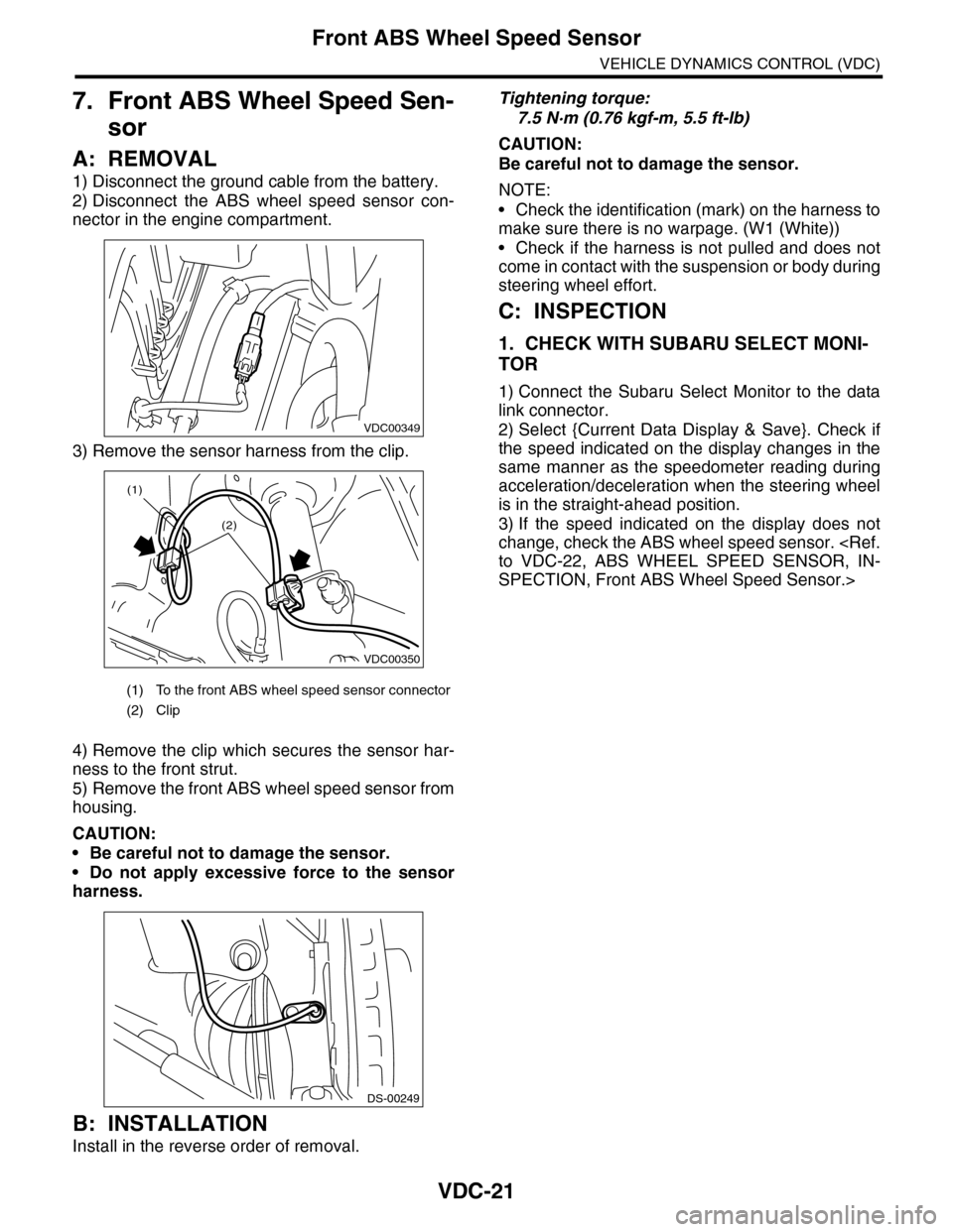
1) Disconnect the ground cable from the battery.
2) Disconnect the ABS wheel speed sensor con-
nector in the engine compartment.
3) Remove the sensor harness from the clip.
4) Remove the clip which secures the sensor har-
ness to the front strut.
5) Remove the front ABS wheel speed sensor from
housing.
CAUTION:
•Be careful not to damage the sensor.
•Do not apply excessive force to the sensor
harness.
B: INSTALLATION
Install in the reverse order of removal.
Tightening torque:
7.5 N·m (0.76 kgf-m, 5.5 ft-lb)
CAUTION:
Be careful not to damage the sensor.
NOTE:
•Check the identification (mark) on the harness to
make sure there is no warpage. (W1 (White))
•Check if the harness is not pulled and does not
come in contact with the suspension or body during
steering wheel effort.
C: INSPECTION
1. CHECK WITH SUBARU SELECT MONI-
TOR
1) Connect the Subaru Select Monitor to the data
link connector.
2) Select {Current Data Display & Save}. Check if
the speed indicated on the display changes in the
same manner as the speedometer reading during
acceleration/deceleration when the steering wheel
is in the straight-ahead position.
3) If the speed indicated on the display does not
change, check the ABS wheel speed sensor.
to VDC-22, ABS WHEEL SPEED SENSOR, IN-
SPECTION, Front ABS Wheel Speed Sensor.>
(1) To the front ABS wheel speed sensor connector
(2) Clip
VDC00349
VDC00350
(1)
(2)
DS-00249
Page 1110 of 2453
WT-4
General Description
WHEEL AND TIRE SYSTEM
B: COMPONENT
1. TIRE PRESSURE MONITORING SYSTEM
(1) Transmitter (4) CapTightening torque: N·m (kgf-m, ft-lb)
(2) Grommet (5) Tire pressure monitoring control
module
T1: 7.5 (0.76, 5.53)
(3) NutT2: 8 (0.8, 5.8)
WT-00069
(4)
(3)
(2)
(1)
T1
T2
T2
(5)
Page 1112 of 2453
WT-6
Tire
WHEEL AND TIRE SYSTEM
2. Tire
A: INSPECTION
1) Take stones, glass, nails etc. out of the tread
groove.
2) Replace tires in the following cases.
CAUTION:
•When replacing a tire, make sure to use only
tires of the same size, construction and load
range as originally installed.
•Use a tire changer when removing the tire
from the wheel.
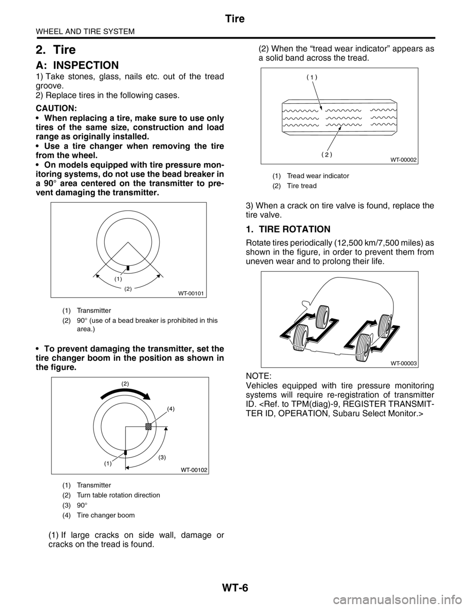
•On models equipped with tire pressure mon-
itoring systems, do not use the bead breaker in
a 90° area centered on the transmitter to pre-
vent damaging the transmitter.
•To prevent damaging the transmitter, set the
tire changer boom in the position as shown in
the figure.
(1) If large cracks on side wall, damage or
cracks on the tread is found.
(2) When the “tread wear indicator” appears as
a solid band across the tread.
3) When a crack on tire valve is found, replace the
tire valve.
1. TIRE ROTATION
Rotate tires periodically (12,500 km/7,500 miles) as
shown in the figure, in order to prevent them from
uneven wear and to prolong their life.
NOTE:
Vehicles equipped with tire pressure monitoring
systems will require re-registration of transmitter
ID.
TER ID, OPERATION, Subaru Select Monitor.>
(1) Transmitter
(2) 90° (use of a bead breaker is prohibited in this
area.)
(1) Transmitter
(2) Turn table rotation direction
(3) 90°
(4) Tire changer boom
(1)
WT-00101(2)
(1) Tread wear indicator
(2) Tire tread
WT-00002
WT-00003
Page 1116 of 2453
WT-10
“T–type” Tire
WHEEL AND TIRE SYSTEM
5. “T–type” Tire
A: NOTE
“T–type” tire for temporary use is equipped as a
spare tire.
CAUTION:
•Do not drive at a speed greater than 100 km/h
(62 MPH).
•For the model with tire pressure monitoring
system, the indicator light may blink when run-
ning with the “T-type” tire.
B: REPLACEMENT
Refer to Aluminum Wheels for removal and instal-
lation procedures of the “T–type”.
REMOVAL, Aluminum Wheel.>
CAUTION:
The “T–type” tire is only for temporary use. Re-
place with a conventional tire as soon as possi-
ble.
C: INSPECTION
1) Check the tire air pressure.
Specifications:
420 kPa (4.2 kg/cm2, 60 psi)
2) Take stones, glass, nails, etc. out of the tread
groove.
3) Check the tires for deformation, cracks, partial
wear, or wear.
CAUTION:
Replace the tire with a new one if defective.
Page 1117 of 2453
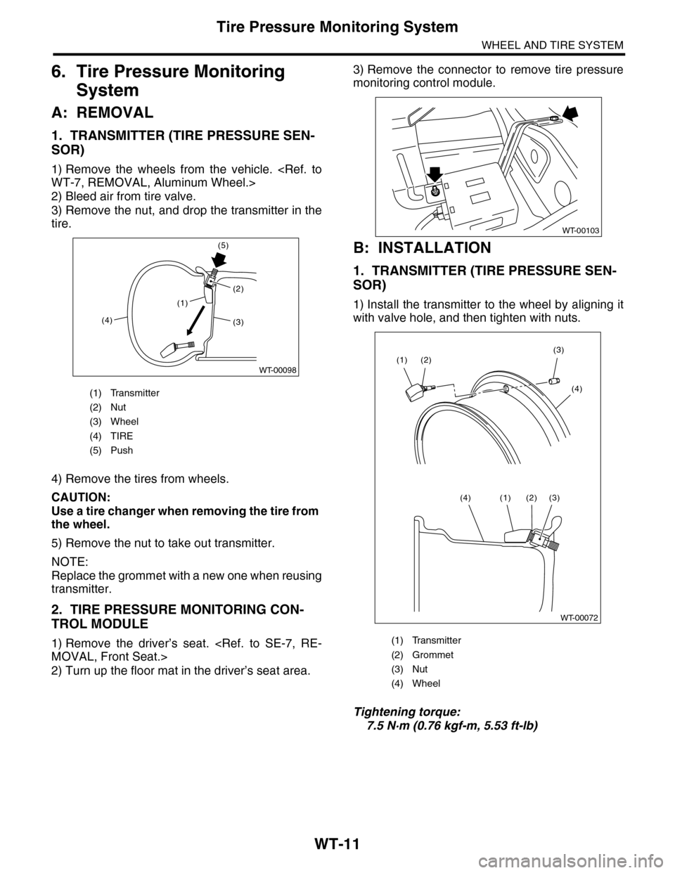
WT-11
Tire Pressure Monitoring System
WHEEL AND TIRE SYSTEM
6. Tire Pressure Monitoring
System
A: REMOVAL
1. TRANSMITTER (TIRE PRESSURE SEN-
SOR)
1) Remove the wheels from the vehicle.
WT-7, REMOVAL, Aluminum Wheel.>
2) Bleed air from tire valve.
3) Remove the nut, and drop the transmitter in the
tire.
4) Remove the tires from wheels.
CAUTION:
Use a tire changer when removing the tire from
the wheel.
5) Remove the nut to take out transmitter.
NOTE:
Replace the grommet with a new one when reusing
transmitter.
2. TIRE PRESSURE MONITORING CON-
TROL MODULE
1) Remove the driver’s seat.
MOVAL, Front Seat.>
2) Turn up the floor mat in the driver’s seat area.
3) Remove the connector to remove tire pressure
monitoring control module.
B: INSTALLATION
1. TRANSMITTER (TIRE PRESSURE SEN-
SOR)
1) Install the transmitter to the wheel by aligning it
with valve hole, and then tighten with nuts.
Tightening torque:
7.5 N·m (0.76 kgf-m, 5.53 ft-lb)
(1) Transmitter
(2) Nut
(3) Wheel
(4) TIRE
(5) Push
(1)
(4)
(5)
(2)
WT-00098
(3)
(1) Transmitter
(2) Grommet
(3) Nut
(4) Wheel
WT-00103
WT-00072
(2)(3)
(4)
(1)
(3)(2)(1)(4)
Page 1118 of 2453
WT-12
Tire Pressure Monitoring System
WHEEL AND TIRE SYSTEM
2) Install the tires to wheels.
CAUTION:
•Use a tire changer when installing tire to
wheel.
•To prevent damaging the transmitter, set the
tire changer boom in the position as shown in
the figure.
3) Install the wheels to vehicle.
STALLATION, Aluminum Wheel.>
4) Register the transmitter ID to the tire pressure
monitoring control module.
REGISTER TRANSMITTER ID, OPERATION,
Subaru Select Monitor.>
2. TIRE PRESSURE MONITORING CON-
TROL MODULE
Install in the reverse order of removal.
Tightening torque:
8 N·m (0.8 kgf-m, 5.8 ft-lb)
C: ADJUSTMENT
Re-register the transmitter ID when transmitter has
been replaced or tires have been rotated.
TPM(diag)-9, REGISTER TRANSMITTER ID, OP-
ERATION, Subaru Select Monitor.>
(1) Transmitter
(2) Turn table rotation direction
(3) 90°
(4) Tire changer boom