Page 216 of 2453
ET-31
Rear Accessory Power Supply Socket
ENTERTAINMENT
26.Rear Accessory Power Sup-
ply Socket
A: REMOVAL
1) Disconnect the ground cable from battery.
2) Remove the console box.
MOVAL, Center Console.>
3) Disconnect the harness connector, and remove
the accessory power supply socket.
NOTE:
The socket can be pulled out by unlocking the ac-
cessory socket lock in 2 locations and turning the
socket to the left.
B: INSTALLATION
Install in the reverse order of removal.
NOTE:
Confirm that the accessory socket is locked and
can not be pulled out.
ET-00191
(A)
Page 233 of 2453

EB-14
Front Hood
EXTERIOR BODY PANELS
4) Remove the front fender.
MOVAL, Front Fender.>
5) Remove the bolts of front hood hinge.
5. FRONT HOOD STRIKER
Refer to the front hood lock assembly of SL section.
Assembly.>
6. FRONT HOOD PANEL
1) Remove the front hood insulator.
2) Open the front hood to remove the window
washer hose.
3) Remove the front hood weather strip.
4) Remove the hood lock assembly.
sembly.>
5) Remove the window washer hose and nozzle.
zle.>
6) Remove the front hood damper.
7) Remove the bolt, and remove the front hood
panel from the front hood hinge.
B: INSTALLATION
Install in the reverse order of removal.
NOTE:
Be careful not to catch the window washer hose in.
Tightening torque:
Refer to “COMPONENT” of “General Descrip-
tion”.
NENT, General Description.>
C: ADJUSTMENT
1) Adjust the clearance between front hood panel
and front fender panel. Clearance must be equal at
both sides. For the dimension of clearance, refer to
“SPECIFICATION” in “General Description”.
to EB-2, SPECIFICATION, General Description.>
2) Use the hinge mounting bolts to align the front
hood longitudinal and lateral position.
3) Adjust the height at the front end of hood.
to SL-44, ADJUSTMENT, Front Hood Lock Assem-
bly.>
4) Rotate the hood buffer to adjust lateral height.
D: DISPOSAL
For the disposal procedures of front hood damper
stay, refer to the disposal procedures of rear gate
damper stay.
Gate.>
EB-00286
EB-00285
EB-00285
EB-00287
Page 235 of 2453

EB-16
Front Door
EXTERIOR BODY PANELS
4. Front Door
A: REMOVAL
1) Disconnect the ground cable from battery.
2) Remove the front door trim.
MOVAL, Door Trim.>
3) Remove the outer mirror assembly.
GW-13, REMOVAL, Outer Mirror Assembly.>
4) Remove the front door speaker.
REMOVAL, Front Speaker.>
5) Remove the sealing cover.
MOVAL, Front Sealing Cover.>
6) Remove the front door glass.
REMOVAL, Front Door Glass.>
7) Remove the door sash, and remove the front
door regulator and motor assemblies.
10, REMOVAL, Front Regulator and Motor Assem-
bly.>
8) Remove the front inner remote.
REMOVAL, Front Inner Remote.>
9) Remove the front door latch assembly.
SL-36, REMOVAL, Front Door Latch and Door
Lock Actuator Assembly.>
10) Remove the front outer handle.
REMOVAL, Front Outer Handle.>
11) Remove the front door weather strip.
NOTE:
If the weather strip clip is removed with excessive
force, the weather strip may be damaged. Be sure
to use clip remover to remove.
12) Remove the bolts and nuts to remove the door
checker.
13) Remove the instrument panel lower cover or
glove box lower cover.
Instrument Panel Lower Cover.> or
REMOVAL, Glove Box.>
14) Disconnect the connector of door harness from
body harness.
15) Put a wooden block on jack and place jack un-
der the front door. Support the door with a jack to
protect it from damage.
16) Remove the door-side bolts for upper and low-
er hinges to remove front door panel.
17) Remove the door hinge from vehicle.
EB-00141
EB-00154
EB-00151
EB-00013
EB-00015
Page 236 of 2453

EB-17
Front Door
EXTERIOR BODY PANELS
B: INSTALLATION
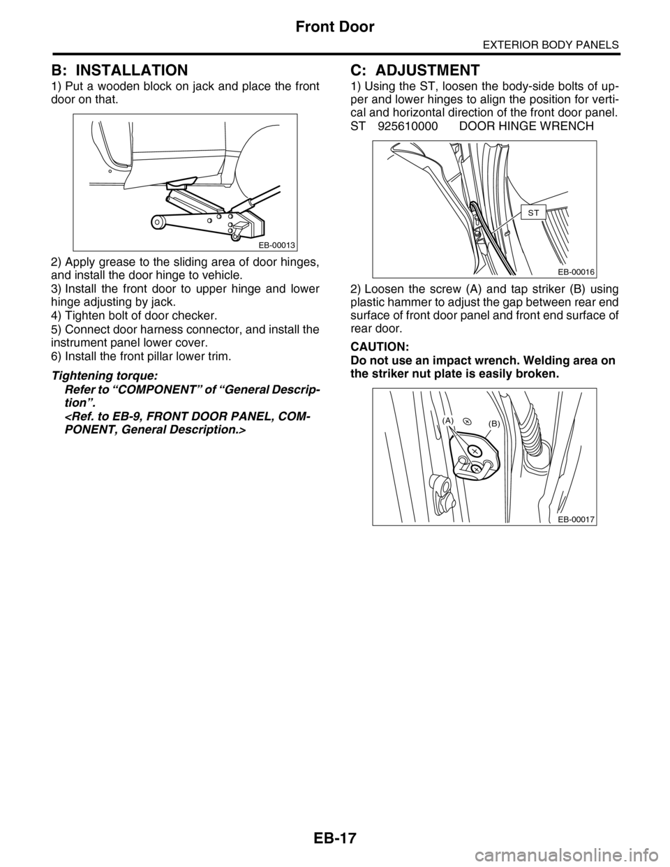
1) Put a wooden block on jack and place the front
door on that.
2) Apply grease to the sliding area of door hinges,
and install the door hinge to vehicle.
3) Install the front door to upper hinge and lower
hinge adjusting by jack.
4) Tighten bolt of door checker.
5) Connect door harness connector, and install the
instrument panel lower cover.
6) Install the front pillar lower trim.
Tightening torque:
Refer to “COMPONENT” of “General Descrip-
tion”.
PONENT, General Description.>
C: ADJUSTMENT
1) Using the ST, loosen the body-side bolts of up-
per and lower hinges to align the position for verti-
cal and horizontal direction of the front door panel.
ST 925610000 DOOR HINGE WRENCH
2) Loosen the screw (A) and tap striker (B) using
plastic hammer to adjust the gap between rear end
surface of front door panel and front end surface of
rear door.
CAUTION:
Do not use an impact wrench. Welding area on
the striker nut plate is easily broken.
EB-00013
EB-00016
ST
EB-00017
(B)(A)
Page 238 of 2453

EB-19
Rear Door
EXTERIOR BODY PANELS
6. Rear Door
A: REMOVAL
1) Disconnect the ground cable from battery.
2) Remove the rear door trim.
MOVAL, Door Trim.>
3) Remove the rear speaker.
MOVAL, Rear Speaker.>
4) Remove the sealing cover.
MOVAL, Rear Sealing Cover.>
5) Remove the rear door glass.
REMOVAL, Rear Door Glass.>
6) Remove the door sash and rear door regulator
and motor assemblies.
AL, Rear Regulator and Motor Assembly.>
7) Remove the rear inner remote.
REMOVAL, Rear Inner Remote.>
8) Remove the rear door latch.
MOVAL, Rear Door Latch and Door Lock Actuator
Assembly.>
9) Remove the rear outer handle.
REMOVAL, Rear Outer Handle.>
10) Remove the rear door inner weather strip.
NOTE:
If the weather strip clip is removed with excessive
force, the weather strip may be damaged. Be sure
to use clip remover to remove.
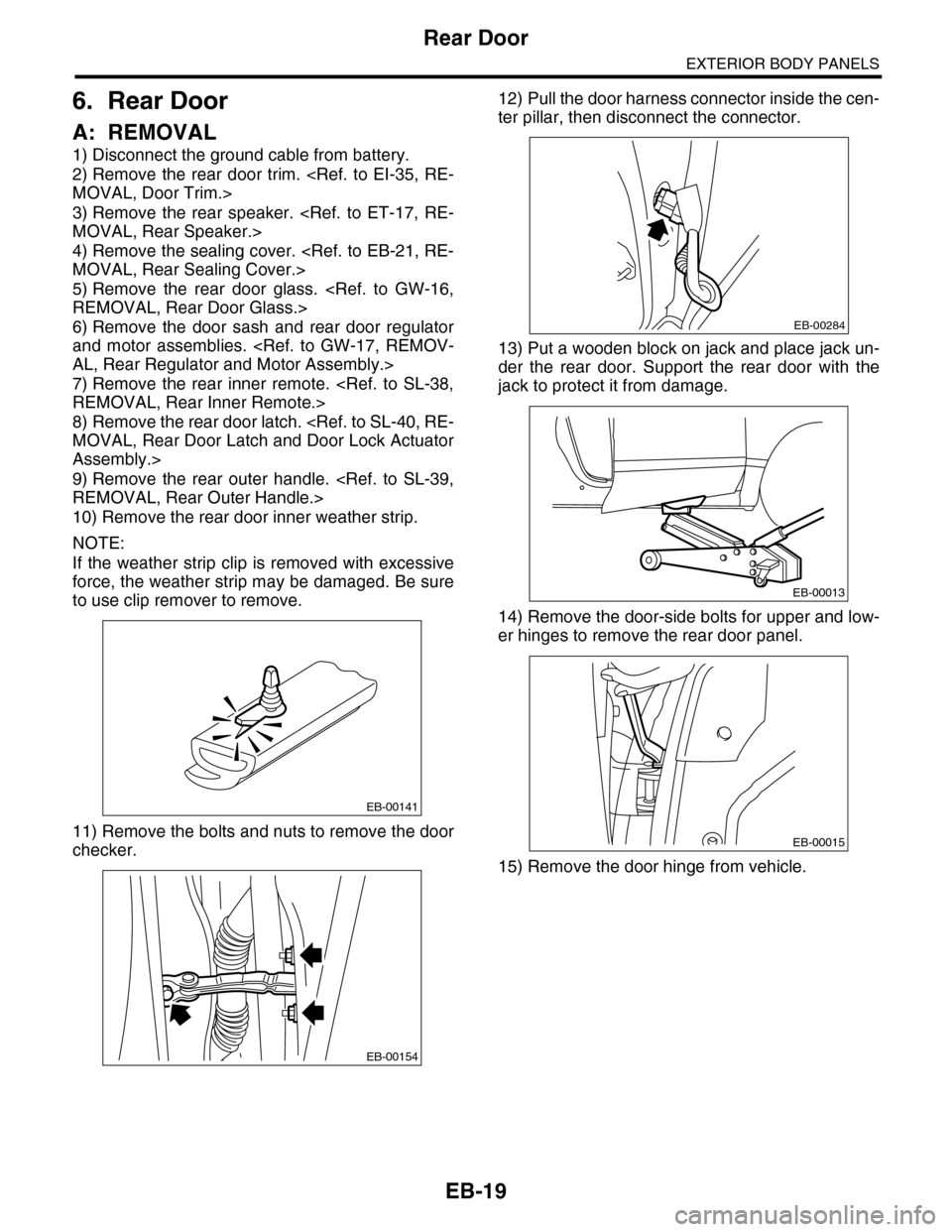
11) Remove the bolts and nuts to remove the door
checker.
12) Pull the door harness connector inside the cen-
ter pillar, then disconnect the connector.
13) Put a wooden block on jack and place jack un-
der the rear door. Support the rear door with the
jack to protect it from damage.
14) Remove the door-side bolts for upper and low-
er hinges to remove the rear door panel.
15) Remove the door hinge from vehicle.
EB-00141
EB-00154
EB-00284
EB-00013
EB-00015
Page 239 of 2453
EB-20
Rear Door
EXTERIOR BODY PANELS
B: INSTALLATION
1) Put a wooden block on jack and place the rear
door on that.
2) Apply grease to the moving part of door hinges.
3) Install the rear door to upper hinge and lower
hinge adjusting by jack.
4) Tighten bolt of door checker.
5) Connect the door harness connector.
Tightening torque:
Refer to “COMPONENT” of “General Descrip-
tion”.
PONENT, General Description.>
C: ADJUSTMENT
1) Open the rear door, loosen the door-side bolts of
upper and lower hinges to align the position for ver-
tical and horizontal direction of rear door panel.
2) Loosen the screw (A) and tap striker (B) using
plastic hammer to adjust the gap between rear end
surface of rear door panel and body surface.
CAUTION:
Do not use an impact wrench. Welding area on
the striker nut plate is easily broken.
EB-00013
EB-00015
EB-00017
(B)(A)
Page 265 of 2453

EI-23
Front Bumper
EXTERIOR/INTERIOR TRIM
C: REPAIR
1. COATING METHOD FOR PP BUMPER
Process
No.Process name Job contents
1Bumper installation
Place the bumper on a paint worktable as
required. Use the paint worktable conforming
to inner shape of bumper if possible.
(1) Bumper
(2) Set bumper section
2MaskingMask specified part (black base) with masking tape. Use masking tape for PP (example,
Nichiban No. 533, etc. ).
3Degreasing/cleaningClean all parts to be painted with white gasoline, normal alcohol, etc. to remove dirt, oil, fat, etc.
4Primer paint Apply primer to all parts to be painted, using spray gun. Use primer (clear).
5Drying
Dry at normal temperature [10 — 15 min. at 20°C (68°F)].
In half-dried condition, PP primer paint is dissolved by solvent, e.g. thinner, etc.
Therefore, if dust or dirt must be removed, use ordinary alcohol etc.
6Top coat paint (I)
Non-colored Metallic paint
Use section (block) paint for top coat.
•Paint to be used (for each color):
Solid paint
Hardener PB
Thinner T-301
•Mixture ratio:
Main agent vs. hardener = 4:1
• Viscosity: 10 — 13 sec./20°C (68°F)
•Film thickness: 35 — 45 µ
•Spraying pressure: 245 — 343 kPa
(2.5 — 3.5 kg/cm2, 36 — 50 psi)
Use section (block) paint for top coat.
•Paint to be used (for each color):
Metallic paint
Hardener PB
Thinner T-306
•Mixture ratio:
Main agent vs. hardener = 10:1
•Viscosity: 10 — 13 sec./20°C (68°F)
•Film thickness: 15 — 20 µ
•Spraying pressure: 245 — 343 kPa
(2.5 — 3.5 kg/cm2, 36 — 50 psi)
7Drying Not required.
Dry at normal temperature [at least 10 min. at
20°C (68°F)].
In half-dried condition, avoid dust, dirt.
8Top coat paint (II)Not required.
Apply a clear coat to parts with top coat paint
(I), three times at 5 — 7 minutes intervals.
•Paint to be used:
Metallic paint
Hardener PB
Thinner T-301
•Mixture ratio:
Clear coat vs. hardener = 6:1
•Viscosity: 14 — 16 sec./20°C (68°F)
•Film thickness: 25 — 30 µ
•Spraying pressure: 245 — 343 kPa
(2.5 — 3.5 kg/cm2, 36 — 50 psi)
9Drying
60°C (140°F), 60 min. or 80°C (176°F), 30 min.
If higher than 80°C (176°F), PP may become be deformed. Keep maximum temperature below
80°C (176°F).
10 Inspection Check paint.
11 Removal of masking Remove the masking tape applied in procedure 2.
EI-00234(2)
(1)
Page 269 of 2453

EI-27
Front Bumper
EXTERIOR/INTERIOR TRIM
18Cleaning/degreas-
ingSame as Process No. 12.
19 Top coat (I)
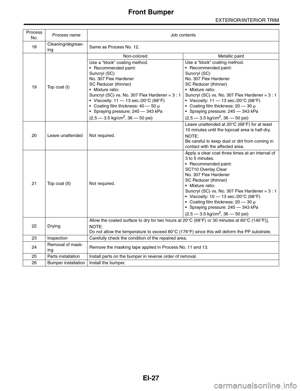
Non-colored Metallic paint
Use a “block” coating method.
•Recommended paint:
Suncryl (SC)
No. 307 Flex Hardener
SC Reducer (thinner)
•Mixture ratio:
Suncryl (SC) vs. No. 307 Flex Hardener = 3 : 1
•Viscosity: 11 — 13 sec./20°C (68°F)
• Coating film thickness: 40 — 50 µ
•Spraying pressure: 245 — 343 kPa
(2.5 — 3.5 kg/cm2, 36 — 50 psi)
Use a “block” coating method.
•Recommended paint:
Suncryl (SC)
No. 307 Flex Hardener
SC Reducer (thinner)
•Mixture ratio:
Suncryl (SC) vs. No. 307 Flex Hardener = 3 : 1
•Viscosity: 11 — 13 sec./20°C (68°F)
•Coating film thickness: 20 — 30 µ
•Spraying pressure: 245 — 343 kPa
(2.5 — 3.5 kg/cm2, 36 — 50 psi)
20 Leave unattended Not required.
Leave unattended at 20°C (68°F) for at least
10 minutes until the topcoat area is half-dry.
NOTE:
Be careful to keep dust or dirt from coming in
contact with the affected area.
21 Top coat (II) Not required.
Apply a clear coat three times at an interval of
3 to 5 minutes.
•Recommended paint:
SC710 Overlay Clear
No. 307 Flex Hardener
SC Reducer (thinner)
•Mixture ratio:
Suncryl (SC) vs. No. 307 Flex Hardener = 3 : 1
•Viscosity: 10 — 13 sec./20°C (68°F)
•Coating film thickness: 20 — 30 µ
•Spraying pressure: 245 — 343 kPa
(2.5 — 3.5 kg/cm2, 36 — 50 psi)
22 Drying
Allow the coated surface to dry for two hours at 20°C (68°F) or 30 minutes at 60°C (140°F)].
NOTE:Do not allow the temperature to exceed 80°C (176°F) since this will deform the PP substrate.
23 Inspection Carefully check the condition of the repaired area.
24Removal of mask-
ingRemove the masking tape applied in Process No. 11 and 13.
25 Parts installation Install parts on the bumper in reverse order of removal.
26 Bumper installation Install the bumper.
Process
No.Process name Job contents