Page 291 of 2453
EI-49
Assist Grip
EXTERIOR/INTERIOR TRIM
22.Assist Grip
A: REMOVAL
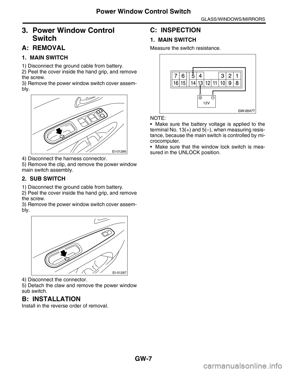
1) Remove the screw cover, and remove the screw
inside.
2) Pull the left side of assist grip toward you, and ro-
tate the right side of it counterclockwise to remove.
3) Remove the roof trim.
AL, Roof Trim.>
4) Remove the bolts, and remove the assist grip
bracket.
B: INSTALLATION
Install in the reverse order of removal.
CAUTION:
Be sure to install the grommet to assist grip
bracket.
When the assist grip is installed with no grom-
met, it ill cause the grip to not return properly.
(A) Grommet
EI-00809
EI-01065
(A)
Page 301 of 2453
GW-6
Power Window System
GLASS/WINDOWS/MIRRORS
2. Power Window System
A: WIRING DIAGRAM
B: INSPECTION
Symptom Repair order
All power windows do not operate.
1. Fuse (SBF-4)
2. Power window circuit breaker
3. Power window relay
4. Wiring Harness
5. Body integrated unit
Par ticular window does not operate.
1. Power window main switch
2. Power window sub switch
3. Power window motor
4. Wiring Harness
“Window Lock” does not operate. Power window main switch
Page 302 of 2453

GW-7
Power Window Control Switch
GLASS/WINDOWS/MIRRORS
3. Power Window Control
Switch
A: REMOVAL
1. MAIN SWITCH
1) Disconnect the ground cable from battery.
2) Peel the cover inside the hand grip, and remove
the screw.
3) Remove the power window switch cover assem-
bly.
4) Disconnect the harness connector.
5) Remove the clip, and remove the power window
main switch assembly.
2. SUB SWITCH
1) Disconnect the ground cable from battery.
2) Peel the cover inside the hand grip, and remove
the screw.
3) Remove the power window switch cover assem-
bly.
4) Disconnect the connector.
5) Detach the claw and remove the power window
sub switch.
B: INSTALLATION
Install in the reverse order of removal.
C: INSPECTION
1. MAIN SWITCH
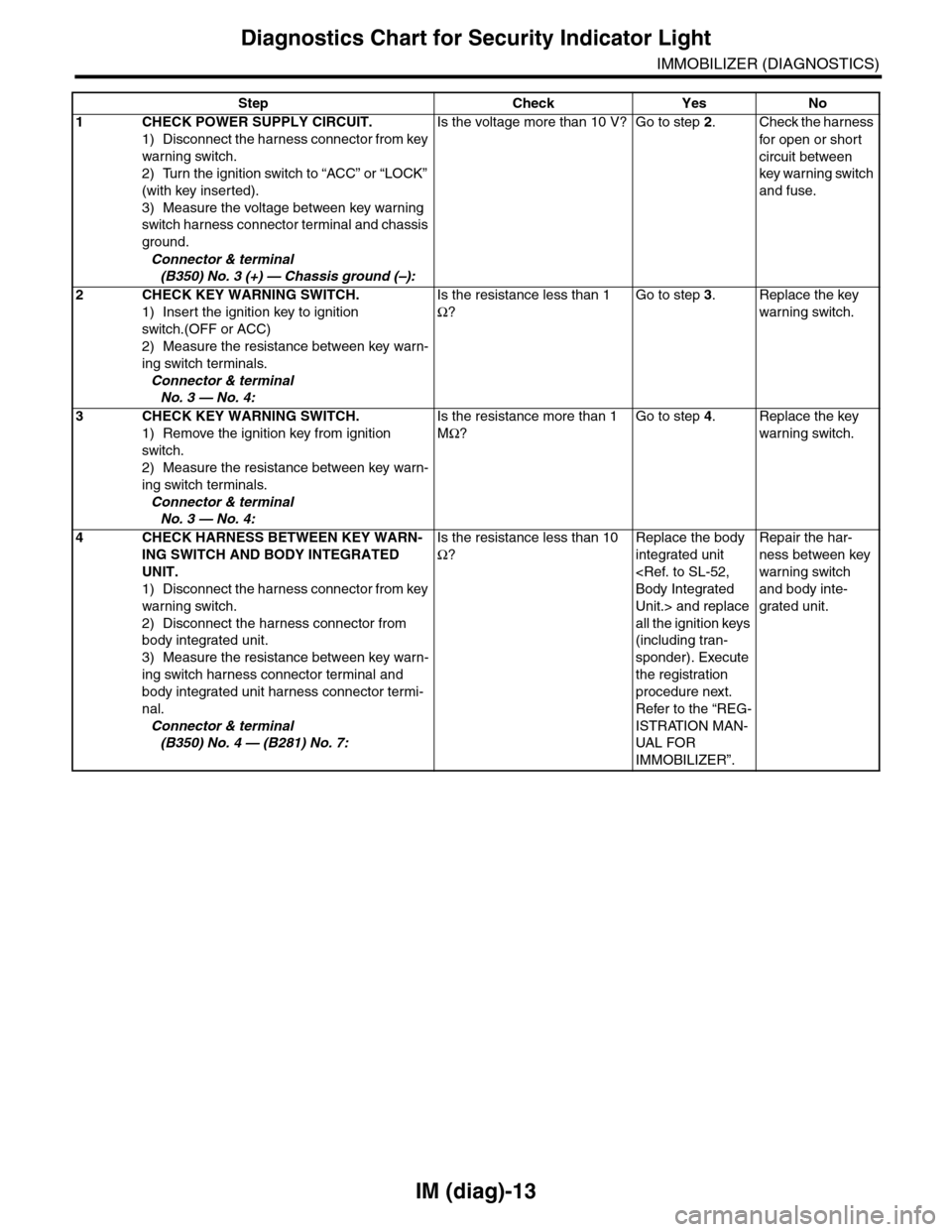
Measure the switch resistance.
NOTE:
•Make sure the battery voltage is applied to the
terminal No. 13(+) and 5(–), when measuring resis-
tance, because the main switch is controlled by mi-
crocomputer.
•Make sure that the window lock switch is mea-
sured in the UNLOCK position.EI-01286
EI-01287
Page 355 of 2453
AC-29
Blower Resistor (Dual A/C Model)
HVAC SYSTEM (HEATER, VENTILATOR AND A/C)
10.Blower Resistor (Dual A/C
Model)
A: REMOVAL
1) Remove the quarter trim.
MOVAL, Rear Quarter Trim.>
2) Disconnect the blower resistor connector.
3) Remove the lock (A) and rotate to the right, and
remove the blower resistor.
B: INSTALLATION
Install in the reverse order of removal.
C: INSPECTION
Measure the blower resistor resistance.
If NG, replace the blower resistor.
Te r m i n a l N o . S t a n d a r d
1 and 3 Approximately 0.42Ω
1 and 2 Approximately 1.42 Ω
4 and 1 Approximately 3.2 Ω
AC-01321
(A)
AC-01322(4)(3)
(1)(2)
Page 429 of 2453

IM (diag)-13
Diagnostics Chart for Security Indicator Light
IMMOBILIZER (DIAGNOSTICS)
Step Check Yes No
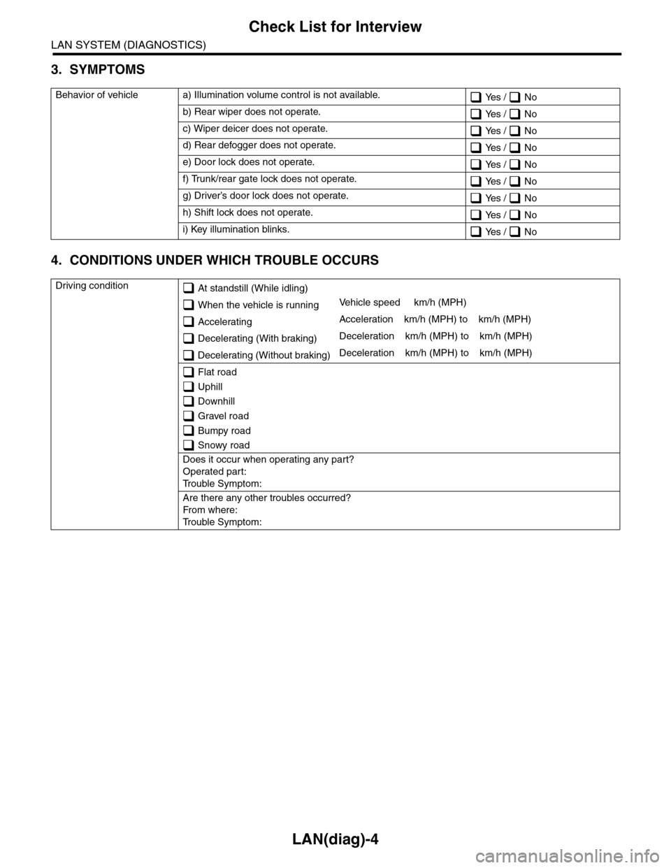
1CHECK POWER SUPPLY CIRCUIT.
1) Disconnect the harness connector from key
warning switch.
2) Turn the ignition switch to “ACC” or “LOCK”
(with key inserted).
3) Measure the voltage between key warning
switch harness connector terminal and chassis
ground.
Connector & terminal
(B350) No. 3 (+) — Chassis ground (–):
Is the voltage more than 10 V? Go to step 2.Check the harness
for open or shor t
circuit between
key warning switch
and fuse.
2 CHECK KEY WARNING SWITCH.
1) Insert the ignition key to ignition
switch.(OFF or ACC)
2) Measure the resistance between key warn-
ing switch terminals.
Connector & terminal
No. 3 — No. 4:
Is the resistance less than 1
Ω?
Go to step 3.Replace the key
warning switch.
3 CHECK KEY WARNING SWITCH.
1) Remove the ignition key from ignition
switch.
2) Measure the resistance between key warn-
ing switch terminals.
Connector & terminal
No. 3 — No. 4:
Is the resistance more than 1
MΩ?
Go to step 4.Replace the key
warning switch.
4CHECK HARNESS BETWEEN KEY WARN-
ING SWITCH AND BODY INTEGRATED
UNIT.
1) Disconnect the harness connector from key
warning switch.
2) Disconnect the harness connector from
body integrated unit.
3) Measure the resistance between key warn-
ing switch harness connector terminal and
body integrated unit harness connector termi-
nal.
Connector & terminal
(B350) No. 4 — (B281) No. 7:
Is the resistance less than 10
Ω?
Replace the body
integrated unit
Body Integrated
Unit.> and replace
all the ignition keys
(including tran-
sponder). Execute
the registration
procedure next.
Refer to the “REG-
ISTRATION MAN-
UAL FO R
IMMOBILIZER”.
Repair the har-
ness between key
warning switch
and body inte-
grated unit.
Page 438 of 2453

IM (diag)-22
Diagnostic Procedure with Diagnostic Trouble Code (DTC)
IMMOBILIZER (DIAGNOSTICS)
E: DTC P1574 KEY COMMUNICATION FAILURE
DTC DETECTING CONDITION:
Failure of body integrated unit to verify key (transponder) ID code
Step Check Yes No
1CHECK BODY INTEGRATED UNIT FUNC-
TION.
Insert the key to ignition switch (LOCK posi-
tion), and measure the changes in voltage
between antenna connectors.
Connector & terminal
(B142) No. 1 (+) — No. 2 (–):
Is the voltage –30 to 30 V?
(Approx. 0.1 second after
inserting the key) Is the voltage
0 V? (Approx. 1 second after
inserting the key)
Go to step 2.Replace the body
integrated unit
Body Integrated
Unit.> and replace
all the ignition keys
(including tran-
sponder). Execute
the registration
procedure next.
Refer to the “REG-
ISTRATION MAN-
UAL FOR
IMMOBILIZER”.
2CHECK IGNITION KEY (TRANSPONDER).
1) Remove the key from ignition switch.
2) Start the engine using other key which is
already registered.
Does the engine start? Replace all the
ignition keys
(including tran-
sponder). Execute
the registration
procedure next.
Refer to the “REG-
ISTRATION MAN-
UAL FO R
IMMOBILIZER”.
Replace the body
integrated unit
Body Integrated
Unit.> and replace
all the ignition keys
(including tran-
sponder). Execute
the registration
procedure next.
Refer to the “REG-
ISTRATION MAN-
UAL FOR
IMMOBILIZER”.
Page 460 of 2453

LAN(diag)-4
Check List for Interview
LAN SYSTEM (DIAGNOSTICS)
3. SYMPTOMS
4. CONDITIONS UNDER WHICH TROUBLE OCCURS
Behavior of vehicle a) Illumination volume control is not available. Yes / No
b) Rear wiper does not operate. Yes / No
c) Wiper deicer does not operate. Yes / No
d) Rear defogger does not operate. Yes / No
e) Door lock does not operate. Yes / No
f) Trunk/rear gate lock does not operate. Yes / No
g) Driver’s door lock does not operate. Yes / No
h) Shift lock does not operate. Yes / No
i) Key illumination blinks. Yes / No
Driving condition At standstill (While idling)
When the vehicle is runningVe h i c l e s p e e d k m / h ( M P H )
AcceleratingAcceleration km/h (MPH) to km/h (MPH)
Decelerating (With braking)Deceleration km/h (MPH) to km/h (MPH)
Decelerating (Without braking)Deceleration km/h (MPH) to km/h (MPH)
Flat road
Uphill
Downhill
Gravel road
Bumpy road
Snowy road
Does it occur when operating any part?
Operated part:
Tr o u b l e S y m p t o m :
Are there any other troubles occurred?
Fr o m wh er e :
Tr o u b l e S y m p t o m :
Page 465 of 2453

LAN(diag)-9
Control Module I/O Signal
LAN SYSTEM (DIAGNOSTICS)
5. Control Module I/O Signal
A: ELECTRICAL SPECIFICATION
DescriptionConnec-
tor No.
Te r m i n a l
No.
Signal (V)
NoteIgnition switch ON
(Engine OFF)
System control power
supplyB281 C2 10 — 13 V Always
Backup power supply B280 B7 10 — 13 V Always
Ignition power supply i84 A1 10 — 13 V Ignition ON
ACC power supply i84 A24 10 — 13 V AC C ON
Ground
i84 A21
0 V AlwaysB281 C9
B281 C8
B280 B22
Key war ning switch B281 C7 10 — 13 V When ignition key inser ted
Stop light switch B281 C23 10 — 13 V When brake pedal depressed
Illumination control switch
(Bright switch)i84 A30 10 — 13 V (at dimmer ON)Cancel the extinction of the clock and
audio illumination
Illumination control switch i84 A30 10 — 13 V (at dimmer ON) Extinct the clock and audio illumination
Illumination volume (Vi1) i84 A10 4.5 — 5.5 V Small light ON
Illumination volume (Vi2) i84 A2 0.5 — 4.5 V —
Illumination volume (Vi3) i84 A25 0 V Ground circuit
Illumination output i84 A5 10 — 13 V Small light ON
Fr o nt fog li g ht in p ut B 28 1 C1 7 1 0 — 1 3 V Fr o nt fo g l i gh t ON
Door switch input Driver’s
seati84 A19 Less than 1 V (10 — 13 V at OFF) Driver’s door open (ON)
Door switch input Passen-
ger’s seati84 A32 Less than 1 V (10 — 13 V at OFF) Passenger’s door open (ON)
Door switch input Rear RH
seati84 A18 Less than 1 V (10 — 13 V at OFF) Rear RH door open (ON)
Door switch input Rear LH
seati84 A31 Less than 1 V (10 — 13 V at OFF) Rear LH door open (ON)
Door switch
Tr u n k / R e a r g a t ei84 A17 Less than 1 V (10 — 13 V at OFF) Trunk/Rear gate open (ON)
Manual switch (LOCK) i84 A15 Less than 1 ΩDoor lock switch ON
CS-00273
71928
61827
51741626152514241312231122
3102921
1820
B281side
72030
619291828
51741627152614132512241123
3102922
1821
B280side
82335
722342162033
51932183117301615291428
41327
312261121025
1924
i84side