Page 1125 of 2453
CO(H6DO)-6
General Description
COOLING
C: CAUTION
•Wear work clothing, including a cap, protective goggles and protective shoes during operation.
•Remove contamination including dirt and corrosion before removal, installation or disassembly.
•Keep the disassembled parts in order and protect them from dust and dirt.
•Before removal, installation or disassembly, be sure to clarify the failure. Avoid unnecessary removal, in-
stallation, disassembly and replacement.
•Be careful not to burn yourself, because each part on the vehicle is hot after running.
•Be sure to tighten fasteners including bolts and nuts to the specified torque.
•Place shop jacks or rigid racks at the specified points.
•Before disconnecting connectors of sensors or units, be sure to disconnect the ground cable from battery.
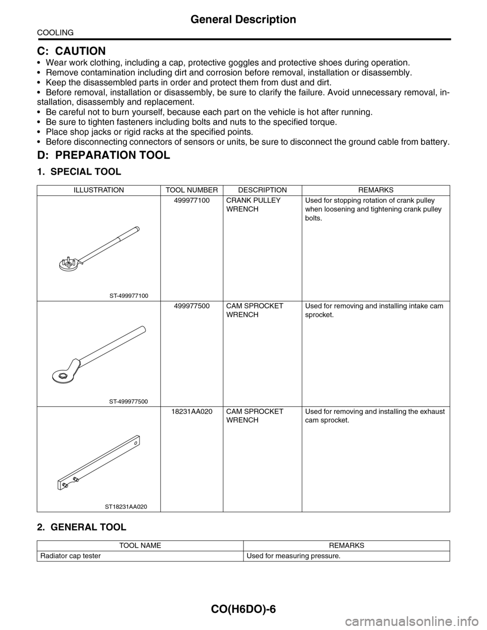
D: PREPARATION TOOL
1. SPECIAL TOOL
2. GENERAL TOOL
ILLUSTRATION TOOL NUMBER DESCRIPTION REMARKS
499977100 CRANK PULLEY
WRENCH
Used for stopping rotation of crank pulley
when loosening and tightening crank pulley
bolts.
499977500 CAM SPROCKET
WRENCH
Used for removing and installing intake cam
sprocket.
18231AA020 CAM SPROCKET
WRENCH
Used for removing and installing the exhaust
cam sprocket.
TOOL NAME REMARKS
Radiator cap tester Used for measuring pressure.
ST-499977100
ST-499977500
ST18231AA020
Page 1134 of 2453
CO(H6DO)-15
Radiator
COOLING
6. Radiator
A: REMOVAL
WARNING:
The radiator is pressurized. Wait until engine
cools down before working on the radiator.
1) Set the vehicle on a lift.
2) Remove the collector cover.
3) Disconnect the ground cable from battery.
4) Lift-up the vehicle.
5) Remove the under cover.
6) Drain engine coolant completely.
COOLANT, REPLACEMENT, Engine Coolant.>
7) Disconnect the radiator hose from radiator.
8) Remove the bolts on the underside of the radia-
tor stay.
9) Lower the vehicle.
10) Remove the air intake duct.
7, REMOVAL, Air Intake Duct.>
11) Remove the front upper cover.
12) Remove the radiator upper brackets.
13) Remove the radiator stay.
(1) Remove the latch.
(2) Remove the radiator hose bracket.
(3) Remove the clip holding the harness.
(4) Remove the bolts on the left side of the radi-
ator stay.
CO-02015
CO-02175
CO-02176
CO-02177
CO-02179
CO-02180
Page 1138 of 2453
CO(H6DO)-19
Radiator
COOLING
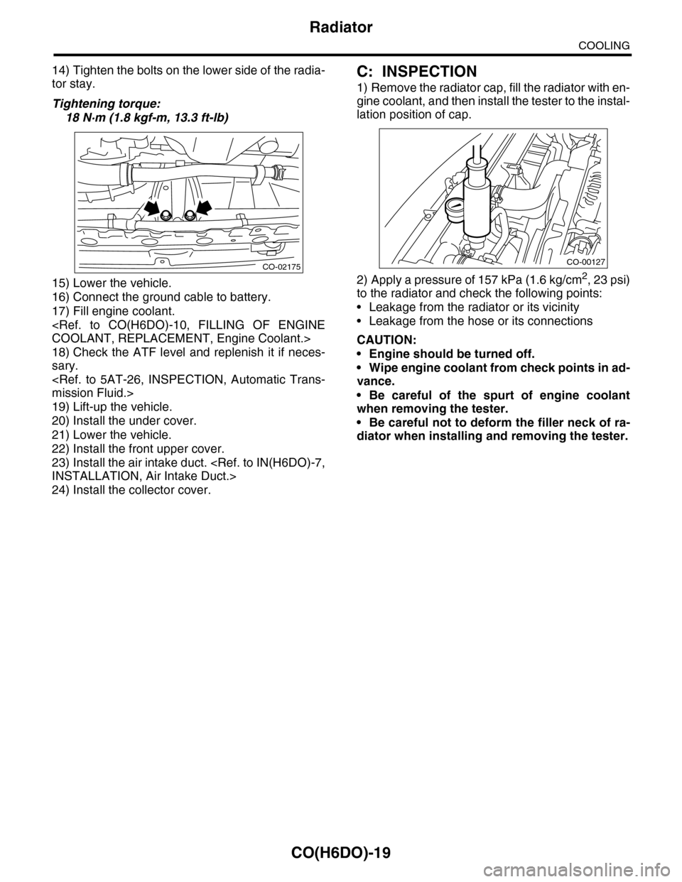
14) Tighten the bolts on the lower side of the radia-
tor stay.
Tightening torque:
18 N·m (1.8 kgf-m, 13.3 ft-lb)
15) Lower the vehicle.
16) Connect the ground cable to battery.
17) Fill engine coolant.
COOLANT, REPLACEMENT, Engine Coolant.>
18) Check the ATF level and replenish it if neces-
sary.
mission Fluid.>
19) Lift-up the vehicle.
20) Install the under cover.
21) Lower the vehicle.
22) Install the front upper cover.
23) Install the air intake duct.
INSTALLATION, Air Intake Duct.>
24) Install the collector cover.
C: INSPECTION
1) Remove the radiator cap, fill the radiator with en-
gine coolant, and then install the tester to the instal-
lation position of cap.
2) Apply a pressure of 157 kPa (1.6 kg/cm2, 23 psi)
to the radiator and check the following points:
•Leakage from the radiator or its vicinity
•Leakage from the hose or its connections
CAUTION:
•Engine should be turned off.
•Wipe engine coolant from check points in ad-
vance.
•Be careful of the spurt of engine coolant
when removing the tester.
•Be careful not to deform the filler neck of ra-
diator when installing and removing the tester.
CO-02175CO-00127
Page 1150 of 2453
EC(H6DO)-2
General Description
EMISSION CONTROL (AUX. EMISSION CONTROL DEVICES)
1. General Description
A: CAUTION
•Wear work clothing, including a cap, protective
goggles and protective shoes during operation.
•Remove contamination including dirt and corro-
sion before removal, installation or disassembly.
•Keep the disassembled parts in order and pro-
tect them from dust and dirt.
•Before removal, installation or disassembly, be
sure to clarify the failure. Avoid unnecessary re-
moval, installation, disassembly and replacement.
•Be careful not to burn yourself, because each
part on the vehicle is hot after running.
•Be sure to tighten fasteners including bolts and
nuts to the specified torque.
•Place shop jacks or rigid racks at the specified
points.
•Before disconnecting connectors of sensors or
units, be sure to disconnect the ground cable from
the battery.
Page 1219 of 2453
EN(H6DO)(diag)-58
Diagnostics for Engine Starting Failure
ENGINE (DIAGNOSTICS)
B: STARTER MOTOR CIRCUIT
CAUTION:
After repair or replacement of faulty parts, perform Clear Memory Mode
OPERATION, Clear Memory Mode.> and Inspection Mode
Inspection Mode.>.
WIRING DIAGRAM:
EN-03735
3220
NO.21
B225
MAIN SBFSBF-6
E
1513
1614
ECM
B136
B72
B14
M
23
B72B225
101112
131415 16
17181920
21222324
25262728
293031 32
333435 36 39 40
3738
129
34
56
78
134562
BATTERY
IGNITIONSWITCH
STARTERRELAYSTARTER MOTOR
B136
16101112131415252430
9871718192028212223293231
123456
2726333435
Page 1222 of 2453
EN(H6DO)(diag)-61
Diagnostics for Engine Starting Failure
ENGINE (DIAGNOSTICS)
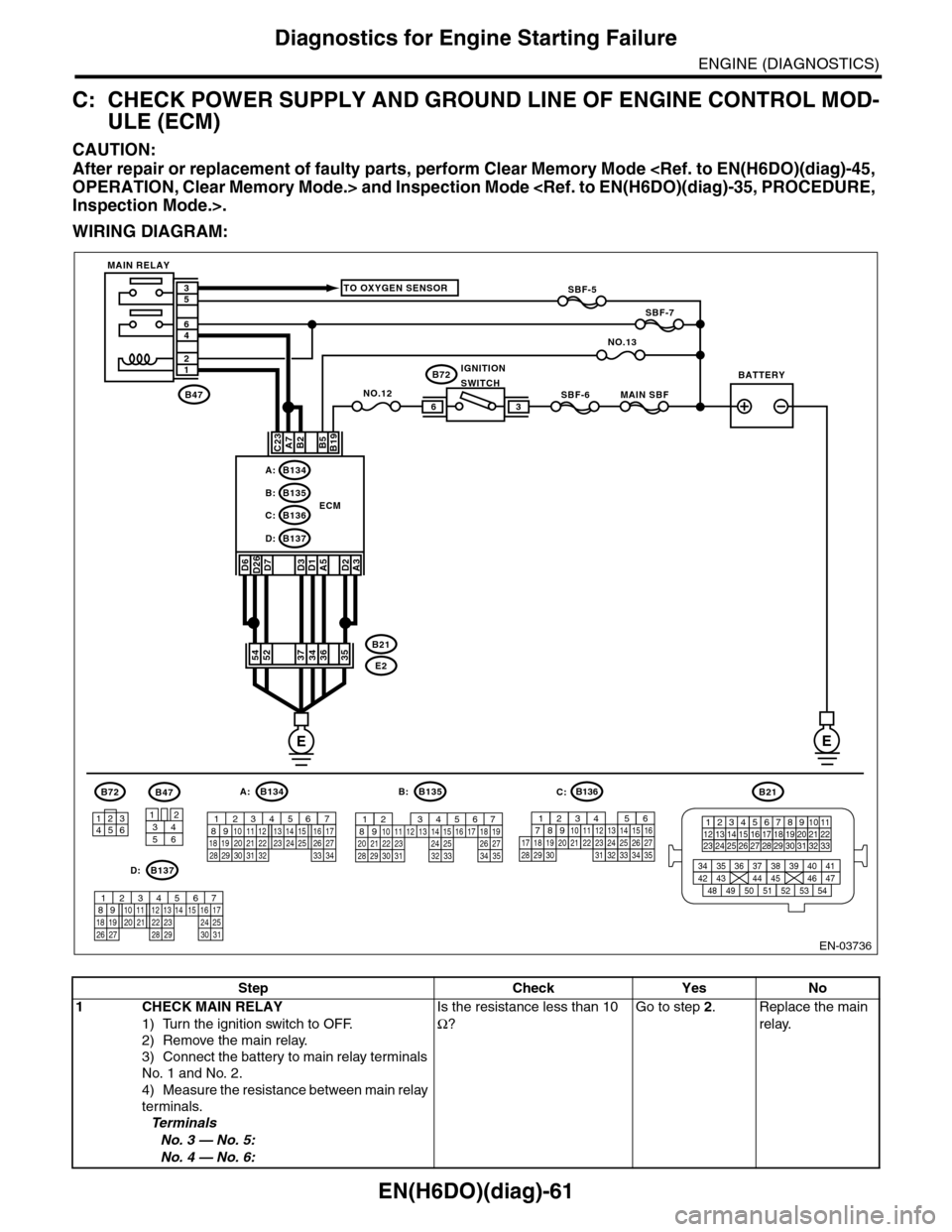
C: CHECK POWER SUPPLY AND GROUND LINE OF ENGINE CONTROL MOD-
ULE (ECM)
CAUTION:
After repair or replacement of faulty parts, perform Clear Memory Mode
OPERATION, Clear Memory Mode.> and Inspection Mode
Inspection Mode.>.
WIRING DIAGRAM:
EN-03736
SBF-6MAIN SBF
SBF-7
B72
B2A7C23
D7D3D1A5
B5B19
NO.12B47
E2
B21
12
46
53
ECM
EE
36
B134A:
D:B137
B135B:
B136C:
A3
52373634
3412
56
B47
TO OXYGEN SENSOR
NO.13
D2
35
B21
123412131415567816171819910 1120212223 24 25 2627 28 29 3031 32 33
3534 37363938 41404342 4445 47464948 51505352 54
B72
134562
B134
56 7821943102422 23 2511 12 13 14 1526 2728
16 1718 19 20 2133 34293230 31
A:B135
567821943102422 23 2511 12 13 14 1526 2728
16 17 18 1920 2129 30 31 32 33 34 35
B:
B137
5678219431022 2311 12 13 14 1524 2526
16 1718 19 20 2127 28 29 30 31
D:
SBF-5
D6D26
54
MAIN RELAY
BATTERYIGNITIONSWITCH
B136
16101112131415252430
9871718192028212223293231
123456
2726333435
C:
Step Check Yes No
1CHECK MAIN RELAY
1) Turn the ignition switch to OFF.
2) Remove the main relay.
3) Connect the battery to main relay terminals
No. 1 and No. 2.
4) Measure the resistance between main relay
terminals.
Te r m i n a l s
No. 3 — No. 5:
No. 4 — No. 6:
Is the resistance less than 10
Ω?
Go to step 2.Replace the main
relay.
Page 1227 of 2453
EN(H6DO)(diag)-66
Diagnostics for Engine Starting Failure
ENGINE (DIAGNOSTICS)
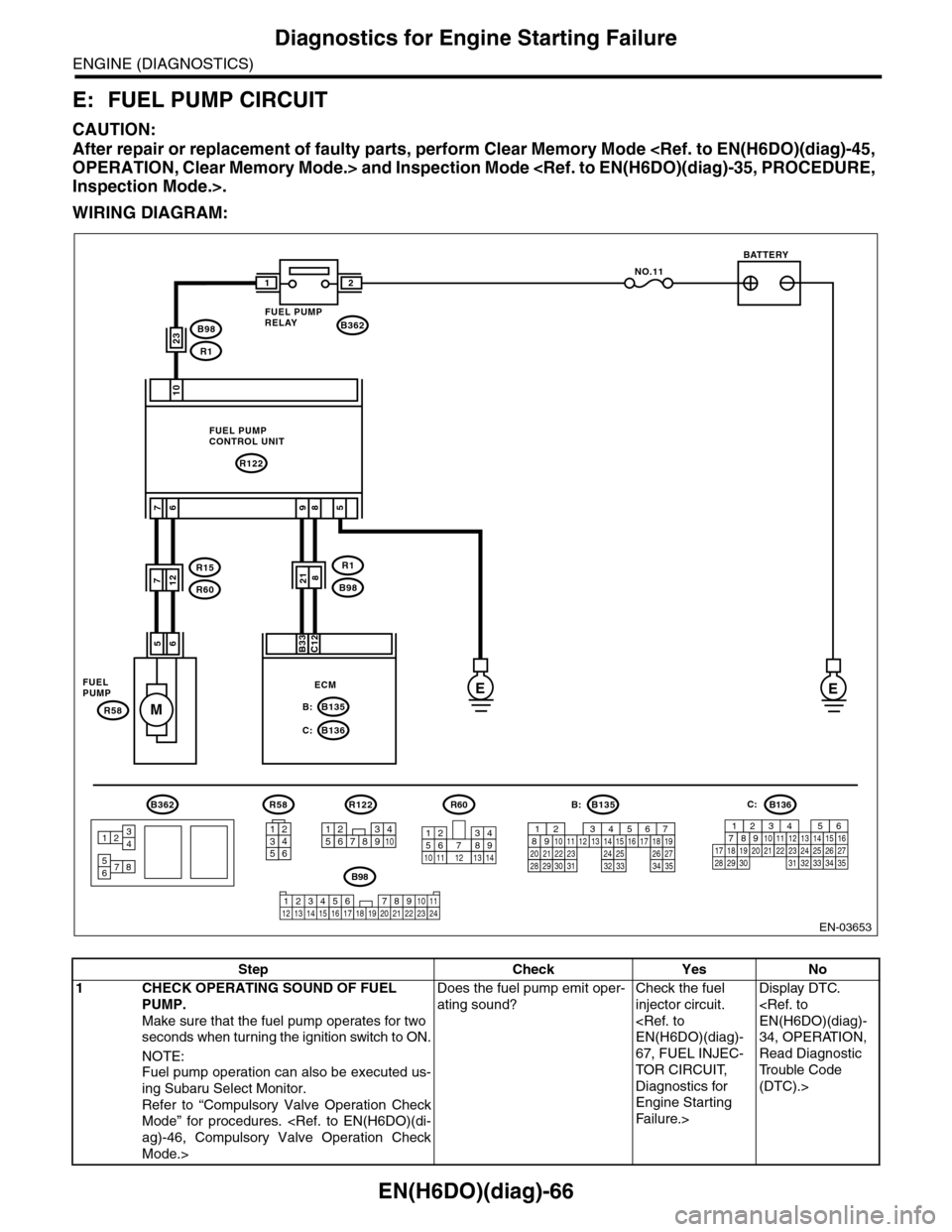
E: FUEL PUMP CIRCUIT
CAUTION:
After repair or replacement of faulty parts, perform Clear Memory Mode
OPERATION, Clear Memory Mode.> and Inspection Mode
Inspection Mode.>.
WIRING DIAGRAM:
EN-03653
EE
M
10
76
56
NO.11
B362
R122
B135B:
B136C:
R58
7
B33C12
21
985
FUEL PUMPCONTROL UNIT
FUELPUMPECM
BATTERY
FUEL PUMPRELAY
B362
5678
3412
R1
B98218
23B98
R1
R15
R60712
R58
2
546
13
B135B:
567821943102422 23 2511 12 13 14 1526 2728
16 17 18 1920 2129 30 31 32 33 34 35
R122
34125891067
B98
123456 78910 1112 13 16 1714 15 18 19 2021222324
R60
12
10115634897131412
B136
16101112131415252430
9871718192028212223293231
123456
2726333435
C:
Step Check Yes No
1CHECK OPERATING SOUND OF FUEL
PUMP.
Make sure that the fuel pump operates for two
seconds when turning the ignition switch to ON.
NOTE:
Fuel pump operation can also be executed us-
ing Subaru Select Monitor.
Refer to “Compulsory Valve Operation Check
Mode” for procedures.
ag)-46, Compulsory Valve Operation Check
Mode.>
Does the fuel pump emit oper-
ating sound?
Check the fuel
injector circuit.
EN(H6DO)(diag)-
67, FUEL INJEC-
TOR CIRCUIT,
Diagnostics for
Engine Starting
Fa il u r e. >
Display DTC.
EN(H6DO)(diag)-
34, OPERATION,
Read Diagnostic
Tr o u b l e C o d e
(DTC).>
Page 1228 of 2453
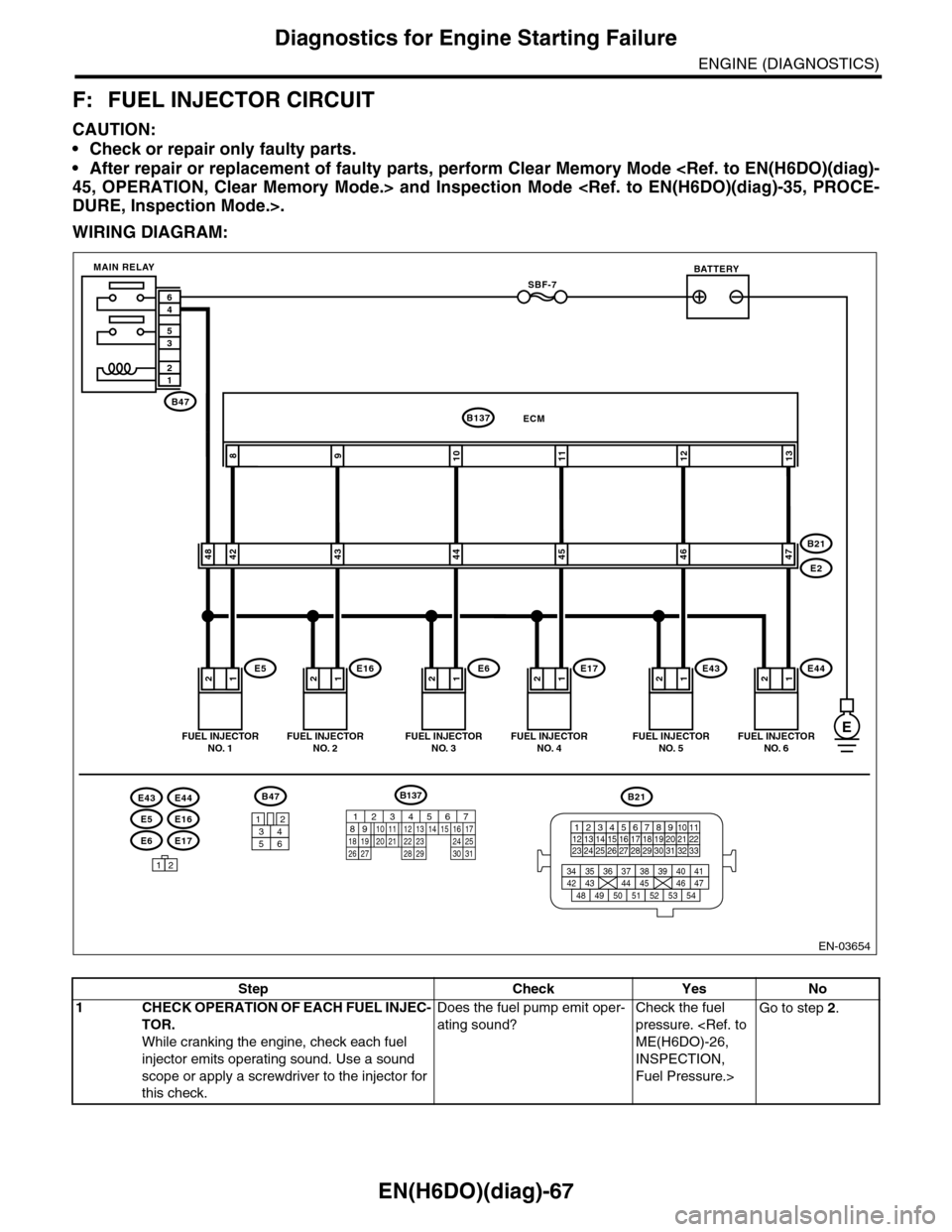
EN(H6DO)(diag)-67
Diagnostics for Engine Starting Failure
ENGINE (DIAGNOSTICS)
F: FUEL INJECTOR CIRCUIT
CAUTION:
•Check or repair only faulty parts.
•After repair or replacement of faulty parts, perform Clear Memory Mode
45, OPERATION, Clear Memory Mode.> and Inspection Mode
DURE, Inspection Mode.>.
WIRING DIAGRAM:
EN-03654
E6E17
E5E16
E43E44
12121212
109811
4248434445
ECMB137
E5E16E6E17
B21
E2
FUEL INJECTORNO. 1FUEL INJECTORNO. 2FUEL INJECTORNO. 3FUEL INJECTORNO. 4
BATTERY
1212
1213
4647
E43E44
FUEL INJECTORNO. 5FUEL INJECTORNO. 6
SBF-7
B47
MAIN RELAY
12
35
46
B47
3412
56
12
B21
123412131415567816171819910 1120212223 24 25 2627 28 29 3031 32 33
3534 37363938 41404342 4445 47464948 51505352 54
E
B137
85610 11 12 13 14 157213416
3019 20 2228 29
91718 2521 23 243126 27
Step Check Yes No
1CHECK OPERATION OF EACH FUEL INJEC-
TOR.
While cranking the engine, check each fuel
injector emits operating sound. Use a sound
scope or apply a screwdriver to the injector for
this check.
Does the fuel pump emit oper-
ating sound?
Check the fuel
pressure.
ME(H6DO)-26,
INSPECTION,
Fuel Pressure.>
Go to step 2.