Page 1424 of 2453

EN(H6DO)(diag)-263
Diagnostic Procedure with Diagnostic Trouble Code (DTC)
ENGINE (DIAGNOSTICS)
BZ:DTC P0340 CAMSHAFT POSITION SENSOR “A” CIRCUIT (BANK 1 OR SIN-
GLE SENSOR)
DTC DETECTING CONDITION:
•Immediately at fault recognition
•GENERAL DESCRIPTION
CIRCUIT (BANK 1 OR SINGLE SENSOR), Diagnostic Trouble Code (DTC) Detecting Criteria.>
TROUBLE SYMPTOM:
•Engine stalls.
•Failure of engine to start
CAUTION:
After repair or replacement of faulty parts, perform Clear Memory Mode
OPERATION, Clear Memory Mode.> and Inspection Mode
Inspection Mode.>.
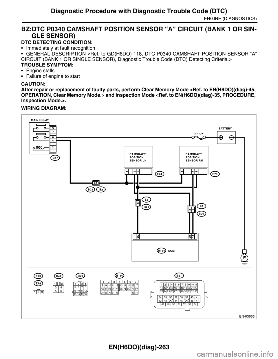
WIRING DIAGRAM:
EN-03665
B47
12
46
35
E
E2
B21
3
22
SBF-7
E74
E1
B20
2E73
B21E2
1
6
3
11
21
ECMB134
48
1
3412
56
B20
E74
B47
123
E73
BATTERY
CAMSHAFTPOSITIONSENSOR RH
CAMSHAFTPOSITIONSENSOR LH
MAIN RELAY
2
21
B21
123412131415567816171819910 1120212223 24 25 2627 28 29 3031 32 33
3534 37363938 41404342 4445 47464948 51505352 54
1234567891011 121314 15 16
B134
85610 11 12 13 14 157213416
3019 20 2228 29
91718252123 24323126 2733 34
Page 1426 of 2453
EN(H6DO)(diag)-265
Diagnostic Procedure with Diagnostic Trouble Code (DTC)
ENGINE (DIAGNOSTICS)
CA:DTC P0345 CAMSHAFT POSITION SENSOR “A” CIRCUIT (BANK 2)
DTC DETECTING CONDITION:
•Immediately at fault recognition
•GENERAL DESCRIPTION
CIRCUIT (BANK 2), Diagnostic Trouble Code (DTC) Detecting Criteria.>
TROUBLE SYMPTOM:
•Engine stalls.
•Failure of engine to start
CAUTION:
After repair or replacement of faulty parts, perform Clear Memory Mode
OPERATION, Clear Memory Mode.> and Inspection Mode
Inspection Mode.>.
WIRING DIAGRAM:
EN-03665
B47
12
46
35
E
E2
B21
3
22
SBF-7
E74
E1
B20
2E73
B21E2
1
6
3
11
21
ECMB134
48
1
3412
56
B20
E74
B47
123
E73
BATTERY
CAMSHAFTPOSITIONSENSOR RH
CAMSHAFTPOSITIONSENSOR LH
MAIN RELAY
2
21
B21
123412131415567816171819910 1120212223 24 25 2627 28 29 3031 32 33
3534 37363938 41404342 4445 47464948 51505352 54
1234567891011 121314 15 16
B134
85610 11 12 13 14 157213416
3019 20 2228 29
91718252123 24323126 2733 34
Page 1433 of 2453
EN(H6DO)(diag)-272
Diagnostic Procedure with Diagnostic Trouble Code (DTC)
ENGINE (DIAGNOSTICS)
CD:DTC P0447 EVAPORATIVE EMISSION CONTROL SYSTEM VENT CONTROL
CIRCUIT OPEN
DTC DETECTING CONDITION:
•Immediately at fault recognition
•GENERAL DESCRIPTION
SYSTEM VENT CONTROL CIRCUIT OPEN, Diagnostic Trouble Code (DTC) Detecting Criteria.>
CAUTION:
After repair or replacement of faulty parts, perform Clear Memory Mode
OPERATION, Clear Memory Mode.> and Inspection Mode
Inspection Mode.>.
WIRING DIAGRAM:
EN-03666
SBF-7
R143R60
R60
R15
R15
R1
R1
B98
B98
B47
ECM
E
17
12
53
64
21
13
9
5
B136
CANISTER
DRAINVA LV E
MAIN RELAYBATTERY
7
B47
3412
56
R143
12
B98
123456 78910 1112 13 16 1714 15 18 19 2021222324
B136
16101112131415252430
9871718192028212223293231
123456
2726333435
R60
12
10115634897131412
Page 1436 of 2453
EN(H6DO)(diag)-275
Diagnostic Procedure with Diagnostic Trouble Code (DTC)
ENGINE (DIAGNOSTICS)
CE:DTC P0448 EVAPORATIVE EMISSION CONTROL SYSTEM VENT CONTROL
CIRCUIT SHORTED
DTC DETECTING CONDITION:
•Immediately at fault recognition
•GENERAL DESCRIPTION
SYSTEM VENT CONTROL CIRCUIT SHORTED, Diagnostic Trouble Code (DTC) Detecting Criteria.>
CAUTION:
After repair or replacement of faulty parts, perform Clear Memory Mode
OPERATION, Clear Memory Mode.> and Inspection Mode
Inspection Mode.>.
WIRING DIAGRAM:
EN-03666
SBF-7
R143R60
R60
R15
R15
R1
R1
B98
B98
B47
ECM
E
17
12
53
64
21
13
9
5
B136
CANISTER
DRAINVA LV E
MAIN RELAYBATTERY
7
B47
3412
56
R143
12
B98
123456 78910 1112 13 16 1714 15 18 19 2021222324
B136
16101112131415252430
9871718192028212223293231
123456
2726333435
R60
12
10115634897131412
Page 1450 of 2453
EN(H6DO)(diag)-289
Diagnostic Procedure with Diagnostic Trouble Code (DTC)
ENGINE (DIAGNOSTICS)
CK:DTC P0458 EVAPORATIVE EMISSION CONTROL SYSTEM PURGE CON-
TROL VALVE CIRCUIT LOW
DTC DETECTING CONDITION:
•Detected when two consecutive driving cycles with fault occur.
•GENERAL DESCRIPTION
SYSTEM PURGE CONTROL VALVE CIRCUIT LOW, Diagnostic Trouble Code (DTC) Detecting Criteria.>
TROUBLE SYMPTOM:
Erroneous idling
CAUTION:
After repair or replacement of faulty parts, perform Clear Memory Mode
OPERATION, Clear Memory Mode.> and Inspection Mode
Inspection Mode.>.
WIRING DIAGRAM:
EN-03668
E4
B47
B47
3412
56
SBF-7
12
46
35
29
B21
E24841
B137ECM
21
E4
12
E
B21
123412131415567816171819910 1120212223 24 25 2627 28 29 3031 32 33
3534 37363938 41404342 4445 47464948 51505352 54
32E76
E77
BATTERY
MAIN RELAY
PURGE CONTROLSOLENOID VALVE
E77
134562
B137
85610 11 12 13 14 157213416
3019 20 2228 29
91718 2521 23 243126 27
Page 1452 of 2453
EN(H6DO)(diag)-291
Diagnostic Procedure with Diagnostic Trouble Code (DTC)
ENGINE (DIAGNOSTICS)
CL:DTC P0459 EVAPORATIVE EMISSION CONTROL SYSTEM PURGE CON-
TROL VALVE CIRCUIT HIGH
DTC DETECTING CONDITION:
•Detected when two consecutive driving cycles with fault occur.
•GENERAL DESCRIPTION
SYSTEM PURGE CONTROL VALVE CIRCUIT HIGH, Diagnostic Trouble Code (DTC) Detecting Criteria.>
TROUBLE SYMPTOM:
Erroneous idling
CAUTION:
After repair or replacement of faulty parts, perform Clear Memory Mode
OPERATION, Clear Memory Mode.> and Inspection Mode
Inspection Mode.>.
WIRING DIAGRAM:
EN-03668
E4
B47
B47
3412
56
SBF-7
12
46
35
29
B21
E24841
B137ECM
21
E4
12
E
B21
123412131415567816171819910 1120212223 24 25 2627 28 29 3031 32 33
3534 37363938 41404342 4445 47464948 51505352 54
32E76
E77
BATTERY
MAIN RELAY
PURGE CONTROLSOLENOID VALVE
E77
134562
B137
85610 11 12 13 14 157213416
3019 20 2228 29
91718 2521 23 243126 27
Page 1461 of 2453

EN(H6DO)(diag)-300
Diagnostic Procedure with Diagnostic Trouble Code (DTC)
ENGINE (DIAGNOSTICS)
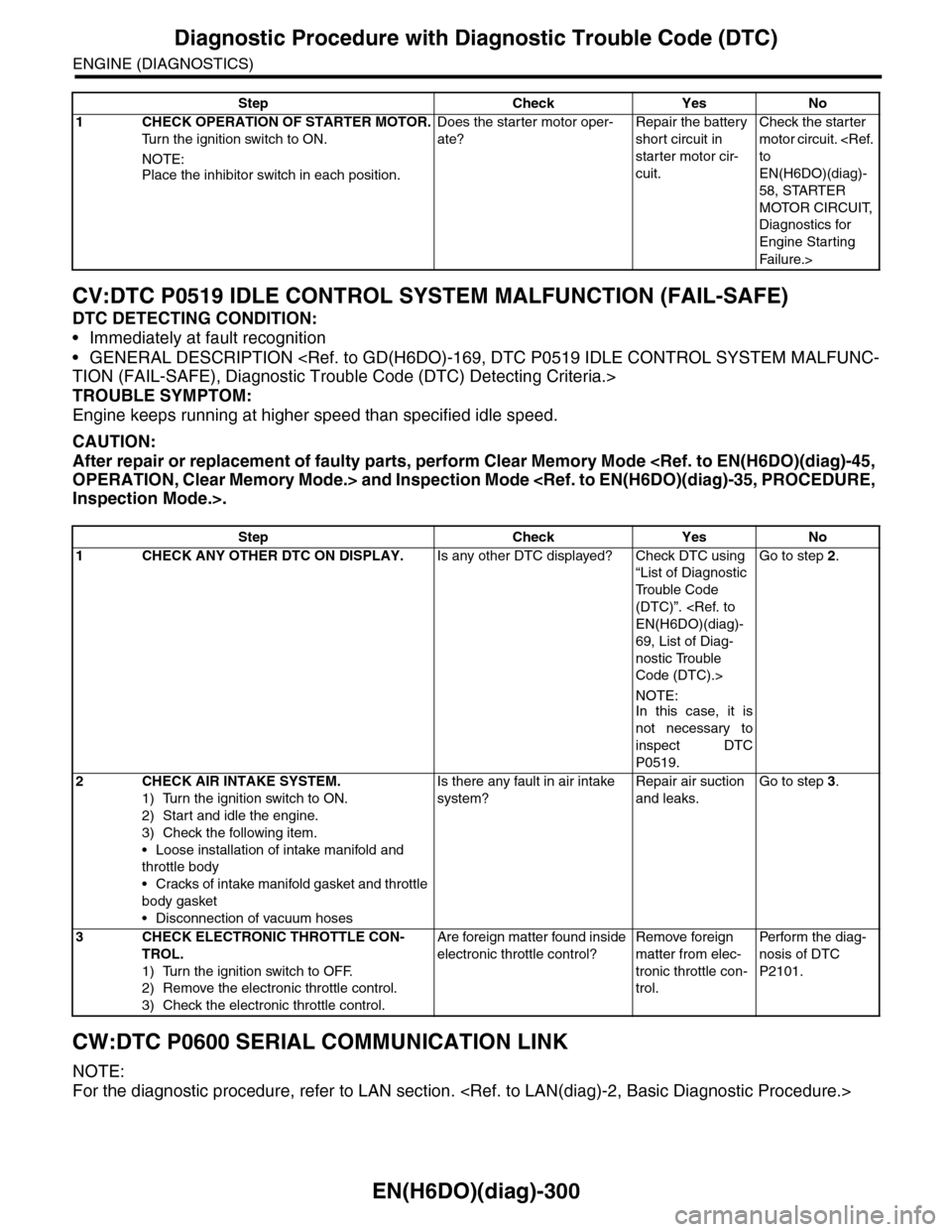
CV:DTC P0519 IDLE CONTROL SYSTEM MALFUNCTION (FAIL-SAFE)
DTC DETECTING CONDITION:
•Immediately at fault recognition
•GENERAL DESCRIPTION
TION (FAIL-SAFE), Diagnostic Trouble Code (DTC) Detecting Criteria.>
TROUBLE SYMPTOM:
Engine keeps running at higher speed than specified idle speed.
CAUTION:
After repair or replacement of faulty parts, perform Clear Memory Mode
OPERATION, Clear Memory Mode.> and Inspection Mode
Inspection Mode.>.
CW:DTC P0600 SERIAL COMMUNICATION LINK
NOTE:
For the diagnostic procedure, refer to LAN section.
Step Check Yes No
1CHECK OPERATION OF STARTER MOTOR.
Tu r n t h e i g n i t i o n s w i t c h t o O N .
NOTE:
Place the inhibitor switch in each position.
Does the starter motor oper-
ate?
Repair the battery
short circuit in
starter motor cir-
cuit.
Check the starter
motor circuit.
to
EN(H6DO)(diag)-
58, STARTER
MOTOR CIRCUIT,
Diagnostics for
Engine Starting
Fai lu r e.>
Step Check Yes No
1CHECK ANY OTHER DTC ON DISPLAY.Is any other DTC displayed? Check DTC using
“List of Diagnostic
Tr o u b l e C o d e
(DTC)”.
EN(H6DO)(diag)-
69, List of Diag-
nostic Trouble
Code (DTC).>
NOTE:In this case, it is
not necessary to
inspect DTC
P0519.
Go to step 2.
2CHECK AIR INTAKE SYSTEM.
1) Turn the ignition switch to ON.
2) Start and idle the engine.
3) Check the following item.
•Loose installation of intake manifold and
throttle body
•Cracks of intake manifold gasket and throttle
body gasket
•Disconnection of vacuum hoses
Is there any fault in air intake
system?
Repair air suction
and leaks.
Go to step 3.
3CHECK ELECTRONIC THROTTLE CON-
TROL.
1) Turn the ignition switch to OFF.
2) Remove the electronic throttle control.
3) Check the electronic throttle control.
Are foreign matter found inside
electronic throttle control?
Remove foreign
matter from elec-
tronic throttle con-
trol.
Per fo r m th e di ag -
nosis of DTC
P2101.
Page 1463 of 2453

EN(H6DO)(diag)-302
Diagnostic Procedure with Diagnostic Trouble Code (DTC)
ENGINE (DIAGNOSTICS)
CZ:DTC P0607 CONTROL MODULE PERFORMANCE
DTC DETECTING CONDITION:
•Immediately at fault recognition
•GENERAL DESCRIPTION
Diagnostic Trouble Code (DTC) Detecting Criteria.>
TROUBLE SYMPTOM:
•Erroneous idling
•Poor driving performance
CAUTION:
After repair or replacement of faulty parts, perform Clear Memory Mode
OPERATION, Clear Memory Mode.> and Inspection Mode
Inspection Mode.>.
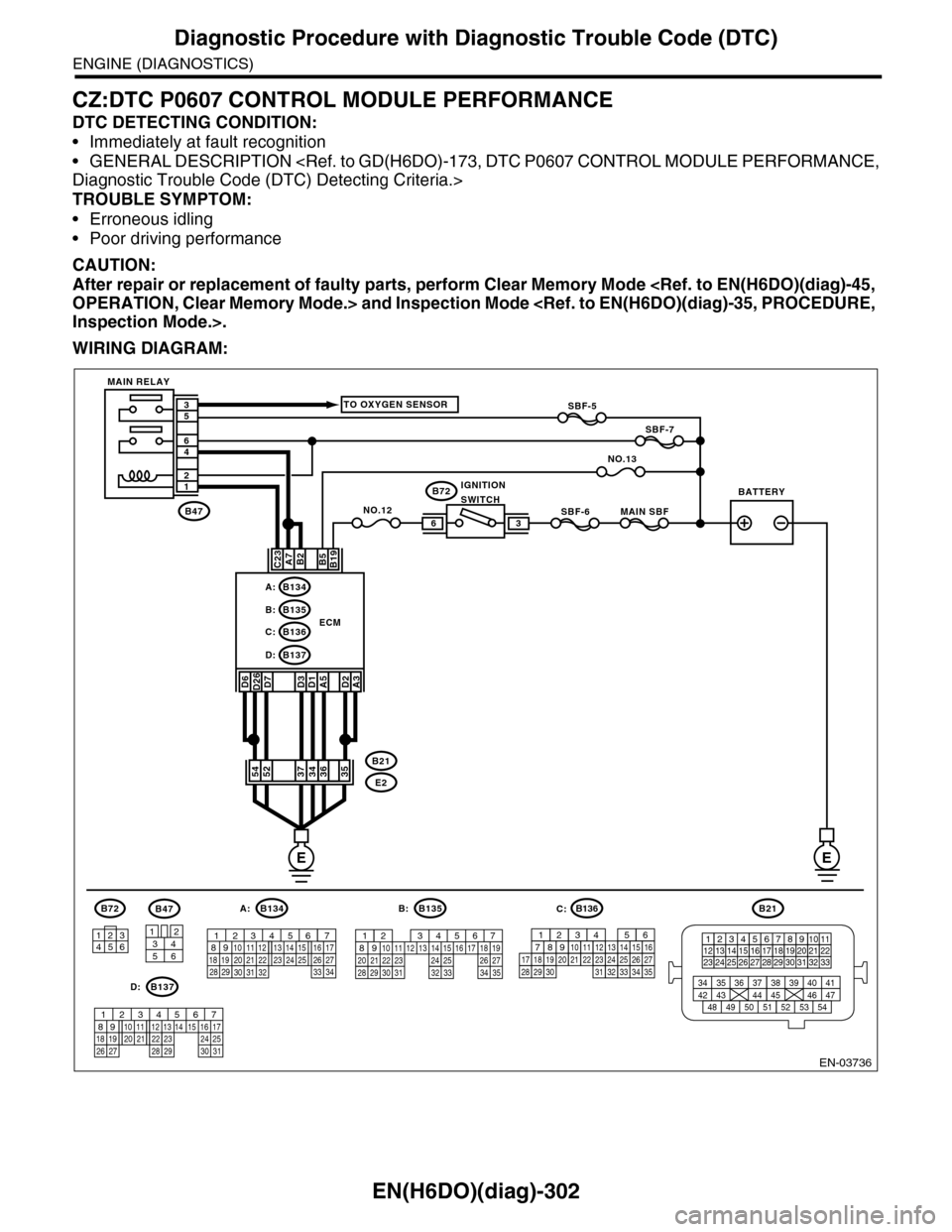
WIRING DIAGRAM:
EN-03736
SBF-6MAIN SBF
SBF-7
B72
B2A7C23
D7D3D1A5
B5B19
NO.12B47
E2
B21
12
46
53
ECM
EE
36
B134A:
D:B137
B135B:
B136C:
A3
52373634
3412
56
B47
TO OXYGEN SENSOR
NO.13
D2
35
B21
123412131415567816171819910 1120212223 24 25 2627 28 29 3031 32 33
3534 37363938 41404342 4445 47464948 51505352 54
B72
134562
B134
56 7821943102422 23 2511 12 13 14 1526 2728
16 1718 19 20 2133 34293230 31
A:B135
567821943102422 23 2511 12 13 14 1526 2728
16 17 18 1920 2129 30 31 32 33 34 35
B:
B137
5678219431022 2311 12 13 14 1524 2526
16 1718 19 20 2127 28 29 30 31
D:
SBF-5
D6D26
54
MAIN RELAY
BATTERYIGNITIONSWITCH
B136
16101112131415252430
9871718192028212223293231
123456
2726333435
C: