Page 1904 of 2453

ME(H6DO)-38
Engine Assembly
MECHANICAL
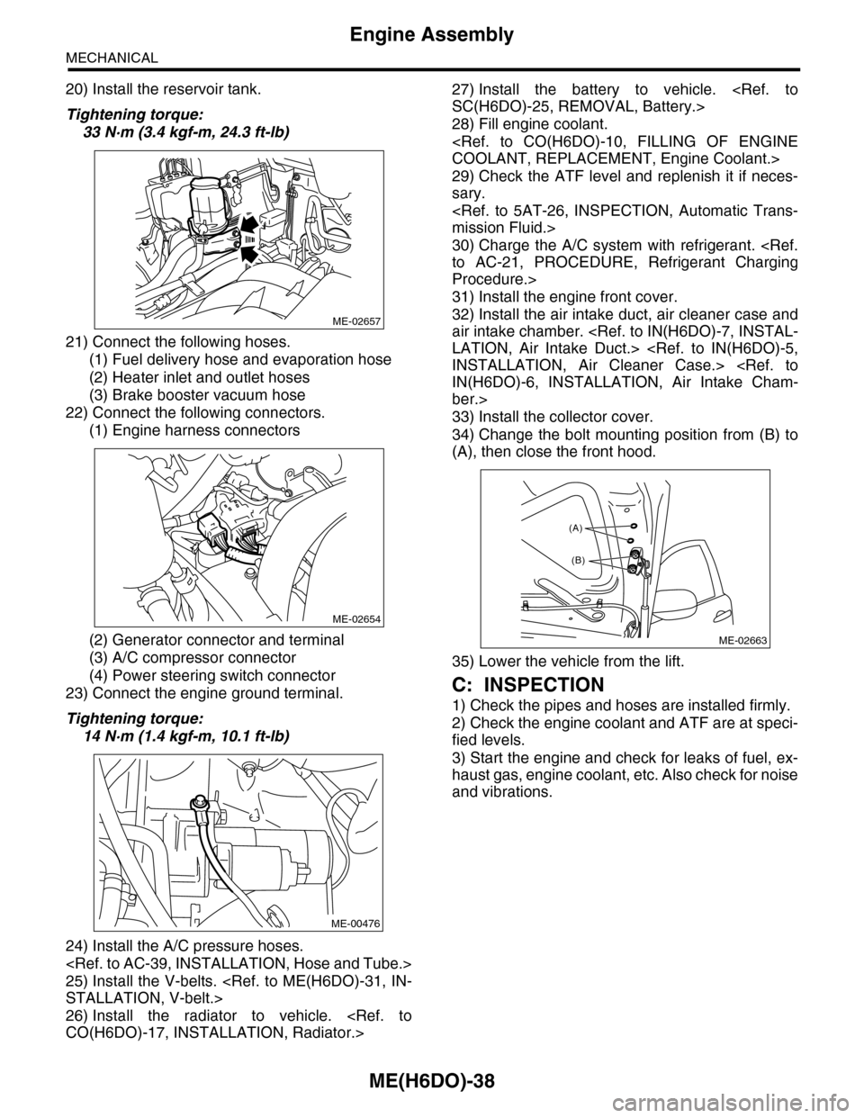
20) Install the reservoir tank.
Tightening torque:
33 N·m (3.4 kgf-m, 24.3 ft-lb)
21) Connect the following hoses.
(1) Fuel delivery hose and evaporation hose
(2) Heater inlet and outlet hoses
(3) Brake booster vacuum hose
22) Connect the following connectors.
(1) Engine harness connectors
(2) Generator connector and terminal
(3) A/C compressor connector
(4) Power steering switch connector
23) Connect the engine ground terminal.
Tightening torque:
14 N·m (1.4 kgf-m, 10.1 ft-lb)
24) Install the A/C pressure hoses.
25) Install the V-belts.
STALLATION, V-belt.>
26) Install the radiator to vehicle.
CO(H6DO)-17, INSTALLATION, Radiator.>
27) Install the battery to vehicle.
SC(H6DO)-25, REMOVAL, Battery.>
28) Fill engine coolant.
COOLANT, REPLACEMENT, Engine Coolant.>
29) Check the ATF level and replenish it if neces-
sary.
mission Fluid.>
30) Charge the A/C system with refrigerant.
to AC-21, PROCEDURE, Refrigerant Charging
Procedure.>
31) Install the engine front cover.
32) Install the air intake duct, air cleaner case and
air intake chamber.
LATION, Air Intake Duct.>
INSTALLATION, Air Cleaner Case.>
IN(H6DO)-6, INSTALLATION, Air Intake Cham-
ber.>
33) Install the collector cover.
34) Change the bolt mounting position from (B) to
(A), then close the front hood.
35) Lower the vehicle from the lift.
C: INSPECTION
1) Check the pipes and hoses are installed firmly.
2) Check the engine coolant and ATF are at speci-
fied levels.
3) Start the engine and check for leaks of fuel, ex-
haust gas, engine coolant, etc. Also check for noise
and vibrations.
ME-02657
ME-02654
ME-00476
ME-02663
(A)
(B)
Page 1957 of 2453

SP(H6DO)-2
General Description
SPEED CONTROL SYSTEMS
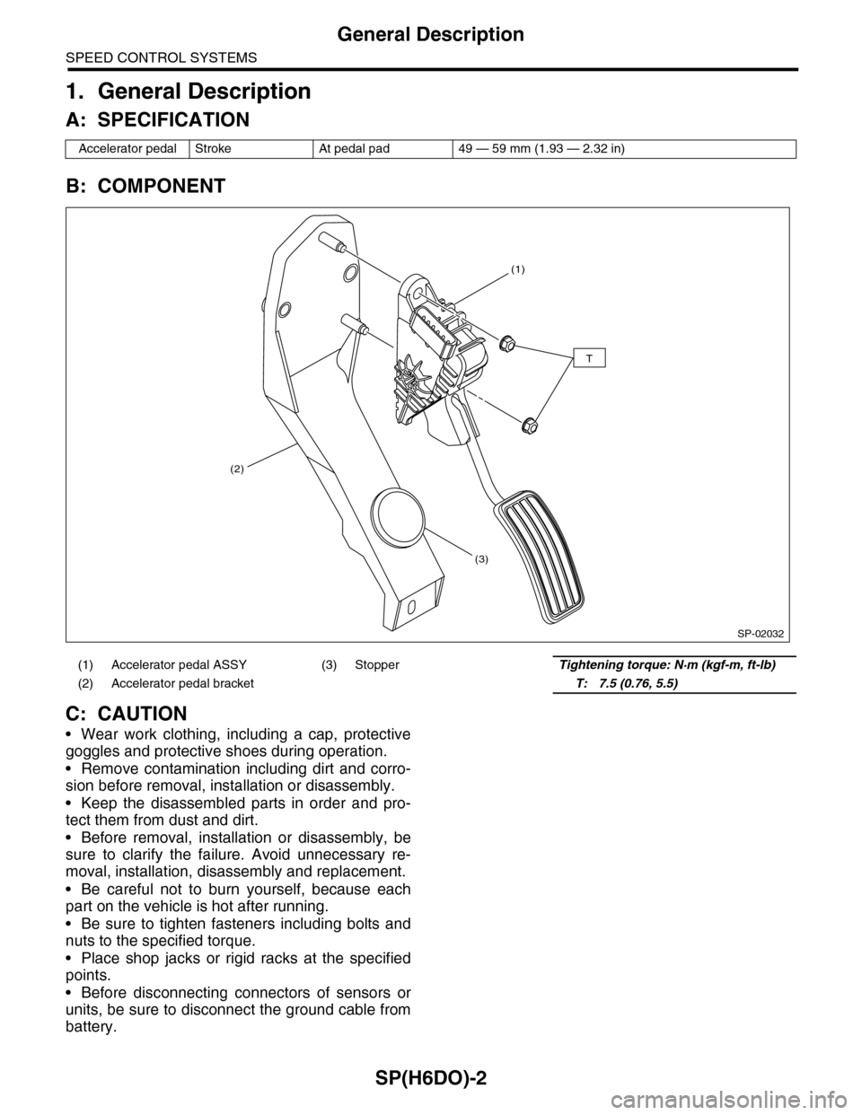
1. General Description
A: SPECIFICATION
B: COMPONENT
C: CAUTION
•Wear work clothing, including a cap, protective
goggles and protective shoes during operation.
•Remove contamination including dirt and corro-
sion before removal, installation or disassembly.
•Keep the disassembled parts in order and pro-
tect them from dust and dirt.
•Before removal, installation or disassembly, be
sure to clarify the failure. Avoid unnecessary re-
moval, installation, disassembly and replacement.
•Be careful not to burn yourself, because each
part on the vehicle is hot after running.
•Be sure to tighten fasteners including bolts and
nuts to the specified torque.
•Place shop jacks or rigid racks at the specified
points.
•Before disconnecting connectors of sensors or
units, be sure to disconnect the ground cable from
battery.
Accelerator pedal Stroke At pedal pad 49 — 59 mm (1.93 — 2.32 in)
(1) Accelerator pedal ASSY (3) StopperTightening torque: N·m (kgf-m, ft-lb)
(2) Accelerator pedal bracket T: 7.5 (0.76, 5.5)
SP-02032
(1)
(2)
(3)
T
Page 1963 of 2453
SC(H6DO)-5
General Description
STARTING/CHARGING SYSTEMS
C: CAUTION
•Wear work clothing, including a cap, protective
goggles and protective shoes during operation.
•Remove contamination including dirt and corro-
sion before removal, installation or disassembly.
•Keep the disassembled parts in order and pro-
tect them from dust and dirt.
•Before removal, installation or disassembly, be
sure to clarify the failure. Avoid unnecessary re-
moval, installation, disassembly and replacement.
•Be careful not to burn yourself, because each
part on the vehicle is hot after running.
•Be sure to tighten fasteners including bolts and
nuts to the specified torque.
•Place shop jacks or rigid racks at the specified
points.
•Before disconnecting connectors of sensors or
units, be sure to disconnect the ground cable from
battery.
Page 1984 of 2453

SC(H6DO)-26
Battery
STARTING/CHARGING SYSTEMS
3. SPECIFIC GRAVITY OF ELECTROLYTE
1) Measure specific gravity of electrolyte using a
hydrometer and a thermometer.
Specific gravity varies with temperature of electro-
lyte so that it must be corrected at 20°C (68°F) us-
ing the following equation:
S20 = St + 0.0007 × (t – 20)
S20: Specific gravity corrected at electrolyte
temperature of 20°C (68°F)
St: Measured specific gravity
t: Measured temperature (°C)
Determine whether or not battery must be
charged, according to corrected specific
gravity.
Standard specific gravity: 1.220 — 1.290
[20°C (68°F)]
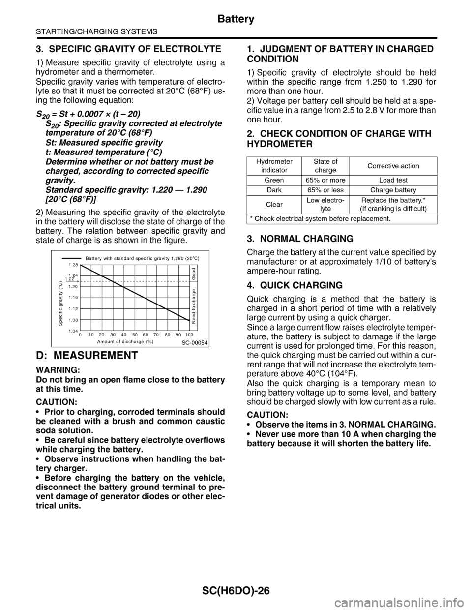
2) Measuring the specific gravity of the electrolyte
in the battery will disclose the state of charge of the
battery. The relation between specific gravity and
state of charge is as shown in the figure.
D: MEASUREMENT
WARNING:
Do not bring an open flame close to the battery
at this time.
CAUTION:
•Prior to charging, corroded terminals should
be cleaned with a brush and common caustic
soda solution.
•Be careful since battery electrolyte overflows
while charging the battery.
•Observe instructions when handling the bat-
tery charger.
•Before charging the battery on the vehicle,
disconnect the battery ground terminal to pre-
vent damage of generator diodes or other elec-
trical units.
1. JUDGMENT OF BATTERY IN CHARGED
CONDITION
1) Specific gravity of electrolyte should be held
within the specific range from 1.250 to 1.290 for
more than one hour.
2) Voltage per battery cell should be held at a spe-
cific value in a range from 2.5 to 2.8 V for more than
one hour.
2. CHECK CONDITION OF CHARGE WITH
HYDROMETER
3. NORMAL CHARGING
Charge the battery at the current value specified by
manufacturer or at approximately 1/10 of battery's
ampere-hour rating.
4. QUICK CHARGING
Quick charging is a method that the battery is
charged in a short period of time with a relatively
large current by using a quick charger.
Since a large current flow raises electrolyte temper-
ature, the battery is subject to damage if the large
current is used for prolonged time. For this reason,
the quick charging must be carried out within a cur-
rent range that will not increase the electrolyte tem-
perature above 40°C (104°F).
Also the quick charging is a temporary mean to
bring battery voltage up to some level, and battery
should be charged slowly with low current as a rule.
CAUTION:
•Observe the items in 3. NORMAL CHARGING.
•Never use more than 10 A when charging the
battery because it will shorten the battery life.
SC-00054
010 20 30 40 50 60 70 80 90 100
1.12
1.20
1.16
1.24
1.28
1.22
1.08
1.04
Amount of discharge (%)
Specific gravity ( C)
Battery with standard specific gravity 1,280 (20 C)
Good
Need to charge
Hydrometer
indicator
State of
chargeCorrective action
Green 65% or more Load test
Dark 65% or less Charge battery
ClearLow electro-
lyte
Replace the battery.*
(If cranking is difficult)
* Check electrical system before replacement.
Page 1992 of 2453
PM-9
Spark Plug
PERIODIC MAINTENANCE SERVICES
5. Spark Plug
A: REPLACEMENT
1) Remove the battery and battery carrier.
2) Remove the air cleaner case.
3) Detach the connector from ignition coil.
4) Remove the ignition coil.
5) Remove the spark plug with a spark plug socket.
6) Tighten the new spark plug lightly with hand, and
then secure with a spark plug socket to the speci-
fied torque.
Recommended spark plug:
NGK: ILFR6B
Tightening torque:
21 N·m (2.1 kgf-m, 15.2 ft-lb)
7) Tighten the ignition coil.
Tightening torque:
16 N·m (1.6 kgf-m, 11.7 ft-lb)
NOTE:
•Be sure to place the gasket between the cylinder
head and spark plug.
•If the torque wrench is not available, tighten the
spark plug until gasket contacts cylinder head; then
tighten further 1/4 to 1/2 turns.
(A) Bracket
(B) Connector
IG-02004(B)
(A)
PM-00112
Page 1995 of 2453
PM-12
Air Cleaner Element
PERIODIC MAINTENANCE SERVICES
8. Air Cleaner Element
A: REPLACEMENT
1) Disconnect the ground cable from battery.
2) Remove the clips (B) on air cleaner case.
3) While pushing the duct toward the back end of
the vehicle, remove the air cleaner element.
4) Install in the reverse order of removal.
NOTE:
Fasten with a clip after inserting the lower tab of
case.
PM-00284
(A)
PM-00285
Page 2056 of 2453

5AT-40
Automatic Transmission Assembly
AUTOMATIC TRANSMISSION
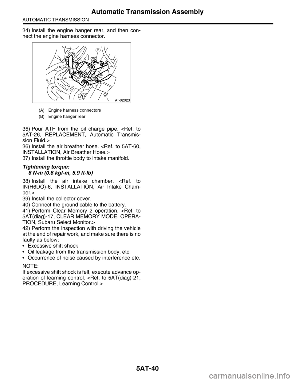
34) Install the engine hanger rear, and then con-
nect the engine harness connector.
35) Pour ATF from the oil charge pipe.
5AT-26, REPLACEMENT, Automatic Transmis-
sion Fluid.>
36) Install the air breather hose.
INSTALLATION, Air Breather Hose.>
37) Install the throttle body to intake manifold.
Tightening torque:
8 N·m (0.8 kgf-m, 5.9 ft-lb)
38) Install the air intake chamber.
IN(H6DO)-6, INSTALLATION, Air Intake Cham-
ber.>
39) Install the collector cover.
40) Connect the ground cable to the battery.
41) Perform Clear Memory 2 operation.
5AT(diag)-17, CLEAR MEMORY MODE, OPERA-
TION, Subaru Select Monitor.>
42) Perform the inspection with driving the vehicle
at the end of repair work, and make sure there is no
faulty as below;
•Excessive shift shock
•Oil leakage from the transmission body, etc.
•Occurrence of noise caused by interference etc.
NOTE:
If excessive shift shock is felt, execute advance op-
eration of learning control.
PROCEDURE, Learning Control.>
(A) Engine harness connectors
(B) Engine hanger rear
(B)
(A)
(A)
AT-02023