2009 SUBARU TRIBECA battery replacement
[x] Cancel search: battery replacementPage 1474 of 2453
EN(H6DO)(diag)-313
Diagnostic Procedure with Diagnostic Trouble Code (DTC)
ENGINE (DIAGNOSTICS)
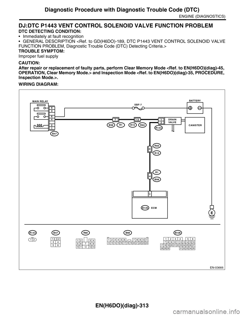
DJ:DTC P1443 VENT CONTROL SOLENOID VALVE FUNCTION PROBLEM
DTC DETECTING CONDITION:
•Immediately at fault recognition
•GENERAL DESCRIPTION
TROUBLE SYMPTOM:
Improper fuel supply
CAUTION:
After repair or replacement of faulty parts, perform Clear Memory Mode
WIRING DIAGRAM:
EN-03666
SBF-7
R143R60
R60
R15
R15
R1
R1
B98
B98
B47
ECM
E
17
12
53
64
21
13
9
5
B136
CANISTER
DRAINVA LV E
MAIN RELAYBATTERY
7
B47
3412
56
R143
12
B98
123456 78910 1112 13 16 1714 15 18 19 2021222324
B136
16101112131415252430
9871718192028212223293231
123456
2726333435
R60
12
10115634897131412
Page 1479 of 2453
EN(H6DO)(diag)-318
Diagnostic Procedure with Diagnostic Trouble Code (DTC)
ENGINE (DIAGNOSTICS)
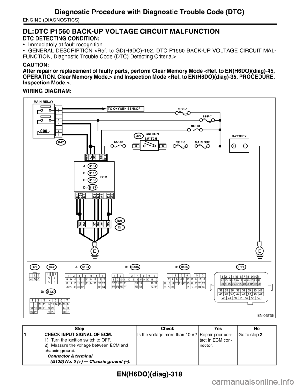
DL:DTC P1560 BACK-UP VOLTAGE CIRCUIT MALFUNCTION
DTC DETECTING CONDITION:
•Immediately at fault recognition
•GENERAL DESCRIPTION
CAUTION:
After repair or replacement of faulty parts, perform Clear Memory Mode
WIRING DIAGRAM:
EN-03736
SBF-6MAIN SBF
SBF-7
B72
B2A7C23
D7D3D1A5
B5B19
NO.12B47
E2
B21
12
46
53
ECM
EE
36
B134A:
D:B137
B135B:
B136C:
A3
52373634
3412
56
B47
TO OXYGEN SENSOR
NO.13
D2
35
B21
123412131415567816171819910 1120212223 24 25 2627 28 29 3031 32 33
3534 37363938 41404342 4445 47464948 51505352 54
B72
134562
B134
56 7821943102422 23 2511 12 13 14 1526 2728
16 1718 19 20 2133 34293230 31
A:B135
567821943102422 23 2511 12 13 14 1526 2728
16 17 18 1920 2129 30 31 32 33 34 35
B:
B137
5678219431022 2311 12 13 14 1524 2526
16 1718 19 20 2127 28 29 30 31
D:
SBF-5
D6D26
54
MAIN RELAY
BATTERYIGNITIONSWITCH
B136
16101112131415252430
9871718192028212223293231
123456
2726333435
C:
Step Check Yes No
1CHECK INPUT SIGNAL OF ECM.
1) Turn the ignition switch to OFF.
2) Measure the voltage between ECM and
chassis ground.
Connector & terminal
(B135) No. 5 (+) — Chassis ground (–):
Is the voltage more than 10 V? Repair poor con-
tact in ECM con-
nector.
Go to step 2.
Page 1557 of 2453
EX(H6DO)-3
General Description
EXHAUST
B: CAUTION
•Wear work clothing, including a cap, protective
goggles and protective shoes during operation.
•Remove contamination including dirt and corro-
sion before removal, installation or disassembly.
•Keep the disassembled parts in order and pro-
tect them from dust and dirt.
•Before removal, installation or disassembly, be
sure to clarify the failure. Avoid unnecessary re-
moval, installation, disassembly and replacement.
•Be careful not to burn yourself, because each
part on the vehicle is hot after running.
•Be sure to tighten fasteners including bolts and
nuts to the specified torque.
•Place shop jacks or rigid racks at the specified
points.
•Before disconnecting connectors of sensors or
units, be sure to disconnect the ground cable from
battery.
(1) Front catalytic converter upper
cover (RH)
(11) Front catalytic converter lower
cover (LH)
(23) Rear exhaust pipe
(24) Cushion rubber
(2) Front catalytic converter lower
cover (RH)
(12) Front exhaust pipe (LH) (25) Self-locking nut
(13) Front catalytic converter (LH) (26) Gasket
(3) Gasket (14) Front oxygen (A/F) sensor (LH)
(4) Front exhaust pipe (RH) (15) Rear oxygen sensor (LH)Tightening torque: N·m (kgf-m, ft-lb)
(5) Front catalytic converter (RH) (16) Muffler (RH)T1: 13 (1.3, 9.4)
(6) Front oxygen (A/F) sensor (RH) (17) Muffler (LH)T2: 18 (1.8, 13.0)
(7) Rear oxygen sensor (RH) (18) Rear catalytic converterT3: 21 (2.1, 15.2)
(8) Gasket (19) BracketT4: 30 (3.1, 22.4)
(9) Gasket (20) GasketT5: 35 (3.6, 26.0)
(10) Front catalytic converter upper
cover (LH)
(21) SpringT6: 48 (4.9, 35.4)
(22) Chamber
Page 1838 of 2453
IG(H6DO)-3
General Description
IGNITION
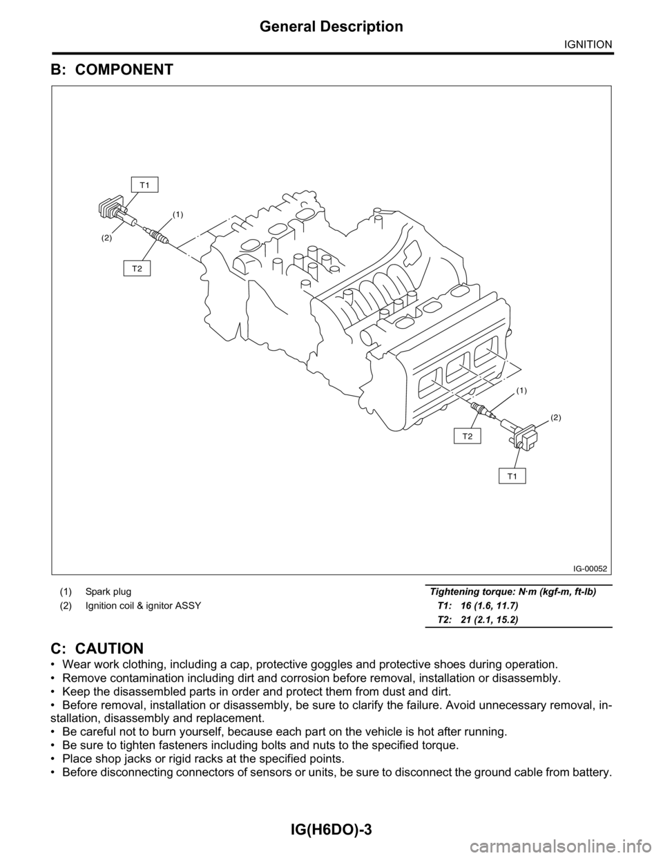
B: COMPONENT
C: CAUTION
•Wear work clothing, including a cap, protective goggles and protective shoes during operation.
•Remove contamination including dirt and corrosion before removal, installation or disassembly.
•Keep the disassembled parts in order and protect them from dust and dirt.
•Before removal, installation or disassembly, be sure to clarify the failure. Avoid unnecessary removal, in-
stallation, disassembly and replacement.
•Be careful not to burn yourself, because each part on the vehicle is hot after running.
•Be sure to tighten fasteners including bolts and nuts to the specified torque.
•Place shop jacks or rigid racks at the specified points.
•Before disconnecting connectors of sensors or units, be sure to disconnect the ground cable from battery.
(1) Spark plug Tightening torque: N·m (kgf-m, ft-lb)
(2) Ignition coil & ignitor ASSY T1: 16 (1.6, 11.7)
T2: 21 (2.1, 15.2)
IG-00052
(1)
(1)
(2)
(2)
T1
T2
T2
T1
Page 1845 of 2453
IN(H6DO)-3
General Description
INTAKE (INDUCTION)
B: CAUTION
•Wear work clothing, including a cap, protective
goggles and protective shoes during operation.
•Remove contamination including dirt and corro-
sion before removal, installation or disassembly.
•Keep the disassembled parts in order and pro-
tect them from dust and dirt.
•Before removal, installation or disassembly, be
sure to clarify the failure. Avoid unnecessary re-
moval, installation, disassembly and replacement.
•Be careful not to burn yourself, because each
part on the vehicle is hot after running.
•Be sure to tighten fasteners including bolts and
nuts to the specified torque.
•Place shop jacks or rigid racks at the specified
points.
•Before disconnecting connectors of sensors or
units, be sure to disconnect the ground cable from
the battery.
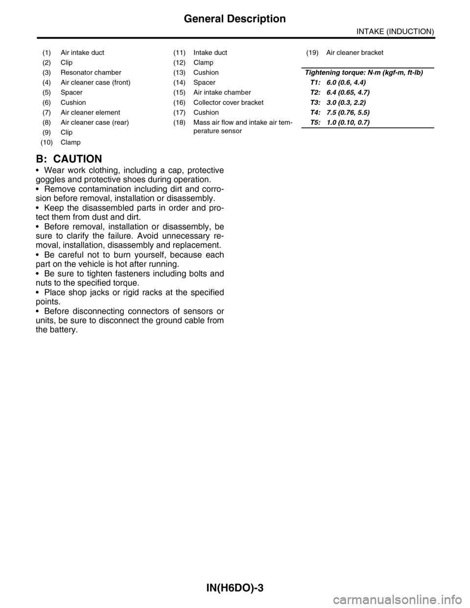
(1) Air intake duct (11) Intake duct (19) Air cleaner bracket
(2) Clip (12) Clamp
(3) Resonator chamber (13) CushionTightening torque: N·m (kgf-m, ft-lb)
(4) Air cleaner case (front) (14) SpacerT1: 6.0 (0.6, 4.4)
(5) Spacer (15) Air intake chamberT2: 6.4 (0.65, 4.7)
(6) Cushion (16) Collector cover bracketT3: 3.0 (0.3, 2.2)
(7) Air cleaner element (17) CushionT4: 7.5 (0.76, 5.5)
(8) Air cleaner case (rear) (18) Mass air flow and intake air tem-
perature sensor
T5: 1.0 (0.10, 0.7)
(9) Clip
(10) Clamp
Page 1853 of 2453
LU(H6DO)-4
General Description
LUBRICATION
C: CAUTION
•Wear work clothing, including a cap, protective goggles and protective shoes during operation.
•Remove contamination including dirt and corrosion before removal, installation or disassembly.
•Keep the disassembled parts in order and protect them from dust and dirt.
•Before removal, installation or disassembly, be sure to clarify the failure. Avoid unnecessary removal, in-
stallation, disassembly and replacement.
•Be careful not to burn yourself, because each part on the vehicle is hot after running.
•Be sure to tighten fasteners including bolts and nuts to the specified torque.
•Place shop jacks or rigid racks at the specified points.
•Before disconnecting connectors of sensors or units, be sure to disconnect the ground cable from battery.
D: PREPARATION TOOL
1. SPECIAL TOOL
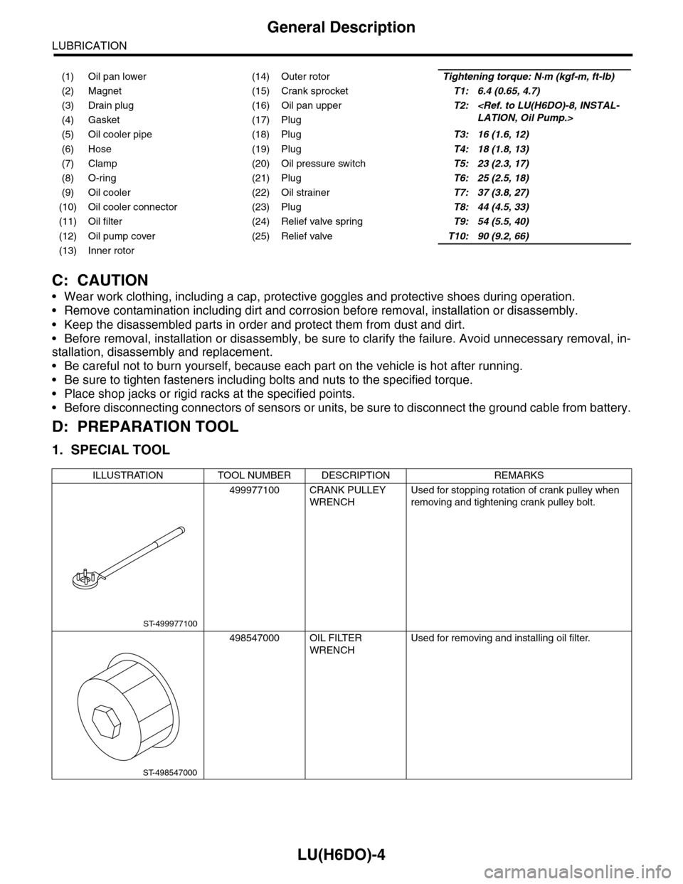
(1) Oil pan lower (14) Outer rotorTightening torque: N·m (kgf-m, ft-lb)
(2) Magnet (15) Crank sprocketT1: 6.4 (0.65, 4.7)
(3) Drain plug (16) Oil pan upperT2:
(5) Oil cooler pipe (18) PlugT3: 16 (1.6, 12)
(6) Hose (19) PlugT4: 18 (1.8, 13)
(7) Clamp (20) Oil pressure switchT5: 23 (2.3, 17)
(8) O-ring (21) PlugT6: 25 (2.5, 18)
(9) Oil cooler (22) Oil strainerT7: 37 (3.8, 27)
(10) Oil cooler connector (23) PlugT8: 44 (4.5, 33)
(11) Oil filter (24) Relief valve springT9: 54 (5.5, 40)
(12) Oil pump cover (25) Relief valveT10: 90 (9.2, 66)
(13) Inner rotor
ILLUSTRATION TOOL NUMBER DESCRIPTION REMARKS
499977100 CRANK PULLEY
WRENCH
Used for stopping rotation of crank pulley when
removing and tightening crank pulley bolt.
498547000 OIL FILTER
WRENCH
Used for removing and installing oil filter.
ST-499977100
ST-498547000
Page 1857 of 2453
LU(H6DO)-8
Oil Pump
LUBRICATION
4. Oil Pump
A: REMOVAL
1) Remove the collector cover.
2) Disconnect the ground cable from battery.
3) Lift-up the vehicle.
4) Remove the under cover.
5) Drain engine coolant.
MENT, Engine Coolant.>
6) Lower the vehicle.
7) Remove the radiator.
8) Remove the V-belts.
9) Remove the front chain cover.
10) Remove the timing chain.
11) Remove the crank sprocket.
12) Remove the oil pump cover.
13) Remove the inner rotor and outer rotor.
B: INSTALLATION
1) Apply a coat of engine oil to the whole area of in-
ner rotor and outer rotor.
2) Set the inner rotor onto opening edge of crank
shaft, and install the inner rotor, and then assemble
the outer rotor.
3) Install the oil pump cover.
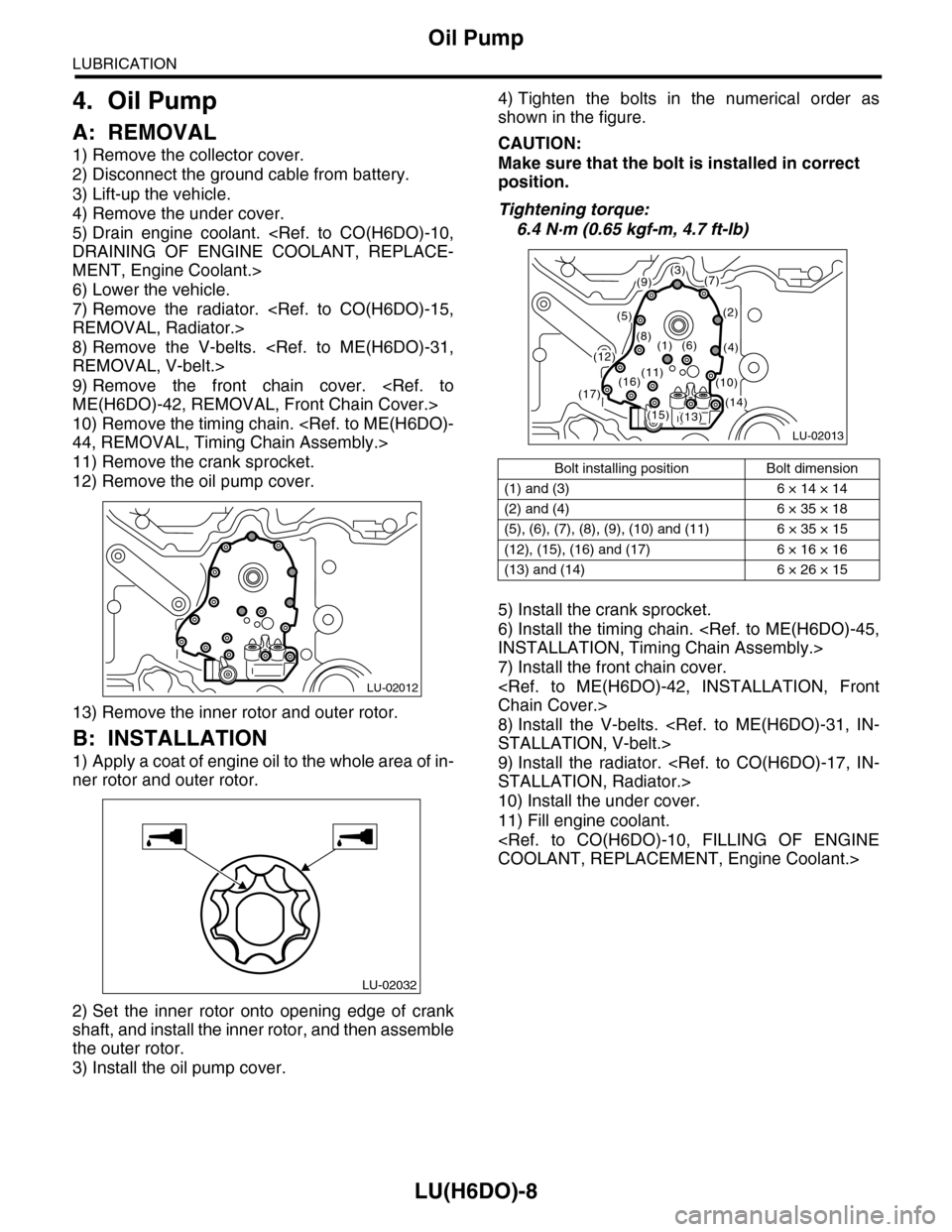
4) Tighten the bolts in the numerical order as
shown in the figure.
CAUTION:
Make sure that the bolt is installed in correct
position.
Tightening torque:
6.4 N·m (0.65 kgf-m, 4.7 ft-lb)
5) Install the crank sprocket.
6) Install the timing chain.
7) Install the front chain cover.
8) Install the V-belts.
9) Install the radiator.
10) Install the under cover.
11) Fill engine coolant.
LU-02012
LU-02032
Bolt installing position Bolt dimension
(1) and (3) 6 × 14 × 14
(2) and (4) 6 × 35 × 18
(5), (6), (7), (8), (9), (10) and (11) 6 × 35 × 15
(12), (15), (16) and (17) 6 × 16 × 16
(13) and (14) 6 × 26 × 15
LU-02013
(3)(7)
(2)
(4)
(9)
(5)
(8)(1)(6)(12)
(13)(14)(15)
(16)(17)
(11)(10)
Page 1880 of 2453
ME(H6DO)-14
General Description
MECHANICAL
8. ENGINE MOUNTING
C: CAUTION
•Wear work clothing, including a cap, protective
goggles and protective shoes during operation.
•Remove contamination including dirt and corro-
sion before removal, installation or disassembly.
•Keep the disassembled parts in order and pro-
tect them from dust and dirt.
•Before removal, installation or disassembly, be
sure to clarify the failure. Avoid unnecessary re-
moval, installation, disassembly and replacement.
•Be careful not to burn yourself, because each
part on the vehicle is hot after running.
•Be sure to tighten fasteners including bolts and
nuts to the specified torque.
•Place shop jacks or rigid racks at the specified
points.
•Before disconnecting connectors of sensors or
units, be sure to disconnect the ground cable from
the battery.
•All parts should be thoroughly cleaned, paying
special attention to engine oil passages, pistons
and bearings.
•Rotating parts and sliding parts such as piston,
bearing and gear should be coated with oil prior to
assembly.
•Be careful not to let oil, grease or coolant contact
the timing belt, clutch disc and flywheel.
•All removed parts, if to be reused, should be re-
installed in the original positions and directions.
•Bolts, nuts and washers should be replaced with
new ones as required.
•Even if necessary inspections have been made
in advance, proceed with assembly work while
making rechecks.
•Remove or install the engine in an area where
chain hoists, lifting devices, etc. are available for
ready use.
•Be sure not to damage coated surfaces of body
panels with tools, or not to stain seats and windows
with coolant or oil. Place a cover over fender, as re-
quired, for protection.
•Prior to starting work, prepare the following:
Service tools, clean cloth, containers to catch cool-
ant and oil, wire ropes, chain hoist, transmission
jacks, etc.
•Lift-up or lower the vehicle when necessary.
Make sure to support the correct positions.
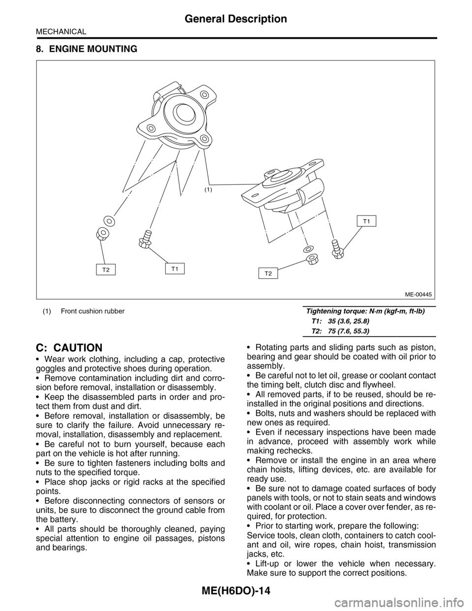
(1) Front cushion rubber Tightening torque: N·m (kgf-m, ft-lb)
T1: 35 (3.6, 25.8)
T2: 75 (7.6, 55.3)
(1)
T2
T1
T1T2
ME-00445