Page 1211 of 2453
EN(H6DO)(diag)-50
Malfunction Indicator Light
ENGINE (DIAGNOSTICS)
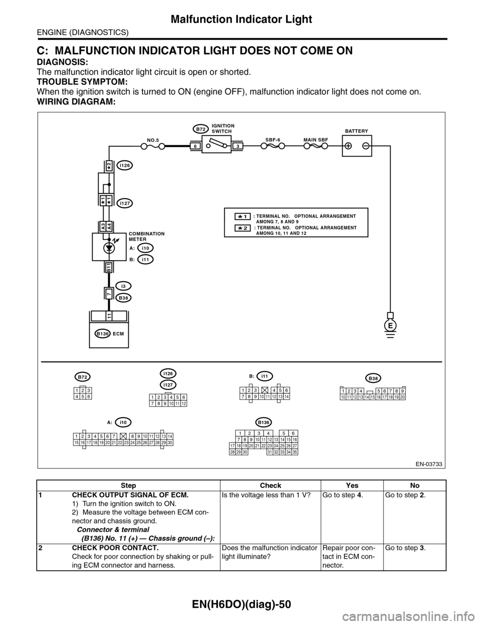
C: MALFUNCTION INDICATOR LIGHT DOES NOT COME ON
DIAGNOSIS:
The malfunction indicator light circuit is open or shorted.
TROUBLE SYMPTOM:
When the ignition switch is turned to ON (engine OFF), malfunction indicator light does not come on.
WIRING DIAGRAM:
EN-03733
3
B72
i3
B38
B136
SBF-66
11
A4
7
MAIN SBFNO.5
B11
E
A3
B72
134562
B38
1234 5678910 11 12 13 14 15 16 17 18 19 20
ECM
COMBINATIONMETER
IGNITIONSWITCHBATTERY
i126
i1271*1*
2*
i10A:
i11B:
i127
i126
123456789101112
1234567891011121314
i11B:
123456789101112131415161718192021222324252627282930
i10A:
2* : TERMINAL NO. OPTIONAL ARRANGEMENT AMONG 10, 11 AND 12
1* : TERMINAL NO. OPTIONAL ARRANGEMENT AMONG 7, 8 AND 9
B136
16101112131415252430
9871718192028212223293231
123456
2726333435
Step Check Yes No
1CHECK OUTPUT SIGNAL OF ECM.
1) Turn the ignition switch to ON.
2) Measure the voltage between ECM con-
nector and chassis ground.
Connector & terminal
(B136) No. 11 (+) — Chassis ground (–):
Is the voltage less than 1 V? Go to step 4.Go to step 2.
2CHECK POOR CONTACT.
Check for poor connection by shaking or pull-
ing ECM connector and harness.
Does the malfunction indicator
light illuminate?
Repair poor con-
tact in ECM con-
nector.
Go to step 3.
Page 1212 of 2453
EN(H6DO)(diag)-51
Malfunction Indicator Light
ENGINE (DIAGNOSTICS)
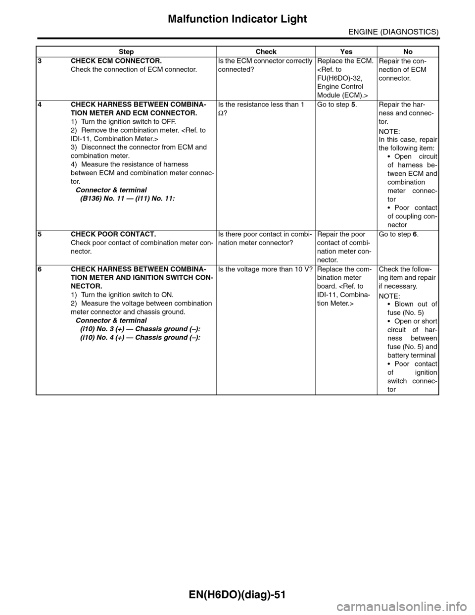
3CHECK ECM CONNECTOR.
Check the connection of ECM connector.
Is the ECM connector correctly
connected?
Replace the ECM.
FU(H6DO)-32,
Engine Control
Module (ECM).>
Repair the con-
nection of ECM
connector.
4CHECK HARNESS BETWEEN COMBINA-
TION METER AND ECM CONNECTOR.
1) Turn the ignition switch to OFF.
2) Remove the combination meter.
IDI-11, Combination Meter.>
3) Disconnect the connector from ECM and
combination meter.
4) Measure the resistance of harness
between ECM and combination meter connec-
tor.
Connector & terminal
(B136) No. 11 — (i11) No. 11:
Is the resistance less than 1
Ω?
Go to step 5.Repair the har-
ness and connec-
tor.
NOTE:In this case, repair
the following item:
•Open circuit
of harness be-
tween ECM and
combination
meter connec-
tor
•Poor contact
of coupling con-
nector
5CHECK POOR CONTACT.
Check poor contact of combination meter con-
nector.
Is there poor contact in combi-
nation meter connector?
Repair the poor
contact of combi-
nation meter con-
nector.
Go to step 6.
6CHECK HARNESS BETWEEN COMBINA-
TION METER AND IGNITION SWITCH CON-
NECTOR.
1) Turn the ignition switch to ON.
2) Measure the voltage between combination
meter connector and chassis ground.
Connector & terminal
(i10) No. 3 (+) — Chassis ground (–):
(i10) No. 4 (+) — Chassis ground (–):
Is the voltage more than 10 V? Replace the com-
bination meter
board.
IDI-11, Combina-
tion Meter.>
Check the follow-
ing item and repair
if necessary.
NOTE:
•Blown out of
fuse (No. 5)
•Open or short
circuit of har-
ness between
fuse (No. 5) and
battery terminal
•Poor contact
of ignition
switch connec-
tor
Step Check Yes No
Page 1213 of 2453
EN(H6DO)(diag)-52
Malfunction Indicator Light
ENGINE (DIAGNOSTICS)
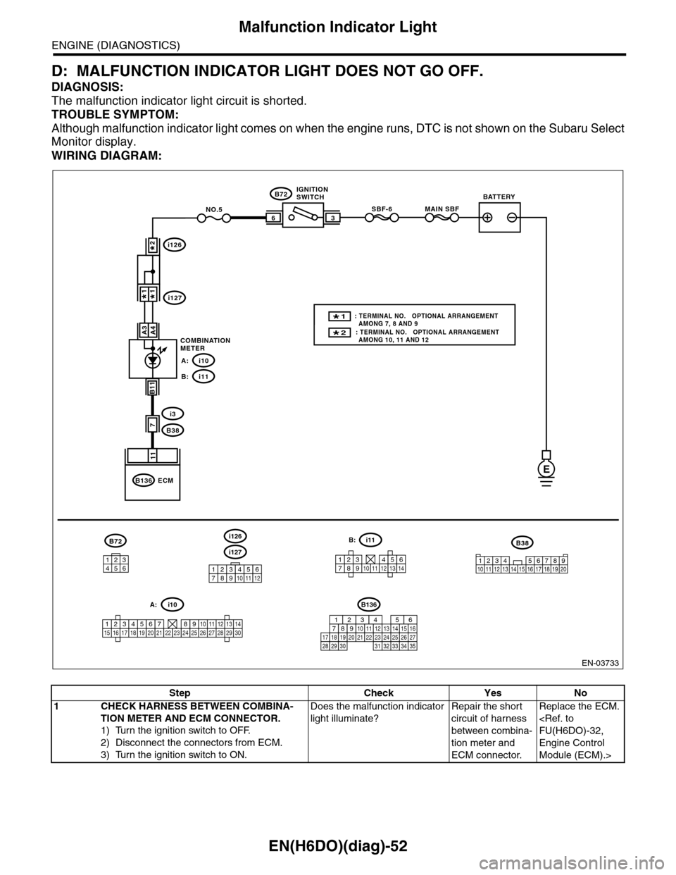
D: MALFUNCTION INDICATOR LIGHT DOES NOT GO OFF.
DIAGNOSIS:
The malfunction indicator light circuit is shorted.
TROUBLE SYMPTOM:
Although malfunction indicator light comes on when the engine runs, DTC is not shown on the Subaru Select
Monitor display.
WIRING DIAGRAM:
EN-03733
3
B72
i3
B38
B136
SBF-66
11
A4
7
MAIN SBFNO.5
B11
E
A3
B72
134562
B38
1234 5678910 11 12 13 14 15 16 17 18 19 20
ECM
COMBINATIONMETER
IGNITIONSWITCHBATTERY
i126
i1271*1*
2*
i10A:
i11B:
i127
i126
123456789101112
1234567891011121314
i11B:
123456789101112131415161718192021222324252627282930
i10A:
2* : TERMINAL NO. OPTIONAL ARRANGEMENT AMONG 10, 11 AND 12
1* : TERMINAL NO. OPTIONAL ARRANGEMENT AMONG 7, 8 AND 9
B136
16101112131415252430
9871718192028212223293231
123456
2726333435
Step Check Yes No
1CHECK HARNESS BETWEEN COMBINA-
TION METER AND ECM CONNECTOR.
1) Turn the ignition switch to OFF.
2) Disconnect the connectors from ECM.
3) Turn the ignition switch to ON.
Does the malfunction indicator
light illuminate?
Repair the short
circuit of harness
between combina-
tion meter and
ECM connector.
Replace the ECM.
FU(H6DO)-32,
Engine Control
Module (ECM).>
Page 1215 of 2453
EN(H6DO)(diag)-54
Malfunction Indicator Light
ENGINE (DIAGNOSTICS)
Step Check Yes No
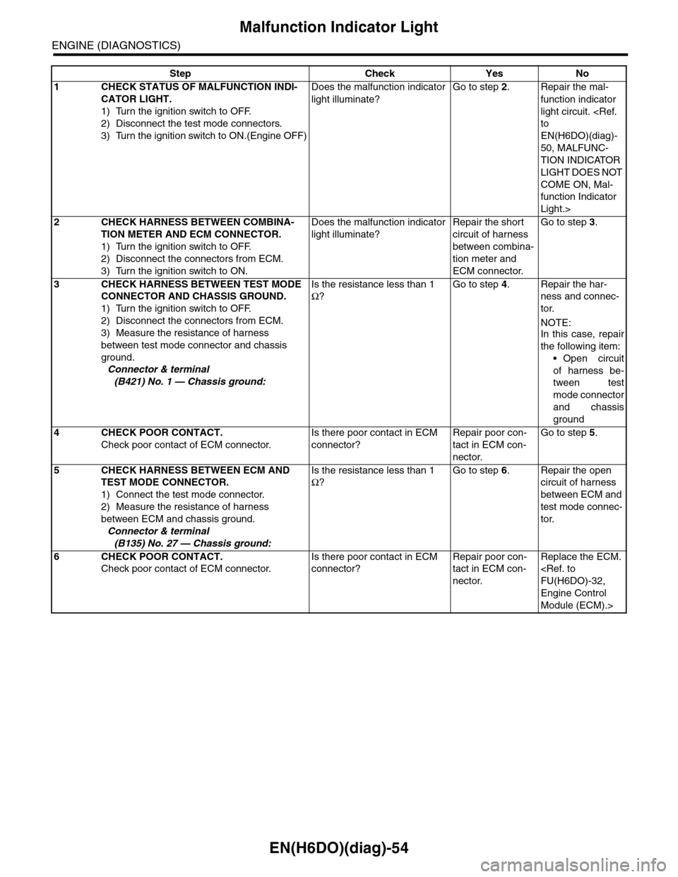
1CHECK STATUS OF MALFUNCTION INDI-
CATOR LIGHT.
1) Turn the ignition switch to OFF.
2) Disconnect the test mode connectors.
3) Turn the ignition switch to ON.(Engine OFF)
Does the malfunction indicator
light illuminate?
Go to step 2.Repair the mal-
function indicator
light circuit.
to
EN(H6DO)(diag)-
50, MALFUNC-
TION INDICATOR
LIGHT DOES NOT
COME ON, Mal-
function Indicator
Light.>
2CHECK HARNESS BETWEEN COMBINA-
TION METER AND ECM CONNECTOR.
1) Turn the ignition switch to OFF.
2) Disconnect the connectors from ECM.
3) Turn the ignition switch to ON.
Does the malfunction indicator
light illuminate?
Repair the short
circuit of harness
between combina-
tion meter and
ECM connector.
Go to step 3.
3CHECK HARNESS BETWEEN TEST MODE
CONNECTOR AND CHASSIS GROUND.
1) Turn the ignition switch to OFF.
2) Disconnect the connectors from ECM.
3) Measure the resistance of harness
between test mode connector and chassis
ground.
Connector & terminal
(B421) No. 1 — Chassis ground:
Is the resistance less than 1
Ω?
Go to step 4.Repair the har-
ness and connec-
tor.
NOTE:
In this case, repair
the following item:
•Open circuit
of harness be-
tween test
mode connector
and chassis
ground
4CHECK POOR CONTACT.
Check poor contact of ECM connector.
Is there poor contact in ECM
connector?
Repair poor con-
tact in ECM con-
nector.
Go to step 5.
5CHECK HARNESS BETWEEN ECM AND
TEST MODE CONNECTOR.
1) Connect the test mode connector.
2) Measure the resistance of harness
between ECM and chassis ground.
Connector & terminal
(B135) No. 27 — Chassis ground:
Is the resistance less than 1
Ω?
Go to step 6.Repair the open
circuit of harness
between ECM and
test mode connec-
tor.
6CHECK POOR CONTACT.
Check poor contact of ECM connector.
Is there poor contact in ECM
connector?
Repair poor con-
tact in ECM con-
nector.
Replace the ECM.
FU(H6DO)-32,
Engine Control
Module (ECM).>
Page 1217 of 2453
EN(H6DO)(diag)-56
Malfunction Indicator Light
ENGINE (DIAGNOSTICS)
Step Check Yes No
1CHECK TEST MODE CONNECTOR.
1) Disconnect the test mode connectors.
2) Turn the ignition switch to ON.
Does the malfunction indicator
light blink?
Go to step 2.System is normal.
NOTE:Malfunction indica-
tor light blinks
when test mode
connector is con-
nected.
2CHECK HARNESS BETWEEN ECM CON-
NECTOR AND CHASSIS GROUND TERMI-
NAL.
1) Turn the ignition switch to OFF.
2) Disconnect the connectors from ECM.
3) Measure the resistance of harness
between ECM connector and chassis ground.
Connector & terminal
(B135) No. 27 — Chassis ground:
Is the resistance less than 5
Ω?
Repair the short
circuit of harness
between ECM and
test mode connec-
tor.
Replace the ECM.
FU(H6DO)-32,
Engine Control
Module (ECM).>
Page 1218 of 2453
EN(H6DO)(diag)-57
Diagnostics for Engine Starting Failure
ENGINE (DIAGNOSTICS)
16.Diagnostics for Engine Starting Failure
A: PROCEDURE
1. Check for fuel amount.
↓
2. Inspection of starter motor circuit.
Fai l ur e. >
↓
3. Inspection of ECM power supply and ground line.
LINE OF ENGINE CONTROL MODULE (ECM), Diagnostics for Engine Starting Failure.>
↓
4. Inspection of ignition control system.
Starting Failure.>
↓
5. Inspection of fuel pump circuit
↓
6. Inspection of fuel injector circuit
ure.>
Page 1220 of 2453
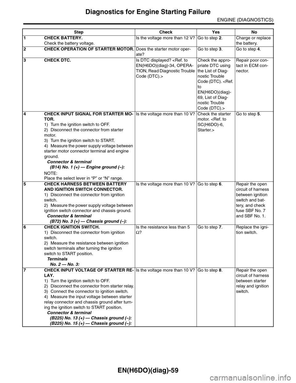
EN(H6DO)(diag)-59
Diagnostics for Engine Starting Failure
ENGINE (DIAGNOSTICS)
Step Check Yes No
1CHECK BATTERY.
Check the battery voltage.
Is the voltage more than 12 V? Go to step 2.Charge or replace
the battery.
2CHECK OPERATION OF STARTER MOTOR.Does the starter motor oper-
ate?
Go to step 3.Go to step 4.
3CHECK DTC.Is DTC displayed?
EN(H6DO)(diag)-34, OPERA-
TION, Read Diagnostic Trouble
Code (DTC).>
Check the appro-
priate DTC using
the List of Diag-
nostic Trouble
Code (DTC).
to
EN(H6DO)(diag)-
69, List of Diag-
nostic Trouble
Code (DTC).>
Repair poor con-
tact in ECM con-
nector.
4CHECK INPUT SIGNAL FOR STARTER MO-
TOR.
1) Turn the ignition switch to OFF.
2) Disconnect the connector from starter
motor.
3) Turn the ignition switch to START.
4) Measure the power supply voltage between
starter motor connector terminal and engine
ground.
Connector & terminal
(B14) No. 1 (+) — Engine ground (–):
NOTE:Place the select lever in “P” or “N” range.
Is the voltage more than 10 V? Check the starter
motor.
SC(H6DO)-6,
Starter.>
Go to step 5.
5CHECK HARNESS BETWEEN BATTERY
AND IGNITION SWITCH CONNECTOR.
1) Disconnect the connector from ignition
switch.
2) Measure the power supply voltage between
ignition switch connector and chassis ground.
Connector & terminal
(B72) No. 3 (+) — Chassis ground (–):
Is the voltage more than 10 V? Go to step 6.Repair the open
circuit of harness
between ignition
switch and bat-
tery, and check
fuse SBF No. 7
and SBF No. 1.
6CHECK IGNITION SWITCH.
1) Disconnect the connector from ignition
switch.
2) Measure the resistance between ignition
switch terminals after turning the ignition
switch to START position.
Te r m i n a l s
No. 2 — No. 3:
Is the resistance less than 5
Ω?
Go to step 7.Replace the igni-
tion switch.
7CHECK INPUT VOLTAGE OF STARTER RE-
LAY.
1) Turn the ignition switch to OFF.
2) Disconnect the connector from starter relay.
3) Connect the connector to ignition switch.
4) Measure the input voltage between starter
relay connector and chassis ground after turn-
ing the ignition switch to START position.
Connector & terminal
(B225) No. 13 (+) — Chassis ground (–):
(B225) No. 15 (+) — Chassis ground (–):
Is the voltage more than 10 V? Go to step 8.Repair the open
circuit of harness
between starter
relay and ignition
switch.
Page 1221 of 2453
EN(H6DO)(diag)-60
Diagnostics for Engine Starting Failure
ENGINE (DIAGNOSTICS)
8CHECK STARTER RELAY.
1) Connect the battery to starter relay termi-
nals No. 15 and No. 16.
2) Measure the resistance between starter
relay terminals.
Te r m i n a l s
No. 13 — No. 14:
Is the resistance less than 1
Ω?
Go to step 9.Replace the
starter relay.
9CHECK INPUT VOLTAGE FROM ECM.
1) Turn the ignition switch to OFF.
2) Connect the connector to starter relay.
3) Disconnect the connectors from ECM.
4) Measure the voltage between ECM and
chassis ground.
Connector & terminal
(B136) No. 32 (+) — Chassis ground (–):
(B136) No. 20 (+) — Chassis ground (–):
Is the voltage more than 10 V? Replace the ECM.
FU(H6DO)-32,
Engine Control
Module (ECM).>
Repair the open or
ground short cir-
cuit of harness
between ECM and
starter relay.
Step Check Yes No