2009 SUBARU TRIBECA check engine
[x] Cancel search: check enginePage 1023 of 2453
VDC(diag)-31
Warning Light Illumination Pattern
VEHICLE DYNAMICS CONTROL (VDC) (DIAGNOSTICS)
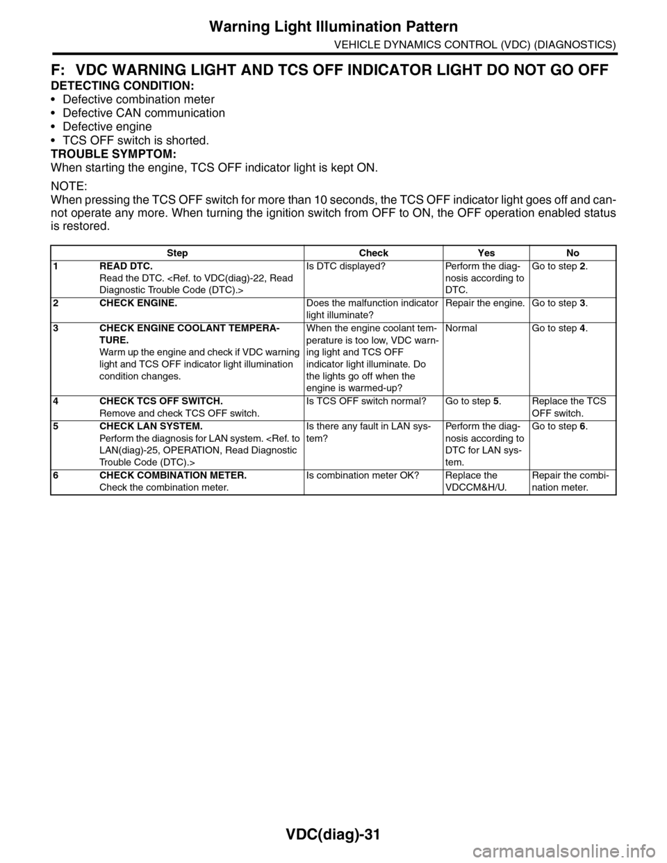
F: VDC WARNING LIGHT AND TCS OFF INDICATOR LIGHT DO NOT GO OFF
DETECTING CONDITION:
•Defective combination meter
•Defective CAN communication
•Defective engine
•TCS OFF switch is shorted.
TROUBLE SYMPTOM:
When starting the engine, TCS OFF indicator light is kept ON.
NOTE:
When pressing the TCS OFF switch for more than 10 seconds, the TCS OFF indicator light goes off and can-
not operate any more. When turning the ignition switch from OFF to ON, the OFF operation enabled status
is restored.
Step Check Yes No
1READ DTC.
Read the DTC.
Is DTC displayed? Perform the diag-
nosis according to
DTC.
Go to step 2.
2CHECK ENGINE.Does the malfunction indicator
light illuminate?
Repair the engine. Go to step 3.
3CHECK ENGINE COOLANT TEMPERA-
TURE.
War m up the engine and check if VDC war ning
light and TCS OFF indicator light illumination
condition changes.
When the engine coolant tem-
perature is too low, VDC warn-
ing light and TCS OFF
indicator light illuminate. Do
the lights go off when the
engine is warmed-up?
Normal Go to step 4.
4CHECK TCS OFF SWITCH.
Remove and check TCS OFF switch.
Is TCS OFF switch normal? Go to step 5.Replace the TCS
OFF switch.
5CHECK LAN SYSTEM.
Perfor m the diagnosis for LAN system.
Tr o u b l e C o d e ( D T C ) . >
Is there any fault in LAN sys-
tem?
Pe r for m t h e d ia g -
nosis according to
DTC for LAN sys-
tem.
Go to step 6.
6CHECK COMBINATION METER.
Check the combination meter.
Is combination meter OK? Replace the
VDCCM&H/U.
Repair the combi-
nation meter.
Page 1040 of 2453
VDC(diag)-48
Diagnostic Procedure with Diagnostic Trouble Code (DTC)
VEHICLE DYNAMICS CONTROL (VDC) (DIAGNOSTICS)
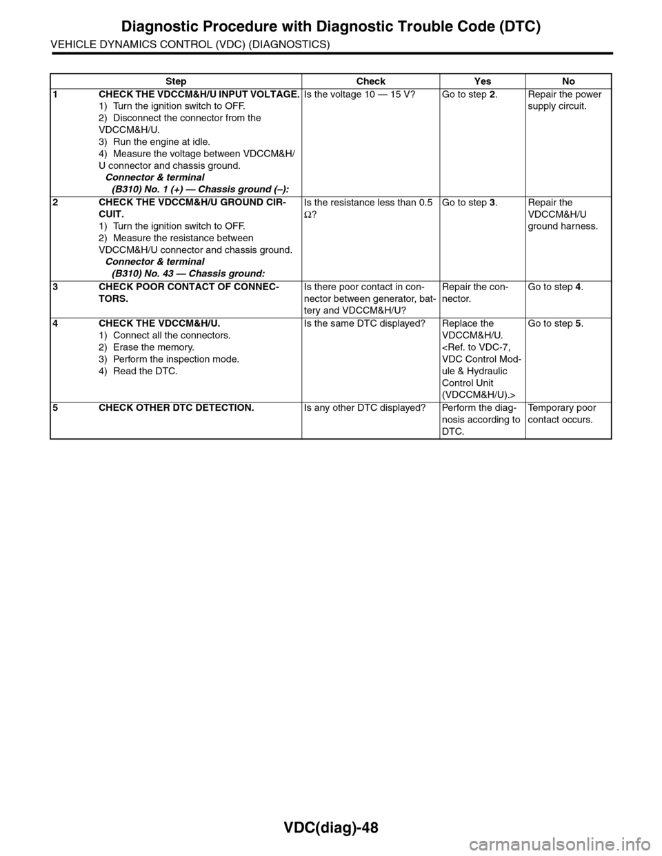
Step Check Yes No
1CHECK THE VDCCM&H/U INPUT VOLTAGE.
1) Turn the ignition switch to OFF.
2) Disconnect the connector from the
VDCCM&H/U.
3) Run the engine at idle.
4) Measure the voltage between VDCCM&H/
U connector and chassis ground.
Connector & terminal
(B310) No. 1 (+) — Chassis ground (–):
Is the voltage 10 — 15 V? Go to step 2.Repair the power
supply circuit.
2CHECK THE VDCCM&H/U GROUND CIR-
CUIT.
1) Turn the ignition switch to OFF.
2) Measure the resistance between
VDCCM&H/U connector and chassis ground.
Connector & terminal
(B310) No. 43 — Chassis ground:
Is the resistance less than 0.5
Ω?
Go to step 3.Repair the
VDCCM&H/U
ground harness.
3CHECK POOR CONTACT OF CONNEC-
TORS.
Is there poor contact in con-
nector between generator, bat-
tery and VDCCM&H/U?
Repair the con-
nector.
Go to step 4.
4CHECK THE VDCCM&H/U.
1) Connect all the connectors.
2) Erase the memory.
3) Perform the inspection mode.
4) Read the DTC.
Is the same DTC displayed? Replace the
VDCCM&H/U.
ule & Hydraulic
Control Unit
(VDCCM&H/U).>
Go to step 5.
5CHECK OTHER DTC DETECTION.Is any other DTC displayed? Perform the diag-
nosis according to
DTC.
Te m p o r a r y p o o r
contact occurs.
Page 1043 of 2453
VDC(diag)-51
Diagnostic Procedure with Diagnostic Trouble Code (DTC)
VEHICLE DYNAMICS CONTROL (VDC) (DIAGNOSTICS)
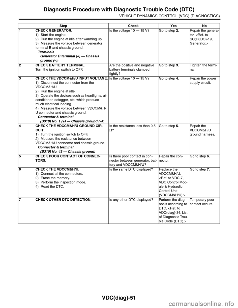
Step Check Yes No
1CHECK GENERATOR.
1) Start the engine.
2) Run the engine at idle after warming up.
3) Measure the voltage between generator
terminal B and chassis ground.
Te r m i n a l s
Generator B terminal (+) — Chassis
ground (–):
Is the voltage 10 — 15 V? Go to step 2.Repair the genera-
tor.
Generator.>
2CHECK BATTERY TERMINAL.
Tu r n t h e i g n i t i o n s w i t c h t o O F F.
Are the positive and negative
battery terminals clamped
tightly?
Go to step 3.Tighten the termi-
nal.
3CHECK THE VDCCM&H/U INPUT VOLTAGE.
1) Disconnect the connector from the
VDCCM&H/U.
2) Run the engine at idle.
3) Operate the devices such as headlights, air
conditioner, defogger, etc. which produce
much electrical loading.
4) Measure the voltage between VDCCM&H/
U connector and chassis ground.
Connector & terminal
(B310) No. 1 (+) — Chassis ground (–):
Is the voltage 10 — 15 V? Go to step 4.Repair the power
supply circuit.
4CHECK THE VDCCM&H/U GROUND CIR-
CUIT.
1) Turn the ignition switch to OFF.
2) Measure the resistance between
VDCCM&H/U connector and chassis ground.
Connector & terminal
(B310) No. 43 — Chassis ground:
Is the resistance less than 0.5
Ω?
Go to step 5.Repair the
VDCCM&H/U
ground harness.
5CHECK POOR CONTACT OF CONNEC-
TORS.
Is there poor contact in con-
nector between generator, bat-
tery and VDCCM&H/U?
Repair the con-
nector.
Go to step 6.
6CHECK THE VDCCM&H/U.
1) Connect all the connectors.
2) Erase the memory.
3) Perform the inspection mode.
4) Read the DTC.
Is the same DTC displayed? Replace the
VDCCM&H/U.
ule & Hydraulic
Control Unit
(VDCCM&H/U).>
Go to step 7.
7CHECK OTHER DTC DETECTION.Is any other DTC displayed? Perform the diag-
nosis according to
DTC.
of Diagnostic Trou-
ble Code (DTC).>
Te m p o r a r y p o o r
contact occurs.
Page 1046 of 2453
VDC(diag)-54
Diagnostic Procedure with Diagnostic Trouble Code (DTC)
VEHICLE DYNAMICS CONTROL (VDC) (DIAGNOSTICS)
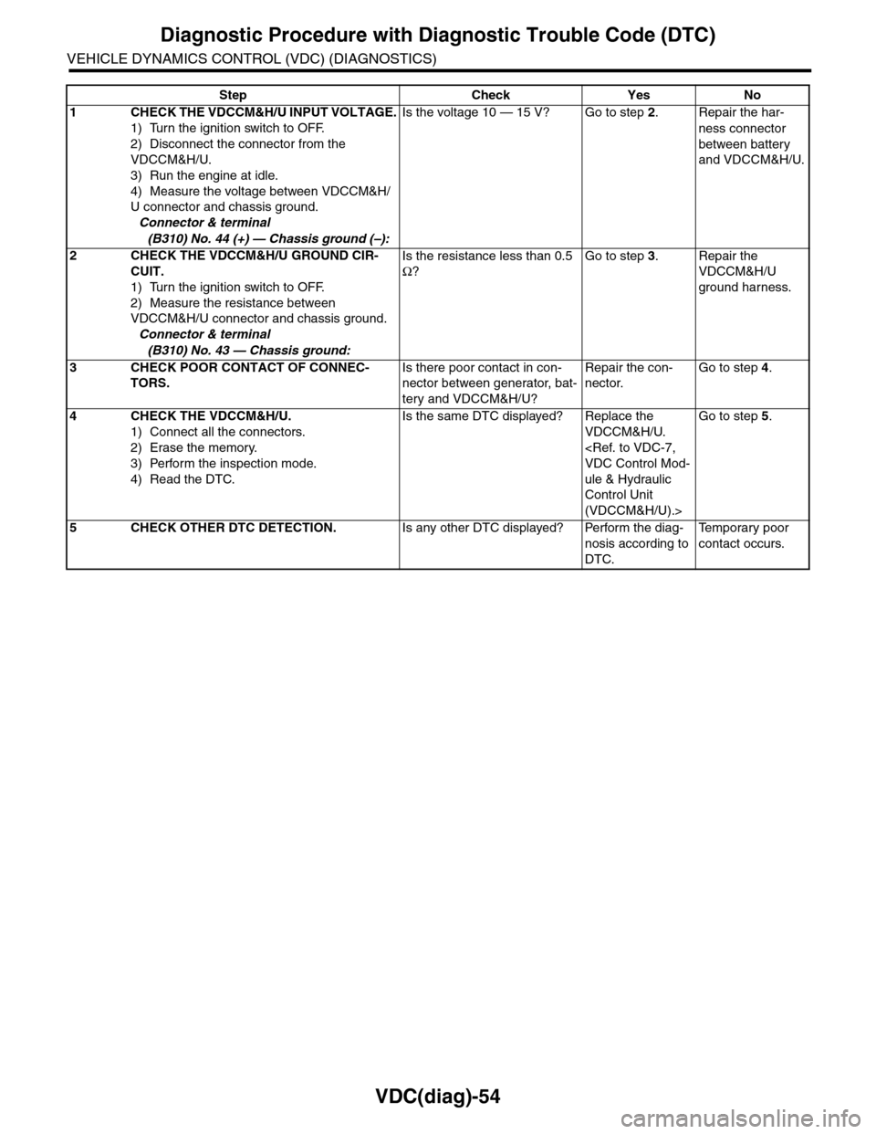
Step Check Yes No
1CHECK THE VDCCM&H/U INPUT VOLTAGE.
1) Turn the ignition switch to OFF.
2) Disconnect the connector from the
VDCCM&H/U.
3) Run the engine at idle.
4) Measure the voltage between VDCCM&H/
U connector and chassis ground.
Connector & terminal
(B310) No. 44 (+) — Chassis ground (–):
Is the voltage 10 — 15 V? Go to step 2.Repair the har-
ness connector
between battery
and VDCCM&H/U.
2CHECK THE VDCCM&H/U GROUND CIR-
CUIT.
1) Turn the ignition switch to OFF.
2) Measure the resistance between
VDCCM&H/U connector and chassis ground.
Connector & terminal
(B310) No. 43 — Chassis ground:
Is the resistance less than 0.5
Ω?
Go to step 3.Repair the
VDCCM&H/U
ground harness.
3CHECK POOR CONTACT OF CONNEC-
TORS.
Is there poor contact in con-
nector between generator, bat-
tery and VDCCM&H/U?
Repair the con-
nector.
Go to step 4.
4CHECK THE VDCCM&H/U.
1) Connect all the connectors.
2) Erase the memory.
3) Perform the inspection mode.
4) Read the DTC.
Is the same DTC displayed? Replace the
VDCCM&H/U.
ule & Hydraulic
Control Unit
(VDCCM&H/U).>
Go to step 5.
5CHECK OTHER DTC DETECTION.Is any other DTC displayed? Perform the diag-
nosis according to
DTC.
Te m p o r a r y p o o r
contact occurs.
Page 1064 of 2453
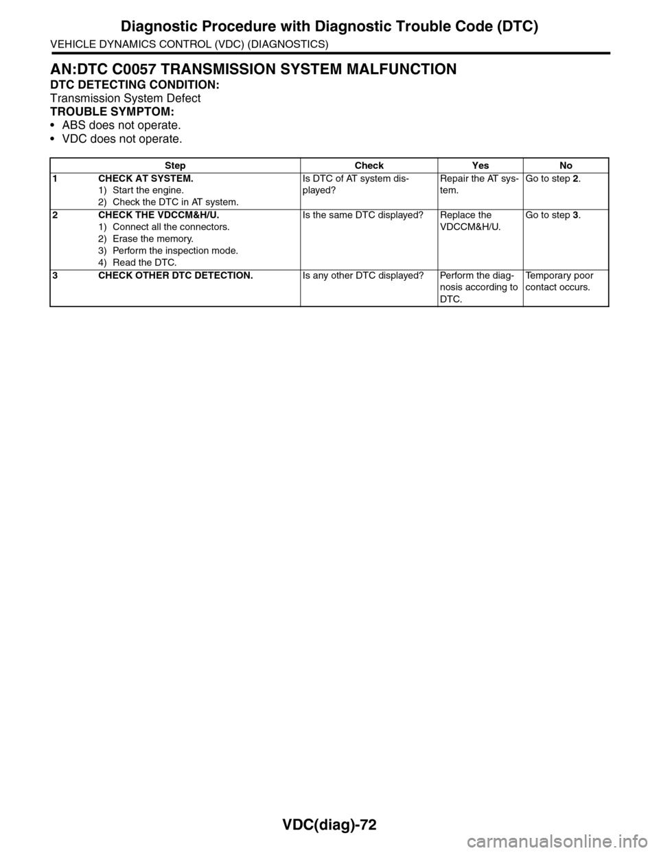
VDC(diag)-72
Diagnostic Procedure with Diagnostic Trouble Code (DTC)
VEHICLE DYNAMICS CONTROL (VDC) (DIAGNOSTICS)
AN:DTC C0057 TRANSMISSION SYSTEM MALFUNCTION
DTC DETECTING CONDITION:
Transmission System Defect
TROUBLE SYMPTOM:
•ABS does not operate.
•VDC does not operate.
Step Check Yes No
1CHECK AT SYSTEM.
1) Start the engine.
2) Check the DTC in AT system.
Is DTC of AT system dis-
played?
Repair the AT sys-
tem.
Go to step 2.
2CHECK THE VDCCM&H/U.
1) Connect all the connectors.
2) Erase the memory.
3) Perform the inspection mode.
4) Read the DTC.
Is the same DTC displayed? Replace the
VDCCM&H/U.
Go to step 3.
3CHECK OTHER DTC DETECTION.Is any other DTC displayed? Perform the diag-
nosis according to
DTC.
Te m p o r a r y p o o r
contact occurs.
Page 1102 of 2453
VDC-21
Front ABS Wheel Speed Sensor
VEHICLE DYNAMICS CONTROL (VDC)
7. Front ABS Wheel Speed Sen-
sor
A: REMOVAL
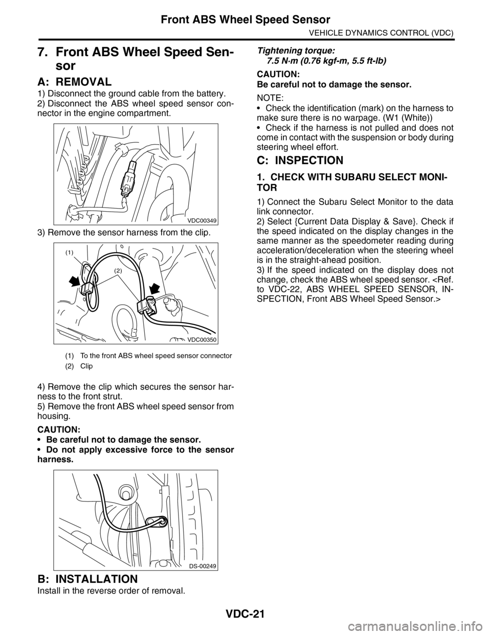
1) Disconnect the ground cable from the battery.
2) Disconnect the ABS wheel speed sensor con-
nector in the engine compartment.
3) Remove the sensor harness from the clip.
4) Remove the clip which secures the sensor har-
ness to the front strut.
5) Remove the front ABS wheel speed sensor from
housing.
CAUTION:
•Be careful not to damage the sensor.
•Do not apply excessive force to the sensor
harness.
B: INSTALLATION
Install in the reverse order of removal.
Tightening torque:
7.5 N·m (0.76 kgf-m, 5.5 ft-lb)
CAUTION:
Be careful not to damage the sensor.
NOTE:
•Check the identification (mark) on the harness to
make sure there is no warpage. (W1 (White))
•Check if the harness is not pulled and does not
come in contact with the suspension or body during
steering wheel effort.
C: INSPECTION
1. CHECK WITH SUBARU SELECT MONI-
TOR
1) Connect the Subaru Select Monitor to the data
link connector.
2) Select {Current Data Display & Save}. Check if
the speed indicated on the display changes in the
same manner as the speedometer reading during
acceleration/deceleration when the steering wheel
is in the straight-ahead position.
3) If the speed indicated on the display does not
change, check the ABS wheel speed sensor.
SPECTION, Front ABS Wheel Speed Sensor.>
(1) To the front ABS wheel speed sensor connector
(2) Clip
VDC00349
VDC00350
(1)
(2)
DS-00249
Page 1127 of 2453
CO(H6DO)-8
Radiator Fan System
COOLING
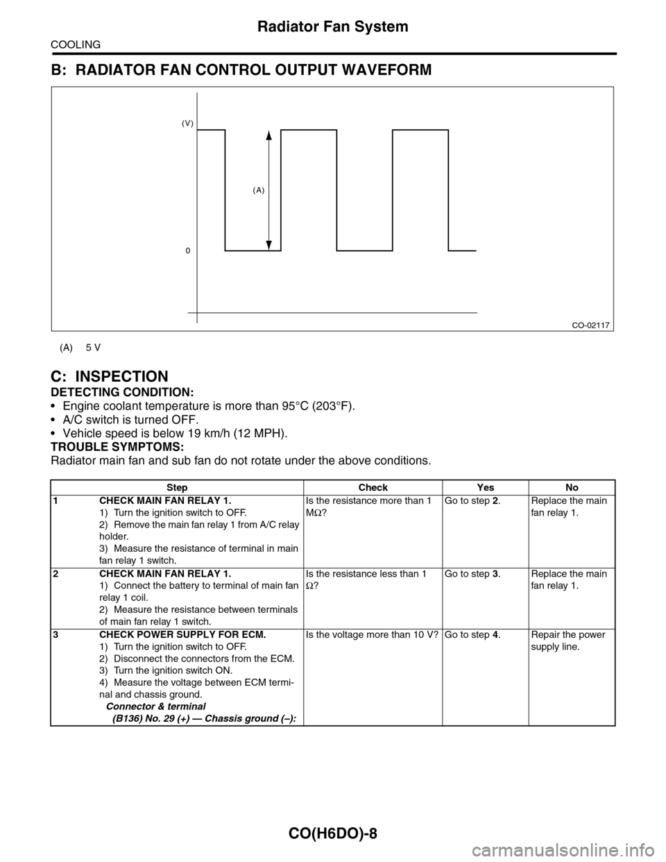
B: RADIATOR FAN CONTROL OUTPUT WAVEFORM
C: INSPECTION
DETECTING CONDITION:
•Engine coolant temperature is more than 95°C (203°F).
•A/C switch is turned OFF.
•Vehicle speed is below 19 km/h (12 MPH).
TROUBLE SYMPTOMS:
Radiator main fan and sub fan do not rotate under the above conditions.
(A) 5 V
Step Check Yes No
1CHECK MAIN FAN RELAY 1.
1) Turn the ignition switch to OFF.
2) Remove the main fan relay 1 from A/C relay
holder.
3) Measure the resistance of terminal in main
fan relay 1 switch.
Is the resistance more than 1
MΩ?
Go to step 2.Replace the main
fan relay 1.
2CHECK MAIN FAN RELAY 1.
1) Connect the battery to terminal of main fan
relay 1 coil.
2) Measure the resistance between terminals
of main fan relay 1 switch.
Is the resistance less than 1
Ω?
Go to step 3.Replace the main
fan relay 1.
3CHECK POWER SUPPLY FOR ECM.
1) Turn the ignition switch to OFF.
2) Disconnect the connectors from the ECM.
3) Turn the ignition switch ON.
4) Measure the voltage between ECM termi-
nal and chassis ground.
Connector & terminal
(B136) No. 29 (+) — Chassis ground (–):
Is the voltage more than 10 V? Go to step 4.Repair the power
supply line.
CO-02117
(V)
0
(A)
Page 1128 of 2453
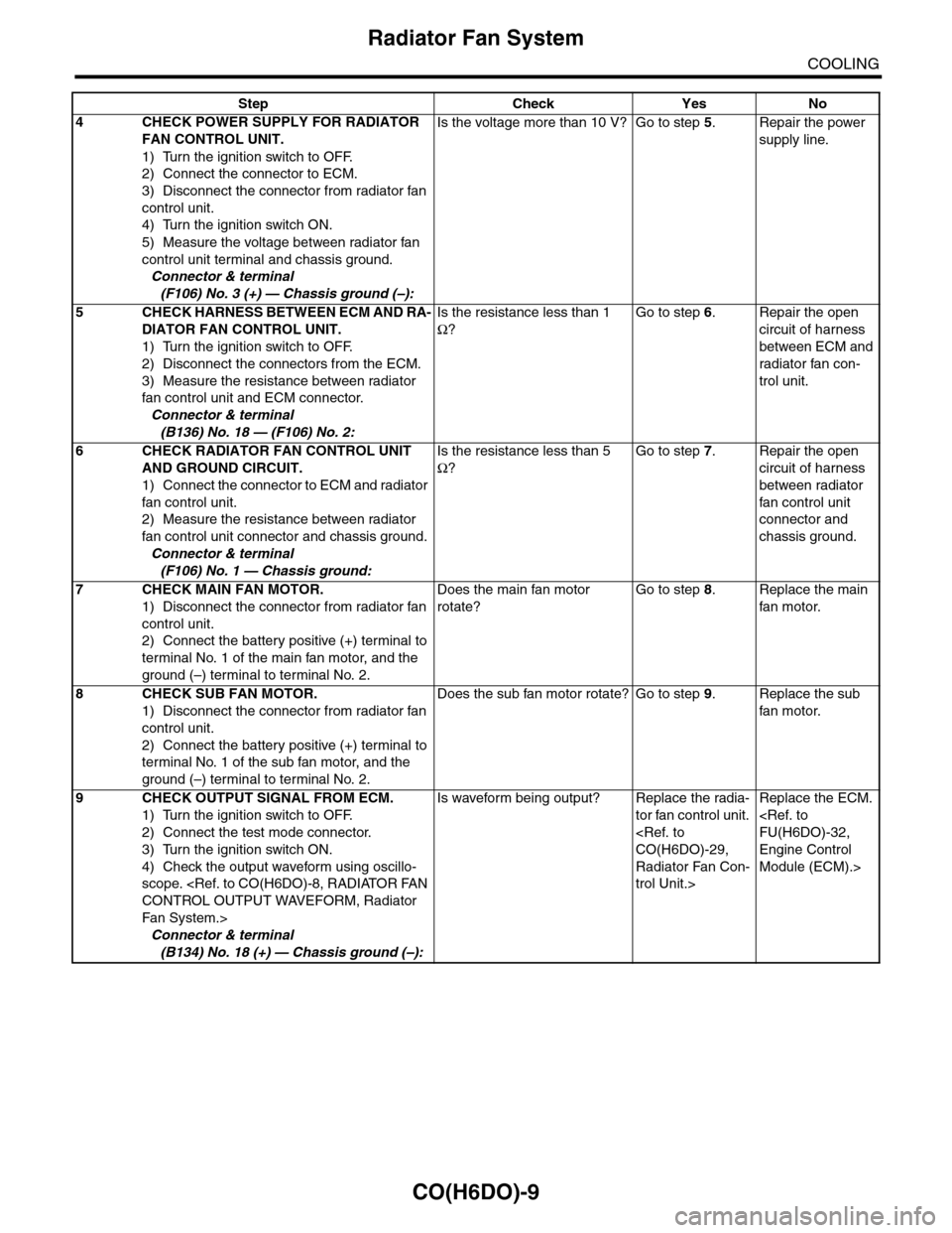
CO(H6DO)-9
Radiator Fan System
COOLING
4CHECK POWER SUPPLY FOR RADIATOR
FAN CONTROL UNIT.
1) Turn the ignition switch to OFF.
2) Connect the connector to ECM.
3) Disconnect the connector from radiator fan
control unit.
4) Turn the ignition switch ON.
5) Measure the voltage between radiator fan
control unit terminal and chassis ground.
Connector & terminal
(F106) No. 3 (+) — Chassis ground (–):
Is the voltage more than 10 V? Go to step 5.Repair the power
supply line.
5CHECK HARNESS BETWEEN ECM AND RA-
DIATOR FAN CONTROL UNIT.
1) Turn the ignition switch to OFF.
2) Disconnect the connectors from the ECM.
3) Measure the resistance between radiator
fan control unit and ECM connector.
Connector & terminal
(B136) No. 18 — (F106) No. 2:
Is the resistance less than 1
Ω?
Go to step 6.Repair the open
circuit of harness
between ECM and
radiator fan con-
trol unit.
6CHECK RADIATOR FAN CONTROL UNIT
AND GROUND CIRCUIT.
1) Connect the connector to ECM and radiator
fan control unit.
2) Measure the resistance between radiator
fan control unit connector and chassis ground.
Connector & terminal
(F106) No. 1 — Chassis ground:
Is the resistance less than 5
Ω?
Go to step 7.Repair the open
circuit of harness
between radiator
fan control unit
connector and
chassis ground.
7CHECK MAIN FAN MOTOR.
1) Disconnect the connector from radiator fan
control unit.
2) Connect the battery positive (+) terminal to
terminal No. 1 of the main fan motor, and the
ground (–) terminal to terminal No. 2.
Does the main fan motor
rotate?
Go to step 8.Replace the main
fan motor.
8CHECK SUB FAN MOTOR.
1) Disconnect the connector from radiator fan
control unit.
2) Connect the battery positive (+) terminal to
terminal No. 1 of the sub fan motor, and the
ground (–) terminal to terminal No. 2.
Does the sub fan motor rotate? Go to step 9.Replace the sub
fan motor.
9CHECK OUTPUT SIGNAL FROM ECM.
1) Turn the ignition switch to OFF.
2) Connect the test mode connector.
3) Turn the ignition switch ON.
4) Check the output waveform using oscillo-
scope.
Fa n S y st e m. >
Connector & terminal
(B134) No. 18 (+) — Chassis ground (–):
Is waveform being output? Replace the radia-
tor fan control unit.
Radiator Fan Con-
trol Unit.>
Replace the ECM.
Engine Control
Module (ECM).>
Step Check Yes No