2009 SUBARU TRIBECA check engine
[x] Cancel search: check enginePage 998 of 2453

VDC(diag)-6
Check List for Interview
VEHICLE DYNAMICS CONTROL (VDC) (DIAGNOSTICS)
3. STATE OF VDC INDICATOR LIGHT
VDC indicator light
comes on. Always
Sometimes
Only once
Does not come on
• When/How long does it come on?
Ignition key position LOCK
ACC
ON (before starting engine)
START
ON (after starting engine, while engine is running)
ON (after starting engine, engine is stop)
Timing Immediately after turning the ignition switch to ON
Immediately after turning the ignition switch to START
Accelerating — km/h
—
MPH
While traveling at a constant speedkm/h MPH
Reducing speed — km/h
— MPH
When turning to the rightSteering angle: deg
Steering time: Sec.
When turning to the leftSteering angle: deg
Steering time: Sec.
When operating other electrical parts
• Part name:
• Operating condition:
Page 1008 of 2453
VDC(diag)-16
Subaru Select Monitor
VEHICLE DYNAMICS CONTROL (VDC) (DIAGNOSTICS)
6. Subaru Select Monitor
A: OPERATION
1. READ DIAGNOSTIC TROUBLE CODE
(DTC)
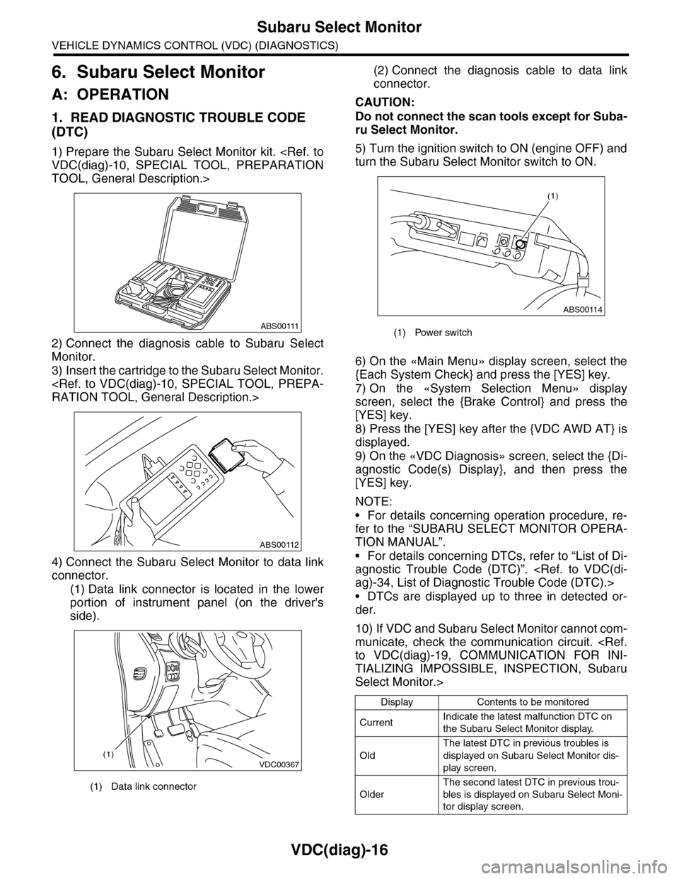
1) Prepare the Subaru Select Monitor kit.
TOOL, General Description.>
2) Connect the diagnosis cable to Subaru Select
Monitor.
3) Insert the cartridge to the Subaru Select Monitor.
4) Connect the Subaru Select Monitor to data link
connector.
(1) Data link connector is located in the lower
portion of instrument panel (on the driver's
side).
(2) Connect the diagnosis cable to data link
connector.
CAUTION:
Do not connect the scan tools except for Suba-
ru Select Monitor.
5) Turn the ignition switch to ON (engine OFF) and
turn the Subaru Select Monitor switch to ON.
6) On the «Main Menu» display screen, select the
{Each System Check} and press the [YES] key.
7) On the «System Selection Menu» display
screen, select the {Brake Control} and press the
[YES] key.
8) Press the [YES] key after the {VDC AWD AT} is
displayed.
9) On the «VDC Diagnosis» screen, select the {Di-
agnostic Code(s) Display}, and then press the
[YES] key.
NOTE:
•For details concerning operation procedure, re-
fer to the “SUBARU SELECT MONITOR OPERA-
TION MANUAL”.
•For details concerning DTCs, refer to “List of Di-
agnostic Trouble Code (DTC)”.
•DTCs are displayed up to three in detected or-
der.
10) If VDC and Subaru Select Monitor cannot com-
municate, check the communication circuit.
TIALIZING IMPOSSIBLE, INSPECTION, Subaru
Select Monitor.>
(1) Data link connector
ABS00111
ABS00112
VDC00367(1)
(1) Power switch
Display Contents to be monitored
CurrentIndicate the latest malfunction DTC on
the Subaru Select Monitor display.
Old
The latest DTC in previous troubles is
displayed on Subaru Select Monitor dis-
play screen.
Older
The second latest DTC in previous trou-
bles is displayed on Subaru Select Moni-
tor display screen.
ABS00114
(1)
Page 1009 of 2453
![SUBARU TRIBECA 2009 1.G Service Workshop Manual VDC(diag)-17
Subaru Select Monitor
VEHICLE DYNAMICS CONTROL (VDC) (DIAGNOSTICS)
2. READ CURRENT DATA
1) On the «Main Menu» display screen, select the {Each System Check} and press the [YES] key.
2) SUBARU TRIBECA 2009 1.G Service Workshop Manual VDC(diag)-17
Subaru Select Monitor
VEHICLE DYNAMICS CONTROL (VDC) (DIAGNOSTICS)
2. READ CURRENT DATA
1) On the «Main Menu» display screen, select the {Each System Check} and press the [YES] key.
2)](/manual-img/17/7322/w960_7322-1008.png)
VDC(diag)-17
Subaru Select Monitor
VEHICLE DYNAMICS CONTROL (VDC) (DIAGNOSTICS)
2. READ CURRENT DATA
1) On the «Main Menu» display screen, select the {Each System Check} and press the [YES] key.
2) On the «System Selection Menu» display screen, select the {Brake Control} and press the [YES] key.
3) Press the [YES] key after {VDC AWD AT} is displayed.
4) On the «Brake Control Diagnosis» display screen, select the {Current Data Display/Save}, and then press
the [YES] key.
5) On the «Display Menu» screen, select the data display method and press the [YES] key.
6) Using a scroll key, scroll the display screen up or down until necessary data is shown.
•A list of the support data is shown in the following table.
NOTE:
For details concerning operation procedure, refer to the “SUBARU SELECT MONITOR OPERATION MAN-
UAL”.
Display Contents to be monitored Unit of measure
FR Wheel SpeedWheel speed detected by front ABS wheel speed sensor RH is dis-
played.km/h or MPH
FL Wheel SpeedWheel speed detected by front ABS wheel speed sensor LH is dis-
played.km/h or MPH
RR Wheel SpeedWheel speed detected by rear ABS wheel speed sensor RH is dis-
played.km/h or MPH
RL Wheel SpeedWheel speed detected by rear ABS wheel speed sensor LH is dis-
played.km/h or MPH
Fr o nt / Re ar G S e ns o r Ve h ic le f r on t / re a r ac ce le ra t io n d e te c te d by G se n so r is d i sp layed .m/s2
Lateral G Sensor Vehicle lateral acceleration detected by G sensor is displayed.m/s2
IG power supply voltage Voltage supplied to VDCCM&H/U is displayed. V
Steering Angle Sensor Steering angle detected by steering angle sensor is displayed. deg
Ya w R a t e S e n s o r V e h i c l e a n g u l a r s p e e d d e t e c t e d b y y a w r a t e s e n s o r i s d i s p l a y e d . d e g / s
Pressure Sensor Brake fluid pressure detected by pressure sensor is displayed. bar
ABS Control Flag ABS control condition is displayed. ON or OFF
EBD Control Flag EBD control condition is displayed. ON or OFF
Brake Switch Brake ON/OFF is displayed. ON or OFF
ABS Warning Light ON operation of the ABS warning light is displayed. ON or OFF
EBD Warning Light ON operation of the EBD warning light is displayed. ON or OFF
Motor Relay Signal Motor relay operation signal is displayed. ON or OFF
Motor Relay Monitor Motor relay monitor signal is displayed. ON or OFF
TCS Control Flag TCS control condition is displayed. ON or OFF
Va l ve R e l ay S i g n a l Va l v e r e l ay o p e r a t i o n s i g n a l i s d i s p l ay e d . O N o r O F F
VDC Control Flag VDC control condition is displayed. ON or OFF
VDC Warning Light ON operation of the VDC warning light is displayed. ON or OFF
OFF Light ON/OFF condition of TCS OFF indicator light is displayed. ON or OFF
E/G Control Prohibited Flag Engine control command signal is displayed. 1 or 0
OFF Switch Signal Operation condition of TCS OFF switch is displayed. ON or OFF
Motor Fail Safe Relay Drive
SignalMotor fail safe relay drive signal is displayed. ON or OFF
Page 1010 of 2453
![SUBARU TRIBECA 2009 1.G Service Workshop Manual VDC(diag)-18
Subaru Select Monitor
VEHICLE DYNAMICS CONTROL (VDC) (DIAGNOSTICS)
3. CLEAR MEMORY MODE
1) On the «Main Menu», select the {2. Each Sys-
tem Check} and press the [YES] key.
2) On SUBARU TRIBECA 2009 1.G Service Workshop Manual VDC(diag)-18
Subaru Select Monitor
VEHICLE DYNAMICS CONTROL (VDC) (DIAGNOSTICS)
3. CLEAR MEMORY MODE
1) On the «Main Menu», select the {2. Each Sys-
tem Check} and press the [YES] key.
2) On](/manual-img/17/7322/w960_7322-1009.png)
VDC(diag)-18
Subaru Select Monitor
VEHICLE DYNAMICS CONTROL (VDC) (DIAGNOSTICS)
3. CLEAR MEMORY MODE
1) On the «Main Menu», select the {2. Each Sys-
tem Check} and press the [YES] key.
2) On the «System Selection Menu» display
screen, select the {Brake Control} and press the
[YES] key.
3) Press the [YES] key after {VDC AWD AT} is dis-
played.
4) On the «Brake Control Diagnosis» display
screen, select the {Memory Clear} and press the
[YES] key.
5) When “Done” and “Turn ignition switch OFF” are
shown on the display screen, turn the Subaru Se-
lect Monitor and ignition switch to OFF.
NOTE:
For details concerning operation procedure, refer
to the “SUBARU SELECT MONITOR OPERATION
MANUAL”.
4. SEQUENCE CONTROL
5. FREEZE FRAME DATA
NOTE:
•Data stored at the time of trouble occurrence is
shown on display.
•Each time trouble occurs, the latest information
is stored in the freeze frame data in memory.
Display Contents to be monitored
Clear memory? DTC deleting function
Display Contents to be monitoredReference tar-
get
ABS
sequence
control
Operate the valve and
pump motor continuously
to perform the ABS
sequence control.
Sequence Con-
trol.>
VDC
sequence
control
Operate the valve and
pump motor continuously
to perform the VDC
sequence control.
Sequence Con-
trol.>
Display Contents to be monitored
IG CounterNumber of times ignition switch turned to
ON is displayed.
DTC The recorded failure code is displayed.
FR Wheel
Speed
Wheel speed detected by front ABS
wheel speed sensor RH is displayed in
km/h or MPH.
FL Wheel Speed
Wheel speed detected by front ABS
wheel speed sensor LH is displayed in
km/h or MPH.
RR Wheel
Speed
Wheel speed detected by rear ABS
wheel speed sensor RH is displayed in
km/h or MPH.
RL Wheel
Speed
Wheel speed detected by rear ABS
wheel speed sensor LH is displayed in
km/h or MPH.
Ve h i c l e S p e e dVe h i c l e s p e e d c a l c u l a t e d b y V D C c o n t r o l
module is displayed.
G Sensor First
ShaftThe sensor value for a 45° angle crossed
2 axis G sensor is displayed.G Sensor Sec-
ond Shaft
Ya w R a t e S e n -
sor
Ve h i c l e a n g u l a r s p e e d d e t e c t e d b y y a w
rate sensor is displayed.
IG power supply
voltage
Vo l t a g e s u p p l i e d t o V D C c o n t r o l m o d u l e
is displayed.
Steering Angle
Sensor
Steering angle detected by steering
angle sensor is displayed.
Pressure sen-
sor output
Brake fluid pressure detected by pres-
sure sensor is displayed.
Engine SpeedEngine speed on malfunction occur-
rence is displayed.
Acceleration
Opening AngleAcceleration opening is displayed.
Gear positionGear position on malfunction occurrence
is displayed.
Steering Angle
Sensor Malfunc-
tion Code
The recorded steering angle sensor fail-
ure code is displayed?
ABS Control
FlagABS control condition is displayed.
EBD Control
FlagEBD control condition is displayed.
Brake Switch Brake ON/OFF is displayed.
TCS Control
FlagTCS control condition is displayed.
VDC Control
FlagVDC control condition is displayed.
E/G Control Flag
Absolute angle
recognition flag
Whether the absolute angle was deter-
mined is displayed.
OFF Switch Sig-
nal
Operation condition of TCS OFF switch
is displayed.
Page 1012 of 2453
VDC(diag)-20
Subaru Select Monitor
VEHICLE DYNAMICS CONTROL (VDC) (DIAGNOSTICS)
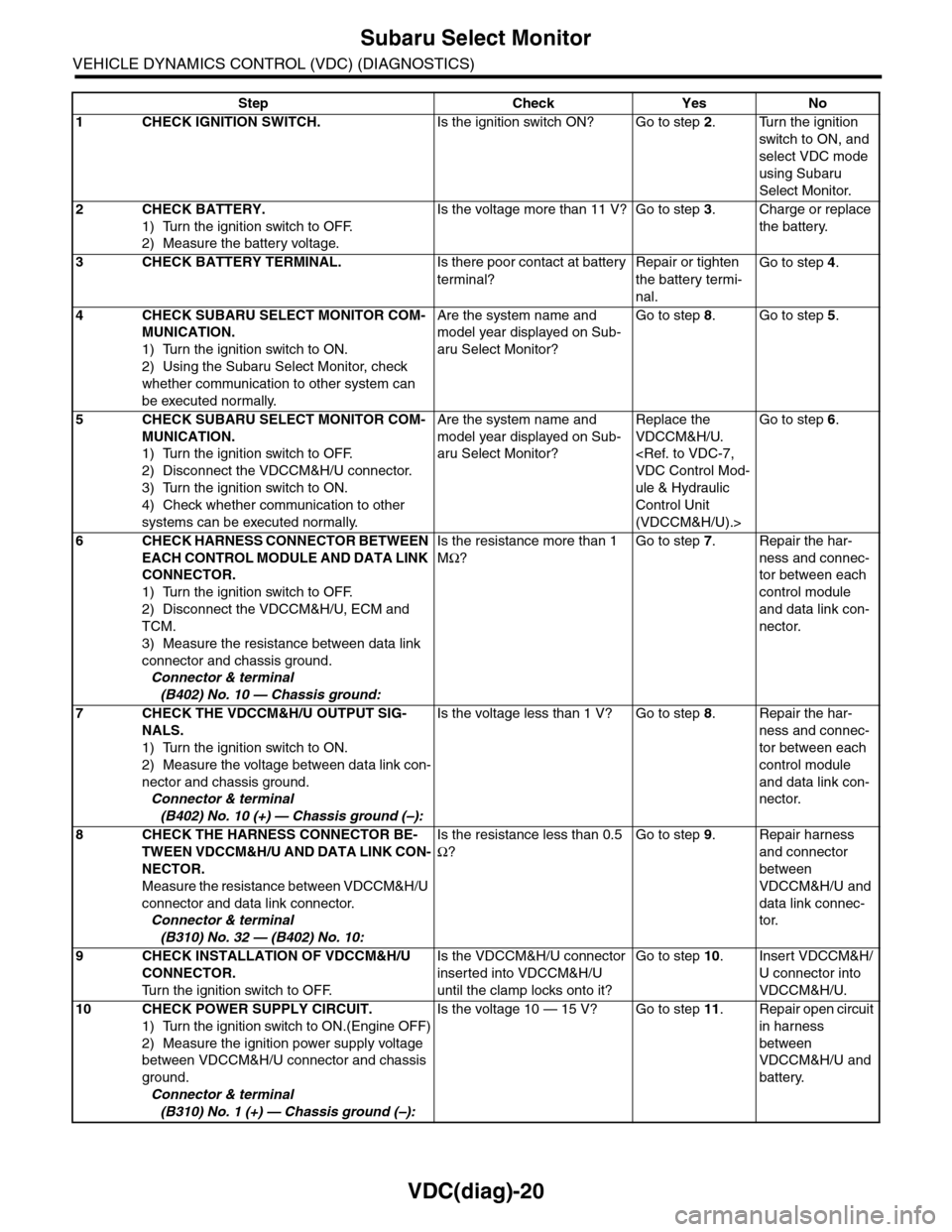
Step Check Yes No
1CHECK IGNITION SWITCH.Is the ignition switch ON? Go to step 2.Turn the ignition
switch to ON, and
select VDC mode
using Subaru
Select Monitor.
2CHECK BATTERY.
1) Turn the ignition switch to OFF.
2) Measure the battery voltage.
Is the voltage more than 11 V? Go to step 3.Charge or replace
the battery.
3CHECK BATTERY TERMINAL.Is there poor contact at battery
terminal?
Repair or tighten
the battery termi-
nal.
Go to step 4.
4CHECK SUBARU SELECT MONITOR COM-
MUNICATION.
1) Turn the ignition switch to ON.
2) Using the Subaru Select Monitor, check
whether communication to other system can
be executed normally.
Are the system name and
model year displayed on Sub-
aru Select Monitor?
Go to step 8.Go to step 5.
5CHECK SUBARU SELECT MONITOR COM-
MUNICATION.
1) Turn the ignition switch to OFF.
2) Disconnect the VDCCM&H/U connector.
3) Turn the ignition switch to ON.
4) Check whether communication to other
systems can be executed normally.
Are the system name and
model year displayed on Sub-
aru Select Monitor?
Replace the
VDCCM&H/U.
ule & Hydraulic
Control Unit
(VDCCM&H/U).>
Go to step 6.
6CHECK HARNESS CONNECTOR BETWEEN
EACH CONTROL MODULE AND DATA LINK
CONNECTOR.
1) Turn the ignition switch to OFF.
2) Disconnect the VDCCM&H/U, ECM and
TCM.
3) Measure the resistance between data link
connector and chassis ground.
Connector & terminal
(B402) No. 10 — Chassis ground:
Is the resistance more than 1
MΩ?
Go to step 7.Repair the har-
ness and connec-
tor between each
control module
and data link con-
nector.
7CHECK THE VDCCM&H/U OUTPUT SIG-
NALS.
1) Turn the ignition switch to ON.
2) Measure the voltage between data link con-
nector and chassis ground.
Connector & terminal
(B402) No. 10 (+) — Chassis ground (–):
Is the voltage less than 1 V? Go to step 8.Repair the har-
ness and connec-
tor between each
control module
and data link con-
nector.
8CHECK THE HARNESS CONNECTOR BE-
TWEEN VDCCM&H/U AND DATA LINK CON-
NECTOR.
Measure the resistance between VDCCM&H/U
connector and data link connector.
Connector & terminal
(B310) No. 32 — (B402) No. 10:
Is the resistance less than 0.5
Ω?
Go to step 9.Repair harness
and connector
between
VDCCM&H/U and
data link connec-
tor.
9CHECK INSTALLATION OF VDCCM&H/U
CONNECTOR.
Tu r n t h e i g n i t i o n s w i t c h t o O F F.
Is the VDCCM&H/U connector
inserted into VDCCM&H/U
until the clamp locks onto it?
Go to step 10.Insert VDCCM&H/
U connector into
VDCCM&H/U.
10 CHECK POWER SUPPLY CIRCUIT.
1) Turn the ignition switch to ON.(Engine OFF)
2) Measure the ignition power supply voltage
between VDCCM&H/U connector and chassis
ground.
Connector & terminal
(B310) No. 1 (+) — Chassis ground (–):
Is the voltage 10 — 15 V? Go to step 11.Repair open circuit
in harness
between
VDCCM&H/U and
battery.
Page 1017 of 2453
VDC(diag)-25
Warning Light Illumination Pattern
VEHICLE DYNAMICS CONTROL (VDC) (DIAGNOSTICS)
10.Warning Light Illumination Pattern
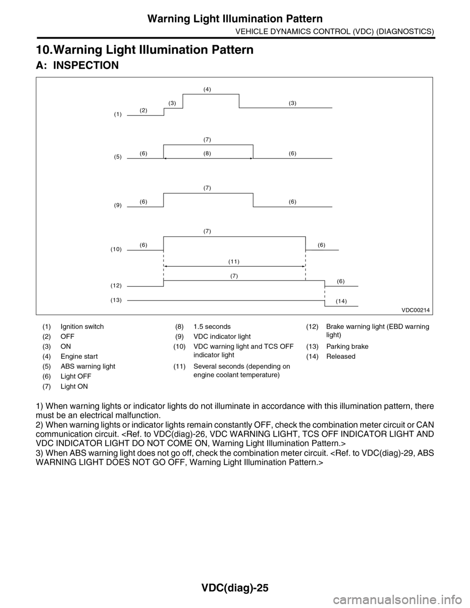
A: INSPECTION
1) When warning lights or indicator lights do not illuminate in accordance with this illumination pattern, there
must be an electrical malfunction.
2) When warning lights or indicator lights remain constantly OFF, check the combination meter circuit or CAN
communication circuit.
3) When ABS warning light does not go off, check the combination meter circuit.
(1) Ignition switch (8) 1.5 seconds (12) Brake warning light (EBD warning
light)(2) OFF (9) VDC indicator light
(3) ON (10) VDC warning light and TCS OFF
indicator light
(13) Parking brake
(4) Engine start (14) Released
(5) ABS warning light (11) Several seconds (depending on
engine coolant temperature)(6) Light OFF
(7) Light ON
VDC00214
(2)
(6) (6)
(7)
(6) (6)
(7)
(8)
(6) (6)
(7)
(11)
(3) (3)
(4)
(1)
(5)
(9)
(10)
(6)(7)
(12)
(14)(13)
Page 1018 of 2453
VDC(diag)-26
Warning Light Illumination Pattern
VEHICLE DYNAMICS CONTROL (VDC) (DIAGNOSTICS)
4) When the VDC indicator light, VDC warning light and TCS OFF indicator light do not go off, check the com-
bination meter circuit or CAN communication circuit.
NOTE:
•Even though the ABS warning light does not go off after 1.5 seconds from ABS warning light illumination,
the ABS system operates normally when the warning light goes off while driving at approximately 12 km/h (7
MPH). However, the ABS system does not work while the ABS warning light is illuminated.
•It may take several minutes before VDC warning light and TCS OFF indicator light goes off if the vehicle
is parked under low temperature for a specified time. This is not defective because it is resulted from low en-
gine coolant temperature.
•With the vehicle jack-up/lift-up or set on free rollers, when the wheels lock or spin after starting the engine,
ABS warning light, VDC warning light and TCS OFF indicator light may illuminate because VDCCM&H/U de-
tects the abnormal conditions from ABS wheel speed sensors. In this case, this is not a malfunction. Perform
the clear memory mode.
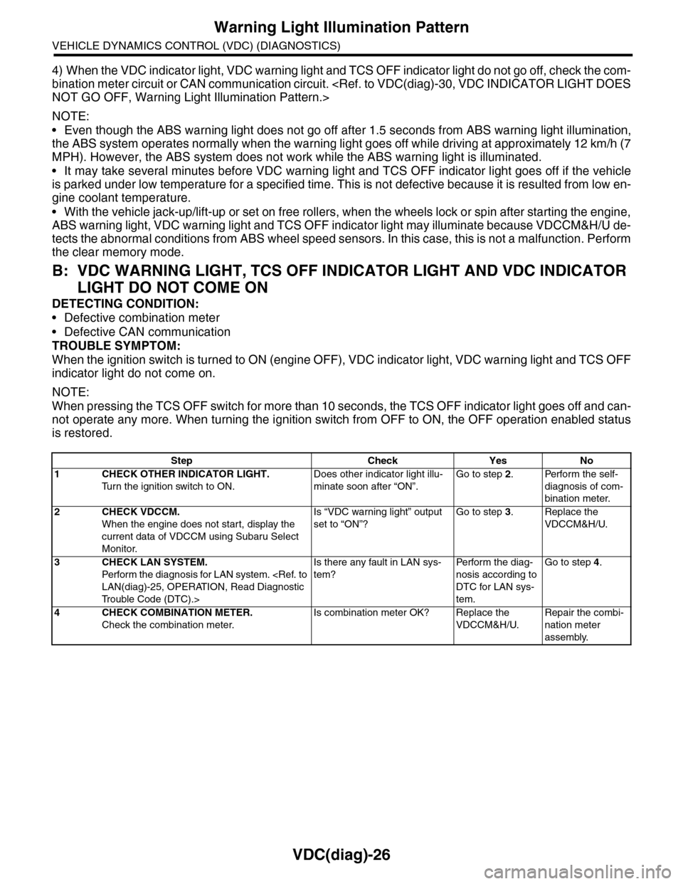
B: VDC WARNING LIGHT, TCS OFF INDICATOR LIGHT AND VDC INDICATOR
LIGHT DO NOT COME ON
DETECTING CONDITION:
•Defective combination meter
•Defective CAN communication
TROUBLE SYMPTOM:
When the ignition switch is turned to ON (engine OFF), VDC indicator light, VDC warning light and TCS OFF
indicator light do not come on.
NOTE:
When pressing the TCS OFF switch for more than 10 seconds, the TCS OFF indicator light goes off and can-
not operate any more. When turning the ignition switch from OFF to ON, the OFF operation enabled status
is restored.
Step Check Yes No
1CHECK OTHER INDICATOR LIGHT.
Tu r n t h e i g n i t i o n s w i t c h t o O N .
Does other indicator light illu-
minate soon after “ON”.
Go to step 2.Perform the self-
diagnosis of com-
bination meter.
2CHECK VDCCM.
When the engine does not start, display the
current data of VDCCM using Subaru Select
Monitor.
Is “VDC warning light” output
set to “ON”?
Go to step 3.Replace the
VDCCM&H/U.
3CHECK LAN SYSTEM.
Perfor m the diagnosis for LAN system.
Tr o u b l e C o d e ( D T C ) . >
Is there any fault in LAN sys-
tem?
Pe r for m t h e d ia g -
nosis according to
DTC for LAN sys-
tem.
Go to step 4.
4CHECK COMBINATION METER.
Check the combination meter.
Is combination meter OK? Replace the
VDCCM&H/U.
Repair the combi-
nation meter
assembly.
Page 1022 of 2453
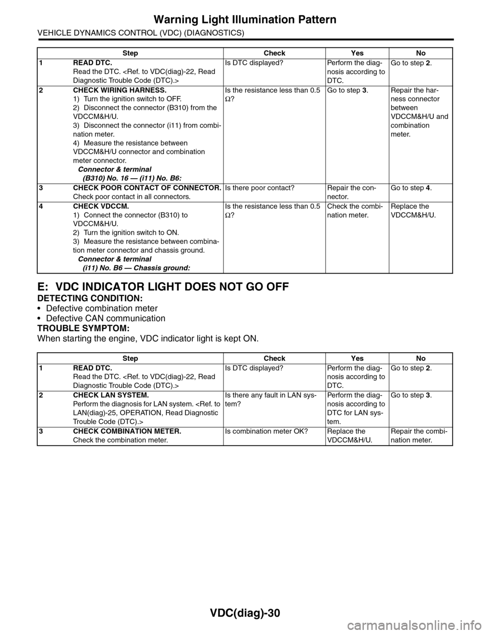
VDC(diag)-30
Warning Light Illumination Pattern
VEHICLE DYNAMICS CONTROL (VDC) (DIAGNOSTICS)
E: VDC INDICATOR LIGHT DOES NOT GO OFF
DETECTING CONDITION:
•Defective combination meter
•Defective CAN communication
TROUBLE SYMPTOM:
When starting the engine, VDC indicator light is kept ON.
Step Check Yes No
1READ DTC.
Read the DTC.
Is DTC displayed? Perform the diag-
nosis according to
DTC.
Go to step 2.
2CHECK WIRING HARNESS.
1) Turn the ignition switch to OFF.
2) Disconnect the connector (B310) from the
VDCCM&H/U.
3) Disconnect the connector (i11) from combi-
nation meter.
4) Measure the resistance between
VDCCM&H/U connector and combination
meter connector.
Connector & terminal
(B310) No. 16 — (i11) No. B6:
Is the resistance less than 0.5
Ω?
Go to step 3.Repair the har-
ness connector
between
VDCCM&H/U and
combination
meter.
3CHECK POOR CONTACT OF CONNECTOR.
Check poor contact in all connectors.
Is there poor contact? Repair the con-
nector.
Go to step 4.
4CHECK VDCCM.
1) Connect the connector (B310) to
VDCCM&H/U.
2) Turn the ignition switch to ON.
3) Measure the resistance between combina-
tion meter connector and chassis ground.
Connector & terminal
(i11) No. B6 — Chassis ground:
Is the resistance less than 0.5
Ω?
Check the combi-
nation meter.
Replace the
VDCCM&H/U.
Step Check Yes No
1READ DTC.
Read the DTC.
Is DTC displayed? Perform the diag-
nosis according to
DTC.
Go to step 2.
2CHECK LAN SYSTEM.
Perfor m the diagnosis for LAN system.
Tr o u b l e C o d e ( D T C ) . >
Is there any fault in LAN sys-
tem?
Pe r for m t h e d ia g -
nosis according to
DTC for LAN sys-
tem.
Go to step 3.
3CHECK COMBINATION METER.
Check the combination meter.
Is combination meter OK? Replace the
VDCCM&H/U.
Repair the combi-
nation meter.