2009 SUBARU TRIBECA check engine
[x] Cancel search: check enginePage 1200 of 2453
EN(H6DO)(diag)-39
Inspection Mode
ENGINE (DIAGNOSTICS)
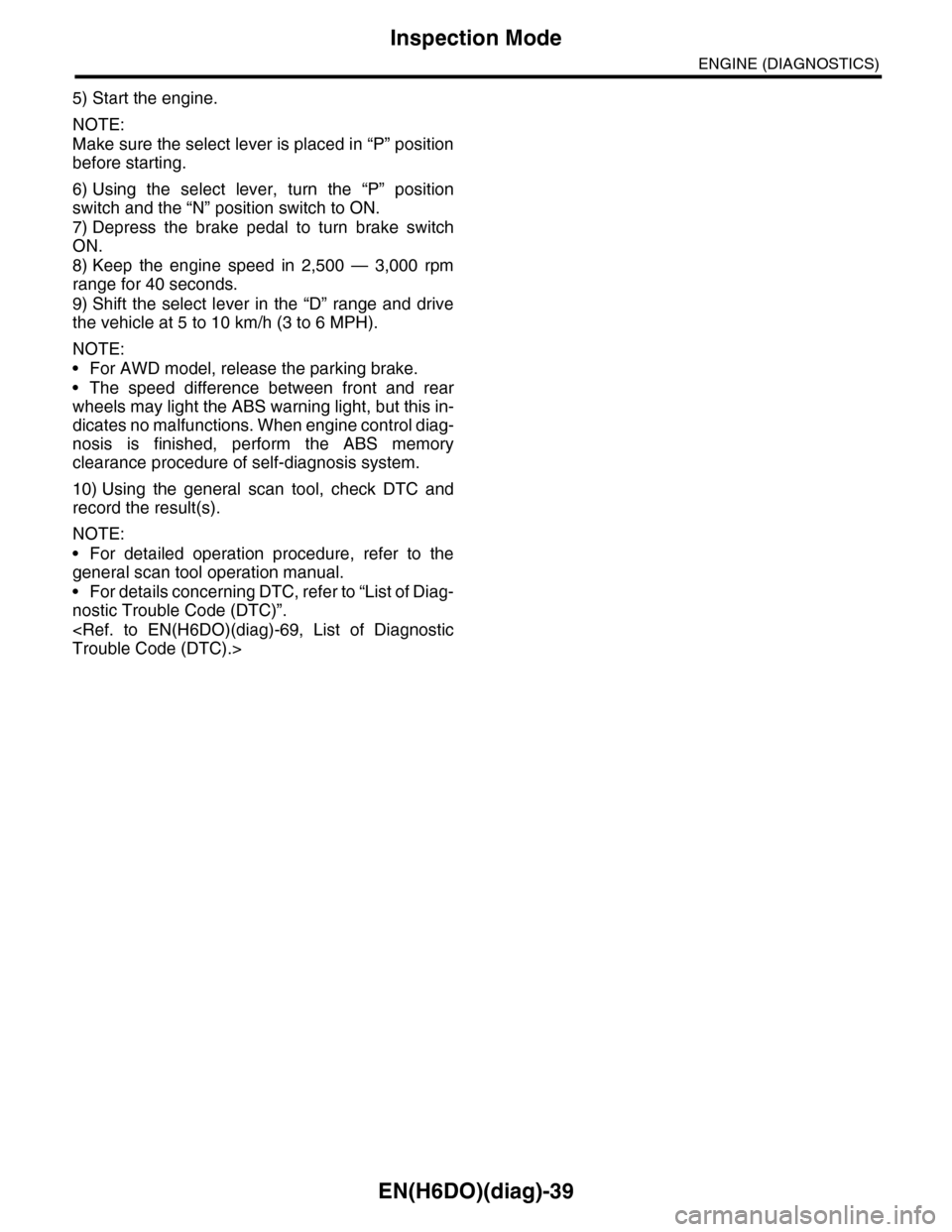
5) Start the engine.
NOTE:
Make sure the select lever is placed in “P” position
before starting.
6) Using the select lever, turn the “P” position
switch and the “N” position switch to ON.
7) Depress the brake pedal to turn brake switch
ON.
8) Keep the engine speed in 2,500 — 3,000 rpm
range for 40 seconds.
9) Shift the select lever in the “D” range and drive
the vehicle at 5 to 10 km/h (3 to 6 MPH).
NOTE:
•For AWD model, release the parking brake.
•The speed difference between front and rear
wheels may light the ABS warning light, but this in-
dicates no malfunctions. When engine control diag-
nosis is finished, perform the ABS memory
clearance procedure of self-diagnosis system.
10) Using the general scan tool, check DTC and
record the result(s).
NOTE:
•For detailed operation procedure, refer to the
general scan tool operation manual.
•For details concerning DTC, refer to “List of Diag-
nostic Trouble Code (DTC)”.
Page 1201 of 2453
EN(H6DO)(diag)-40
Drive Cycle
ENGINE (DIAGNOSTICS)
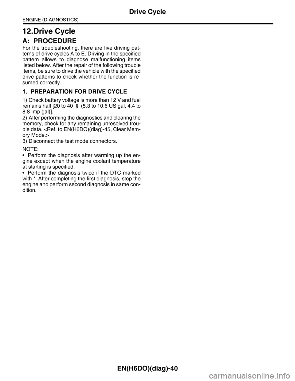
12.Drive Cycle
A: PROCEDURE
For the troubleshooting, there are five driving pat-
terns of drive cycles A to E. Driving in the specified
pattern allows to diagnose malfunctioning items
listed below. After the repair of the following trouble
items, be sure to drive the vehicle with the specified
drive patterns to check whether the function is re-
sumed correctly.
1. PREPARATION FOR DRIVE CYCLE
1) Check battery voltage is more than 12 V and fuel
remains half [20 to 40 2 (5.3 to 10.6 US gal, 4.4 to
8.8 Imp gal)].
2) After performing the diagnostics and clearing the
memory, check for any remaining unresolved trou-
ble data.
3) Disconnect the test mode connectors.
NOTE:
•Perform the diagnosis after warming up the en-
gine except when the engine coolant temperature
at starting is specified.
•Perform the diagnosis twice if the DTC marked
with *. After completing the first diagnosis, stop the
engine and perform second diagnosis in same con-
dition.
Page 1203 of 2453
EN(H6DO)(diag)-42
Drive Cycle
ENGINE (DIAGNOSTICS)
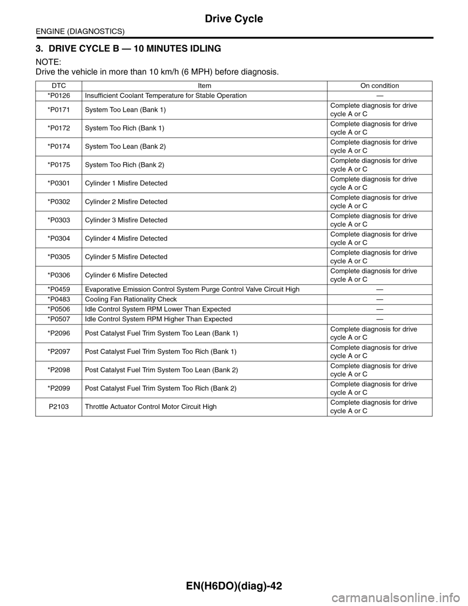
3. DRIVE CYCLE B — 10 MINUTES IDLING
NOTE:
Drive the vehicle in more than 10 km/h (6 MPH) before diagnosis.
DTC Item On condition
*P0126 Insufficient Coolant Temperature for Stable Operation —
*P0171 System Too Lean (Bank 1)Complete diagnosis for drive
cycle A or C
*P0172 System Too Rich (Bank 1)Complete diagnosis for drive
cycle A or C
*P0174 System Too Lean (Bank 2)Complete diagnosis for drive
cycle A or C
*P0175 System Too Rich (Bank 2)Complete diagnosis for drive
cycle A or C
*P0301 Cylinder 1 Misfire DetectedComplete diagnosis for drive
cycle A or C
*P0302 Cylinder 2 Misfire DetectedComplete diagnosis for drive
cycle A or C
*P0303 Cylinder 3 Misfire DetectedComplete diagnosis for drive
cycle A or C
*P0304 Cylinder 4 Misfire DetectedComplete diagnosis for drive
cycle A or C
*P0305 Cylinder 5 Misfire DetectedComplete diagnosis for drive
cycle A or C
*P0306 Cylinder 6 Misfire DetectedComplete diagnosis for drive
cycle A or C
*P0459 Evaporative Emission Control System Purge Control Valve Circuit High —
*P0483 Cooling Fan Rationality Check —
*P0506 Idle Control System RPM Lower Than Expected —
*P0507 Idle Control System RPM Higher Than Expected —
*P2096 Post Catalyst Fuel Trim System Too Lean (Bank 1)Complete diagnosis for drive
cycle A or C
*P2097 Post Catalyst Fuel Trim System Too Rich (Bank 1)Complete diagnosis for drive
cycle A or C
*P2098 Post Catalyst Fuel Trim System Too Lean (Bank 2)Complete diagnosis for drive
cycle A or C
*P2099 Post Catalyst Fuel Trim System Too Rich (Bank 2)Complete diagnosis for drive
cycle A or C
P2103 Throttle Actuator Control Motor Circuit HighComplete diagnosis for drive
cycle A or C
Page 1205 of 2453
EN(H6DO)(diag)-44
Drive Cycle
ENGINE (DIAGNOSTICS)
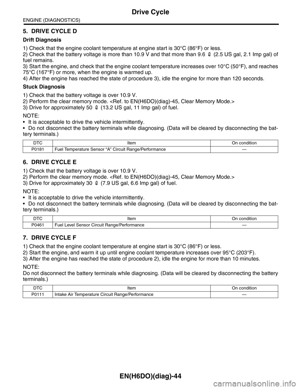
5. DRIVE CYCLE D
Drift Diagnosis
1) Check that the engine coolant temperature at engine start is 30°C (86°F) or less.
2) Check that the battery voltage is more than 10.9 V and that more than 9.6 2 (2.5 US gal, 2.1 Imp gal) of
fuel remains.
3) Start the engine, and check that the engine coolant temperature increases over 10°C (50°F), and reaches
75°C (167°F) or more, when the engine is warmed up.
4) After the engine has reached the state of procedure 3), idle the engine for more than 120 seconds.
Stuck Diagnosis
1) Check that the battery voltage is over 10.9 V.
2) Perform the clear memory mode.
3) Drive for approximately 50 2 (13.2 US gal, 11 Imp gal) of fuel.
NOTE:
•It is acceptable to drive the vehicle intermittently.
•Do not disconnect the battery terminals while diagnosing. (Data will be cleared by disconnecting the bat-
tery terminals.)
6. DRIVE CYCLE E
1) Check that the battery voltage is over 10.9 V.
2) Perform the clear memory mode.
3) Drive for approximately 30 2 (7.9 US gal, 6.6 Imp gal) of fuel.
NOTE:
•It is acceptable to drive the vehicle intermittently.
•Do not disconnect the battery terminals while diagnosing. (Data will be cleared by disconnecting the bat-
tery terminals.)
7. DRIVE CYCLE F
1) Check that the engine coolant temperature at engine start is 30°C (86°F) or less.
2) Start the engine, and warm it up until engine coolant temperature increases over 95°C (203°F).
3) After the engine has reached the state of procedure 2), idle the engine for more than 10 minutes.
NOTE:
Do not disconnect the battery terminals while diagnosing. (Data will be cleared by disconnecting the battery
terminals.)
DTC Item On condition
P0181 Fuel Temperature Sensor “A” Circuit Range/Performance —
DTC Item On condition
P0461 Fuel Level Sensor Circuit Range/Performance —
DTC Item On condition
P0111 Intake Air Temperature Circuit Range/Performance —
Page 1206 of 2453
EN(H6DO)(diag)-45
Clear Memory Mode
ENGINE (DIAGNOSTICS)
13.Clear Memory Mode
A: OPERATION
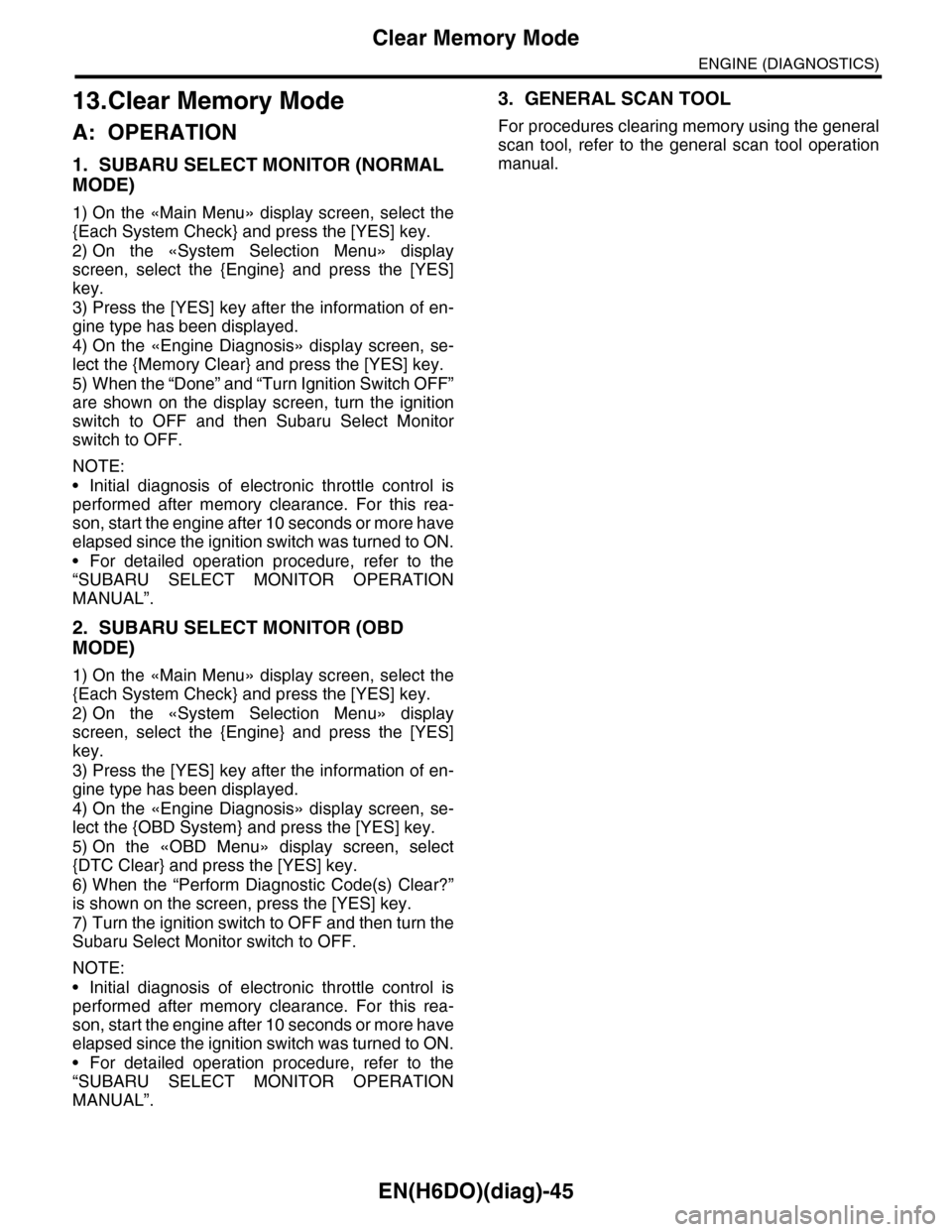
1. SUBARU SELECT MONITOR (NORMAL
MODE)
1) On the «Main Menu» display screen, select the
{Each System Check} and press the [YES] key.
2) On the «System Selection Menu» display
screen, select the {Engine} and press the [YES]
key.
3) Press the [YES] key after the information of en-
gine type has been displayed.
4) On the «Engine Diagnosis» display screen, se-
lect the {Memory Clear} and press the [YES] key.
5) When the “Done” and “Turn Ignition Switch OFF”
are shown on the display screen, turn the ignition
switch to OFF and then Subaru Select Monitor
switch to OFF.
NOTE:
•Initial diagnosis of electronic throttle control is
performed after memory clearance. For this rea-
son, start the engine after 10 seconds or more have
elapsed since the ignition switch was turned to ON.
•For detailed operation procedure, refer to the
“SUBARU SELECT MONITOR OPERATION
MANUAL”.
2. SUBARU SELECT MONITOR (OBD
MODE)
1) On the «Main Menu» display screen, select the
{Each System Check} and press the [YES] key.
2) On the «System Selection Menu» display
screen, select the {Engine} and press the [YES]
key.
3) Press the [YES] key after the information of en-
gine type has been displayed.
4) On the «Engine Diagnosis» display screen, se-
lect the {OBD System} and press the [YES] key.
5) On the «OBD Menu» display screen, select
{DTC Clear} and press the [YES] key.
6) When the “Perform Diagnostic Code(s) Clear?”
is shown on the screen, press the [YES] key.
7) Turn the ignition switch to OFF and then turn the
Subaru Select Monitor switch to OFF.
NOTE:
•Initial diagnosis of electronic throttle control is
performed after memory clearance. For this rea-
son, start the engine after 10 seconds or more have
elapsed since the ignition switch was turned to ON.
•For detailed operation procedure, refer to the
“SUBARU SELECT MONITOR OPERATION
MANUAL”.
3. GENERAL SCAN TOOL
For procedures clearing memory using the general
scan tool, refer to the general scan tool operation
manual.
Page 1207 of 2453
EN(H6DO)(diag)-46
Compulsory Valve Operation Check Mode
ENGINE (DIAGNOSTICS)
14.Compulsory Valve Operation
Check Mode
A: OPERATION
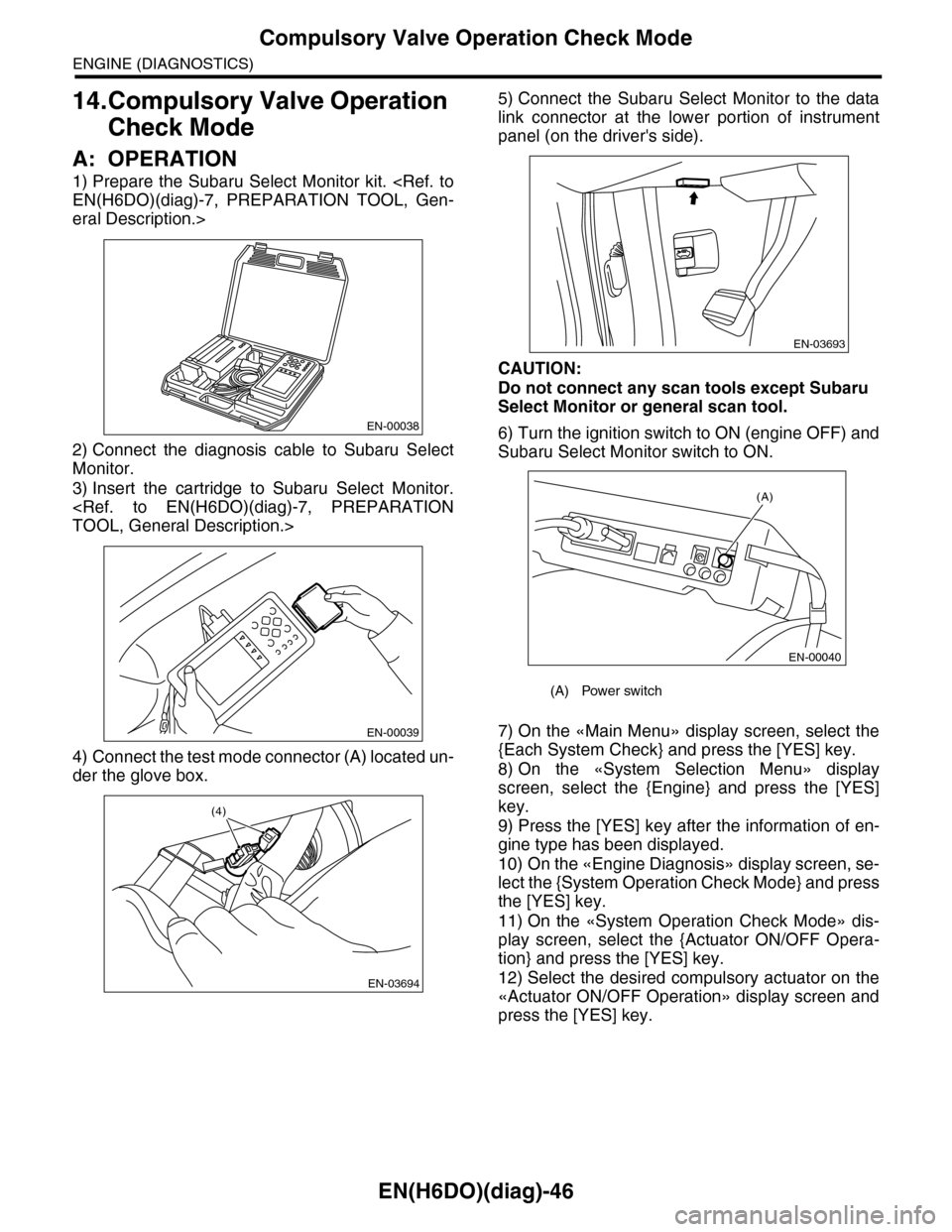
1) Prepare the Subaru Select Monitor kit.
eral Description.>
2) Connect the diagnosis cable to Subaru Select
Monitor.
3) Insert the cartridge to Subaru Select Monitor.
4) Connect the test mode connector (A) located un-
der the glove box.
5) Connect the Subaru Select Monitor to the data
link connector at the lower portion of instrument
panel (on the driver's side).
CAUTION:
Do not connect any scan tools except Subaru
Select Monitor or general scan tool.
6) Turn the ignition switch to ON (engine OFF) and
Subaru Select Monitor switch to ON.
7) On the «Main Menu» display screen, select the
{Each System Check} and press the [YES] key.
8) On the «System Selection Menu» display
screen, select the {Engine} and press the [YES]
key.
9) Press the [YES] key after the information of en-
gine type has been displayed.
10) On the «Engine Diagnosis» display screen, se-
lect the {System Operation Check Mode} and press
the [YES] key.
11) On the «System Operation Check Mode» dis-
play screen, select the {Actuator ON/OFF Opera-
tion} and press the [YES] key.
12) Select the desired compulsory actuator on the
«Actuator ON/OFF Operation» display screen and
press the [YES] key.
EN-00038
EN-00039
EN-03694
(4)
(A) Power switch
EN-03693
(A)
EN-00040
Page 1208 of 2453
![SUBARU TRIBECA 2009 1.G Service Workshop Manual EN(H6DO)(diag)-47
Compulsory Valve Operation Check Mode
ENGINE (DIAGNOSTICS)
13) Pressing the [NO] key completes the compul-
sory valve operation check mode. The display will
then return to SUBARU TRIBECA 2009 1.G Service Workshop Manual EN(H6DO)(diag)-47
Compulsory Valve Operation Check Mode
ENGINE (DIAGNOSTICS)
13) Pressing the [NO] key completes the compul-
sory valve operation check mode. The display will
then return to](/manual-img/17/7322/w960_7322-1207.png)
EN(H6DO)(diag)-47
Compulsory Valve Operation Check Mode
ENGINE (DIAGNOSTICS)
13) Pressing the [NO] key completes the compul-
sory valve operation check mode. The display will
then return to the «Actuator ON/OFF Operation»
screen.
•A list of the support data is shown in the following
table.
NOTE:
•The following parts will be displayed but not
functional.
•For detailed operation procedure, refer to the
“SUBARU SELECT MONITOR OPERATION
MANUAL”.
Description Display
Compulsory fuel pump relay oper-
ation checkFuel Pump
Compulsory radiator fan relay
operation checkRadiator Fan Relay
Compulsory air conditioning relay
operation checkA/C Compressor Relay
Compulsory purge control sole-
noid valve operation checkCPC Solenoid
Compulsory drain valve operation
checkVe n t C o n t r o l S o l e n o i d
Display
EGR Solenoid
ASV Solenoid
FICD Solenoid
Pressure Switching Solenoid 1
Pressure Switching Solenoid 2
Wa st e g at e Con t r ol S ol e no i d
AAI Solenoid
Exhaust Bypass Valve Control Permit Flag
PCV Solenoid
Fuel tank sensor control valve
Page 1210 of 2453
EN(H6DO)(diag)-49
Malfunction Indicator Light
ENGINE (DIAGNOSTICS)
B: ACTIVATION OF MALFUNCTION
INDICATOR LIGHT
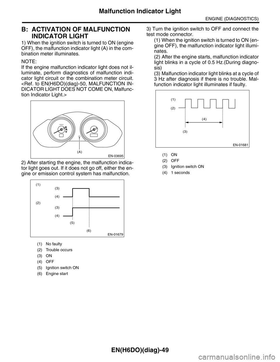
1) When the ignition switch is turned to ON (engine
OFF), the malfunction indicator light (A) in the com-
bination meter illuminates.
NOTE:
If the engine malfunction indicator light does not il-
luminate, perform diagnostics of malfunction indi-
cator light circuit or the combination meter circuit.
tion Indicator Light.>
2) After starting the engine, the malfunction indica-
tor light goes out. If it does not go off, either the en-
gine or emission control system has malfunction.
3) Turn the ignition switch to OFF and connect the
test mode connector.
(1) When the ignition switch is turned to ON (en-
gine OFF), the malfunction indicator light illumi-
nates.
(2) After the engine starts, malfunction indicator
light blinks in a cycle of 0.5 Hz.(During diagno-
sis)
(3) Malfunction indicator light blinks at a cycle of
3 Hz after diagnosis if there is no trouble. Mal-
function indicator light illuminates if faulty.
(1) No faulty
(2) Trouble occurs
(3) ON
(4) OFF
(5) Ignition switch ON
(6) Engine start
EN-03695
CHECKENGINE
(A)
x1000/min
EN-01679
(1)
(2)
(5)
(6)
(3)
(4)
(3)
(4)
(1) ON
(2) OFF
(3) Ignition switch ON
(4) 1 seconds
EN-01681
(2)
(1)
(4)
(3)