Page 2251 of 2453
5AT(diag)-134
General Diagnostic Table
AUTOMATIC TRANSMISSION (DIAGNOSTICS)
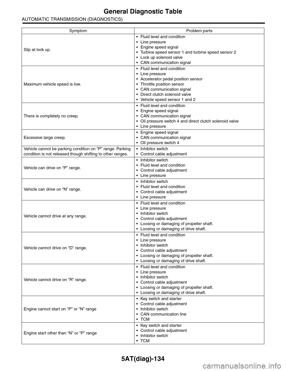
Slip at lock up.
•Fluid level and condition
•Line pressure
•Engine speed signal
•Turbine speed sensor 1 and turbine speed sensor 2
•Lock up solenoid valve
•CAN communication signal
Maximum vehicle speed is low.
•Fluid level and condition
•Line pressure
•Accelerator pedal position sensor
•Throttle position sensor
•CAN communication signal
•Direct clutch solenoid valve
•Vehicle speed sensor 1 and 2
There is completely no creep.
•Fluid level and condition
•Engine speed signal
•CAN communication signal
•Oil pressure switch 4 and direct clutch solenoid valve
•Line pressure
Excessive large creep.
•Engine speed signal
•CAN communication signal
•Oil pressure switch 4
Ve h i c l e c a n n o t b e p a r k i n g c o n d i t i o n o n “ P ” r a n g e . Pa r k i n g
condition is not released though shifting to other ranges.
•Inhibitor switch
•Control cable adjustment
Ve h i c l e c a n d r i v e o n “ P ” r a n g e .
•Inhibitor switch
•Fluid level and condition
•Control cable adjustment
•Line pressure
Ve h i c l e c a n d r i v e o n “ N ” r a n g e .
•Inhibitor switch
•Fluid level and condition
•Control cable adjustment
•Line pressure
Ve h i c l e c a n n o t d r i v e a t a n y r a n g e .
•Fluid level and condition
•Line pressure
•Inhibitor switch
•Control cable adjustment
•Loosing or damaging of propeller shaft.
•Loosing or damaging of drive shaft.
Ve h i c l e c a n n o t d r i v e o n “ D ” r a n g e .
•Fluid level and condition
•Line pressure
•Inhibitor switch
•Control cable adjustment
•Loosing or damaging of propeller shaft.
•Loosing or damaging of drive shaft.
Ve h i c l e c a n n o t d r i v e o n “ R ” r a n g e .
•Fluid level and condition
•Line pressure
•Inhibitor switch
•Control cable adjustment
•Loosing or damaging of propeller shaft.
•Loosing or damaging of drive shaft.
Engine cannot start on “P” or “N” range
•Key switch and starter
•Control cable adjustment
•Inhibitor switch
•CAN communication line
•TCM
Engine start other than “N” or “P” range
•Key switch and starter
•Control cable adjustment
•Inhibitor switch
•TCM
Symptom Problem parts
Page 2257 of 2453
CS-5
AT Shift Lock Control System
CONTROL SYSTEMS
2. AT Shift Lock Control System
A: LOCATION
(1) TCM (“P” range) (4) Key cylinder (with built-in key
warning switch)
(6) “P” range switch
(2) Body integrated unit (7) Key lock solenoid
(3) Stop light switch (5) Shift lock solenoid ASSY
CS-00595
(4)
(6)
(5)
(7)(1)
(2)
(3)
Page 2259 of 2453
CS-7
AT Shift Lock Control System
CONTROL SYSTEMS
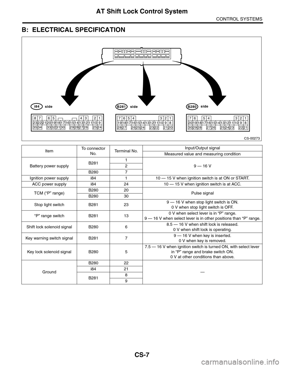
B: ELECTRICAL SPECIFICATION
ItemTo c o n n e c t o r
No.Te r m i n a l N o .Input/Output signal
Measured value and measuring condition
Battery power supplyB2811
9 — 16 V2
B280 7
Ignition power supply i84 1 10 — 15 V when ignition switch is at ON or START.
ACC power supply i84 24 10 — 15 V when ignition switch is at ACC.
TCM (“P” range)B280 20Pulse signalB280 30
Stop light switch B281 239 — 16 V when stop light switch is ON.
0 V when stop light switch is OFF.
“P” range switch B281 130 V when select lever is in “P” range.
9 — 16 V when select lever is in other positions than “P” range.
Shift lock solenoid signal B280 68.5 — 16 V when shift lock is released.
0 V when shift lock is operating.
Key war ning switch signal B281 79 — 16 V when key is inserted.
0 V when key is removed.
Key lock solenoid signal B280 5
7.5 — 16 V when ignition switch is turned ON, with select lever
in “P” range and brake switch ON.
0 V at other conditions than above.
Ground
B280 22
—i84 21
B2818
9
CS-00273
71928
61827
51741626152514241312231122
3102921
1820
B281side
72030
619291828
51741627152614132512241123
3102922
1821
B280side
82335
722342162033
51932183117301615291428
41327
312261121025
1924
i84side
Page 2260 of 2453
CS-8
AT Shift Lock Control System
CONTROL SYSTEMS
C: WIRING DIAGRAM
(1) Ignition switch (4) Body integrated unit (7) Shift lock solenoid
(2) Stop light switch (5) TCM (“P” range) (8) “P” range switch
(3) Key warning switch (6) Key lock solenoid (9) Battery
CS-00363
OFFACCON
(1)
(2)
(3)
(4)
(9)
(6)
(7)
(8)
(5)
Page 2261 of 2453
CS-9
AT Shift Lock Control System
CONTROL SYSTEMS
D: INSPECTION
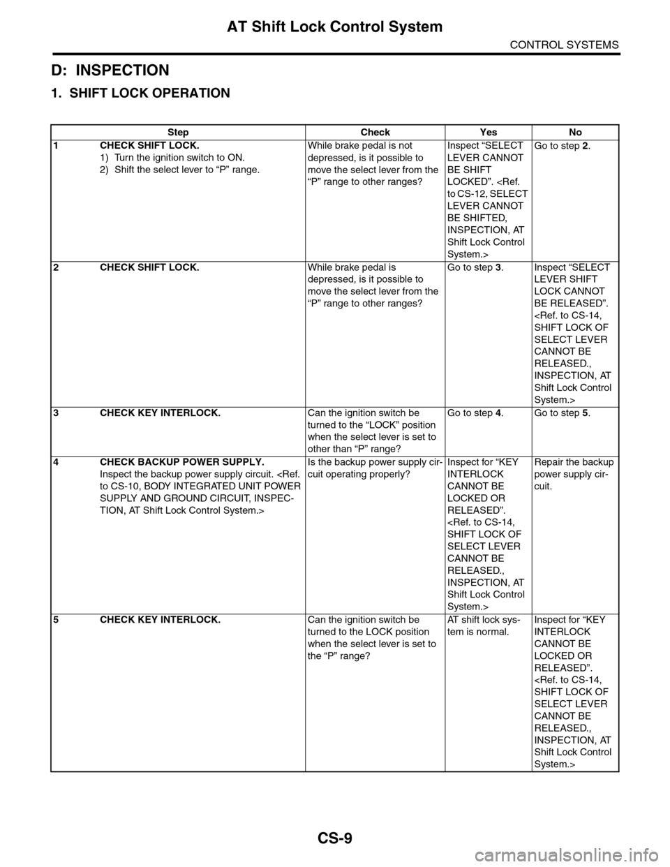
1. SHIFT LOCK OPERATION
Step Check Yes No
1CHECK SHIFT LOCK.
1) Turn the ignition switch to ON.
2) Shift the select lever to “P” range.
While brake pedal is not
depressed, is it possible to
move the select lever from the
“P” range to other ranges?
Inspect “SELECT
LEVER CANNOT
BE SHIFT
LOCKED”.
to CS-12, SELECT
LEVER CANNOT
BE SHIFTED,
INSPECTION, AT
Shift Lock Control
System.>
Go to step 2.
2CHECK SHIFT LOCK.While brake pedal is
depressed, is it possible to
move the select lever from the
“P” range to other ranges?
Go to step 3.Inspect “SELECT
LEVER SHIFT
LOCK CANNOT
BE RELEASED”.
SHIFT LOCK OF
SELECT LEVER
CANNOT BE
RELEASED.,
INSPECTION, AT
Shift Lock Control
System.>
3CHECK KEY INTERLOCK.Can the ignition switch be
turned to the “LOCK” position
when the select lever is set to
other than “P” range?
Go to step 4.Go to step 5.
4CHECK BACKUP POWER SUPPLY.
Inspect the backup power supply circuit.
to CS-10, BODY INTEGRATED UNIT POWER
SUPPLY AND GROUND CIRCUIT, INSPEC-
TION, AT Shift Lock Control System.>
Is the backup power supply cir-
cuit operating properly?
Inspect for “KEY
INTERLOCK
CANNOT BE
LOCKED OR
RELEASED”.
SHIFT LOCK OF
SELECT LEVER
CANNOT BE
RELEASED.,
INSPECTION, AT
Shift Lock Control
System.>
Repair the backup
power supply cir-
cuit.
5CHECK KEY INTERLOCK.Can the ignition switch be
turned to the LOCK position
when the select lever is set to
the “P” range?
AT s h i f t l o c k s y s -
tem is normal.
Inspect for “KEY
INTERLOCK
CANNOT BE
LOCKED OR
RELEASED”.
SHIFT LOCK OF
SELECT LEVER
CANNOT BE
RELEASED.,
INSPECTION, AT
Shift Lock Control
System.>
Page 2268 of 2453
CS-16
AT Shift Lock Control System
CONTROL SYSTEMS
5. KEY INTERLOCK DOES NOT LOCK OR RELEASE
CS-00602
E
B116
5467821931022 231112131415242526 2716171828 29192021 30
B280B:
NO.14
EE
B281C:
B280B:
i84A:
C7B7
B5
12
C13A3
B1162
212
1
2
B350
B350
i3
B38
B420
B410
3
4
BATTERY
KEY WARNING SWITCH
BODY INTEGRATED UNIT
"P"RANGE SWITCH
KEY LOCK SOLENOID
TEST MODECONNECTOR
1234
B350
567821943102422 23 25111213141526 27281617181920 21
B281C:
i84A:
123456789101112
NO.8
MAINSBF
B420
12
B421
12
B38
1234 5678910 11 12 13 16 17 18 19 2014151234567891011121415161718192021222324252627282930313233343513
Page 2269 of 2453
CS-17
AT Shift Lock Control System
CONTROL SYSTEMS
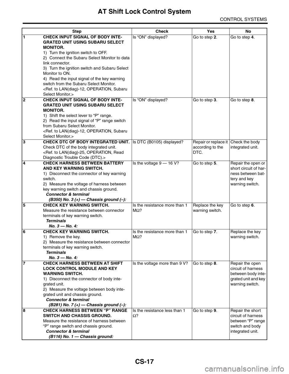
Step Check Yes No
1CHECK INPUT SIGNAL OF BODY INTE-
GRATED UNIT USING SUBARU SELECT
MONITOR.
1) Turn the ignition switch to OFF.
2) Connect the Subaru Select Monitor to data
link connector.
3) Turn the ignition switch and Subaru Select
Monitor to ON.
4) Read the input signal of the key warning
switch from the Subaru Select Monitor.
Select Monitor.>
Is “ON” displayed? Go to step 2.Go to step 4.
2CHECK INPUT SIGNAL OF BODY INTE-
GRATED UNIT USING SUBARU SELECT
MONITOR.
1) Shift the select lever to “P” range.
2) Read the input signal of “P” range switch
from Subaru Select Monitor.
Select Monitor.>
Is “ON” displayed? Go to step 3.Go to step 8.
3CHECK DTC OF BODY INTEGRATED UNIT.
Check DTC of the body integrated unit.
Diagnostic Trouble Code (DTC).>
Is DTC (B0105) displayed? Repair or replace it
according to the
DTC.
Check the body
integrated unit.
4CHECK HARNESS BETWEEN BATTERY
AND KEY WARNING SWITCH.
1) Disconnect the connector of key warning
switch.
2) Measure the voltage of harness between
key warning switch and chassis ground.
Connector & terminal
(B350) No. 3 (+) — Chassis ground (–):
Is the voltage 9 — 16 V? Go to step 5.Repair the open or
short circuit of har-
ness between bat-
tery and key
warning switch.
5 CHECK KEY WARNING SWITCH.
Measure the resistance between connector
terminals of key warning switch.
Te r m i n a l s
No. 3 — No. 4:
Is the resistance more than 1
MΩ?
Replace the key
warning switch.
Go to step 6.
6 CHECK KEY WARNING SWITCH.
1) Remove the key.
2) Measure the resistance between connector
terminals of key warning switch.
Te r m i n a l s
No. 3 — No. 4:
Is the resistance more than 1
MΩ?
Go to step 7.Replace the key
warning switch.
7CHECK HARNESS BETWEEN AT SHIFT
LOCK CONTROL MODULE AND KEY
WARNING SWITCH.
1) Disconnect the connector of body inte-
grated unit.
2) Measure the voltage between body inte-
grated unit and chassis ground.
Connector & terminal
(B281) No. 7 (+) — Chassis ground (–):
Is the voltage more than 9 V? Go to step 8.Repair the open
circuit of harness
between body inte-
grated unit and key
warning switch.
8CHECK HARNESS BETWEEN “P” RANGE
SWITCH AND CHASSIS GROUND.
Measure the resistance of harness between
“P” range switch and chassis ground.
Connector & terminal
(B116) No. 1 — Chassis ground:
Is the resistance less than 1
Ω?
Go to step 9.Repair the short
circuit of harness
between “P” range
switch and body
integrated unit.
Page 2270 of 2453
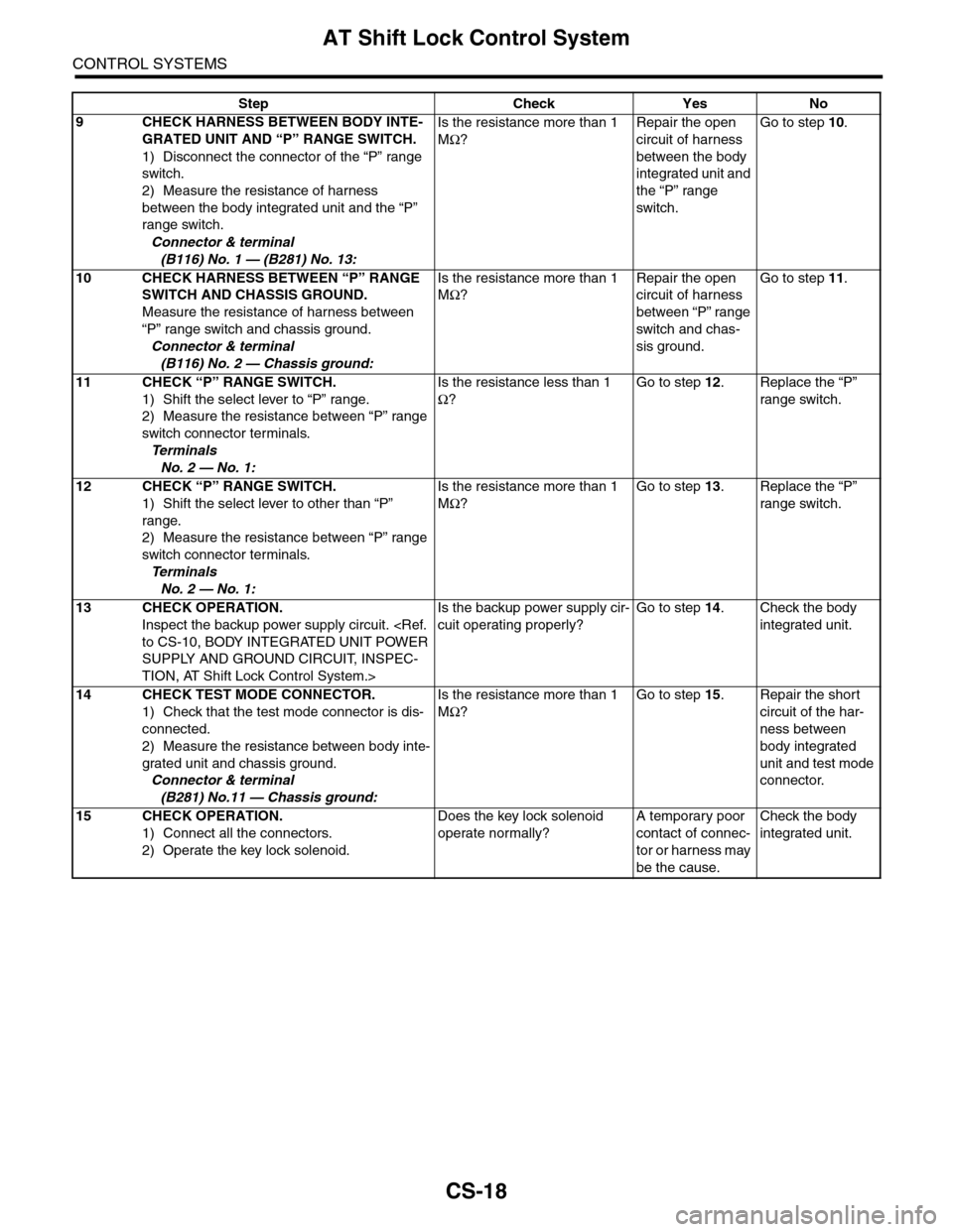
CS-18
AT Shift Lock Control System
CONTROL SYSTEMS
9CHECK HARNESS BETWEEN BODY INTE-
GRATED UNIT AND “P” RANGE SWITCH.
1) Disconnect the connector of the “P” range
switch.
2) Measure the resistance of harness
between the body integrated unit and the “P”
range switch.
Connector & terminal
(B116) No. 1 — (B281) No. 13:
Is the resistance more than 1
MΩ?
Repair the open
circuit of harness
between the body
integrated unit and
the “P” range
switch.
Go to step 10.
10 CHECK HARNESS BETWEEN “P” RANGE
SWITCH AND CHASSIS GROUND.
Measure the resistance of harness between
“P” range switch and chassis ground.
Connector & terminal
(B116) No. 2 — Chassis ground:
Is the resistance more than 1
MΩ?
Repair the open
circuit of harness
between “P” range
switch and chas-
sis ground.
Go to step 11.
11 CHECK “P” RANGE SWITCH.
1) Shift the select lever to “P” range.
2) Measure the resistance between “P” range
switch connector terminals.
Te r m i n a l s
No. 2 — No. 1:
Is the resistance less than 1
Ω?
Go to step 12.Replace the “P”
range switch.
12 CHECK “P” RANGE SWITCH.
1) Shift the select lever to other than “P”
range.
2) Measure the resistance between “P” range
switch connector terminals.
Te r m i n a l s
No. 2 — No. 1:
Is the resistance more than 1
MΩ?
Go to step 13.Replace the “P”
range switch.
13 CHECK OPERATION.
Inspect the backup power supply circuit.
to CS-10, BODY INTEGRATED UNIT POWER
SUPPLY AND GROUND CIRCUIT, INSPEC-
TION, AT Shift Lock Control System.>
Is the backup power supply cir-
cuit operating properly?
Go to step 14.Check the body
integrated unit.
14 CHECK TEST MODE CONNECTOR.
1) Check that the test mode connector is dis-
connected.
2) Measure the resistance between body inte-
grated unit and chassis ground.
Connector & terminal
(B281) No.11 — Chassis ground:
Is the resistance more than 1
MΩ?
Go to step 15.Repair the short
circuit of the har-
ness between
body integrated
unit and test mode
connector.
15 CHECK OPERATION.
1) Connect all the connectors.
2) Operate the key lock solenoid.
Does the key lock solenoid
operate normally?
A temporary poor
contact of connec-
tor or harness may
be the cause.
Check the body
integrated unit.
Step Check Yes No