Page 1876 of 2453
ME(H6DO)-10
General Description
MECHANICAL
5. CYLINDER HEAD AND VALVE ASSEMBLY
(1) Exhaust valve (7) Valve spring (Outer) (13) Exhaust valve stem seal
(2) Intake valve (8) Retainer (14) Valve spring
(3) Intake valve guide (9) Retainer key (15) Valve lifter (Exhaust)
(4) Valve spring seat (10) Shim (16) Cylinder head plug
(5) Intake valve stem seal (11) Valve lifter (Intake) (17) Cylinder head
(6) Valve spring (Inner) (12) Exhaust valve guide
ME-02024
(16)
(16)
(17)
(3)
(12)
(13)
(4)
(14)
(8)
(9)
(15)
(4) (5) (6)(7)(8)(9)(11)(10)
(1)
(2)
Page 1879 of 2453
ME(H6DO)-13
General Description
MECHANICAL
7. CRANKSHAFT AND PISTON
(1) Reinforcement (9) Piston pin (16) Crankshaft bearing #1, #3, #5
(2) Drive plate (10) Connecting rod (17) Crankshaft bearing #2, #4, #6
(3) Crankshaft sensor plate (11) Connecting rod bearing (18) Crankshaft bearing #7
(4) Top ring (12) Connecting rod bolt
(5) Second ring (13) Connecting rod capTightening torque: N·m (kgf-m, ft-lb)
(6) Oil ring (14) CrankshaftT1: 53 (5.4, 39)
(7) Snap ring (15) Woodruff keyT2: 81 (8.3, 60)
(8) Piston
(9)(1)
(3)
(2)
(4)
(5)
(6)
(7)(8)
(9)
(7)
(8)
(7)
(6)
(5)
(4)
(7)
(15)
(11)
(13)
(12)
(12)
(14)
(10)
(11)
(11)(13)
(18)
(16)(17)
(17)(16)(17)(16)
(10)
T1
T2
T1
ME-02454
Page 1911 of 2453
ME(H6DO)-45
Timing Chain Assembly
MECHANICAL
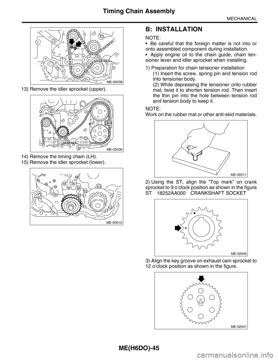
13) Remove the idler sprocket (upper).
14) Remove the timing chain (LH).
15) Remove the idler sprocket (lower).
B: INSTALLATION
NOTE:
•Be careful that the foreign matter is not into or
onto assembled component during installation.
•Apply engine oil to the chain guide, chain ten-
sioner lever and idler sprocket when installing.
1) Preparation for chain tensioner installation
(1) Insert the screw, spring pin and tension rod
into tensioner body.
(2) While depressing the tensioner onto rubber
mat, twist it to shorten tension rod. Then insert
the thin pin into the hole between tension rod
and tension body to keep it.
NOTE:
Work on the rubber mat or other anti-skid materials.
2) Using the ST, align the “Top mark” on crank
sprocket to 9 o’clock position as shown in the figure
ST 18252AA000 CRANKSHAFT SOCKET
3) Align the key groove on exhaust cam sprocket to
12 o’clock position as shown in the figure.
ME-02038
ME-02039
ME-00510
ME-00511
ME-02040
ME-02041
Page 1915 of 2453
ME(H6DO)-49
Cam Sprocket
MECHANICAL
16.Cam Sprocket
A: REMOVAL
1) Remove the crank pulley.
41, REMOVAL, Crank Pulley.>
2) Remove the front chain cover.
ME(H6DO)-42, REMOVAL, Front Chain Cover.>
3) Remove the timing chain assembly.
Assembly.>
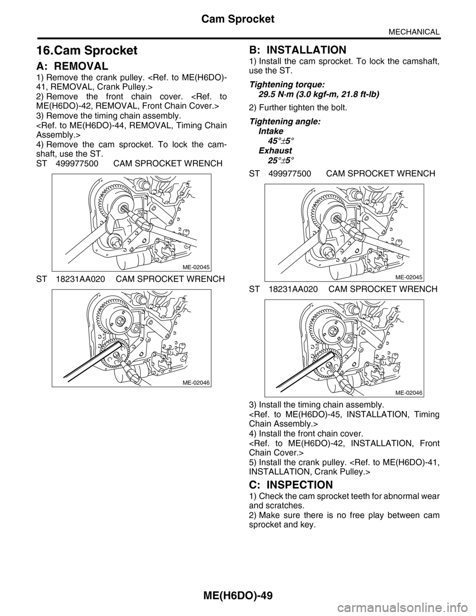
4) Remove the cam sprocket. To lock the cam-
shaft, use the ST.
ST 499977500 CAM SPROCKET WRENCH
ST 18231AA020 CAM SPROCKET WRENCH
B: INSTALLATION
1) Install the cam sprocket. To lock the camshaft,
use the ST.
Tightening torque:
29.5 N·m (3.0 kgf-m, 21.8 ft-lb)
2) Further tighten the bolt.
Tightening angle:
Intake
45°±5°
Exhaust
25°±5°
ST 499977500 CAM SPROCKET WRENCH
ST 18231AA020 CAM SPROCKET WRENCH
3) Install the timing chain assembly.
Chain Assembly.>
4) Install the front chain cover.
Chain Cover.>
5) Install the crank pulley.
INSTALLATION, Crank Pulley.>
C: INSPECTION
1) Check the cam sprocket teeth for abnormal wear
and scratches.
2) Make sure there is no free play between cam
sprocket and key.
ME-02045
ME-02046
ME-02045
ME-02046
Page 1916 of 2453
ME(H6DO)-50
Crank Sprocket
MECHANICAL
17.Crank Sprocket
A: REMOVAL
1) Remove the crank pulley.
41, REMOVAL, Crank Pulley.>
2) Remove the front chain cover.
ME(H6DO)-42, REMOVAL, Front Chain Cover.>
3) Remove the timing chain assembly.
Assembly.>
4) Remove the crank sprocket (A).
B: INSTALLATION
1) Install the crank sprocket (A).
2) Install the timing chain assembly.
Chain Assembly.>
3) Install the front chain cover.
Chain Cover.>
4) Install the crank pulley.
INSTALLATION, Crank Pulley.>
C: INSPECTION
1) Check the crank sprocket teeth for abnormal
wear and scratches.
2) Make sure there is no free play between crank
sprocket and key.
ME-02047
(A)
ME-02047
(A)
Page 1924 of 2453
ME(H6DO)-58
Cylinder Head
MECHANICAL
8) Install the front chain cover.
Chain Cover.>
9) Install the crank pulley.
Pulley.>
C: DISASSEMBLY
1) Set the cylinder head on ST.
ST 18250AA010 CYLINDER HEAD TABLE
2) Remove the valve lifter.
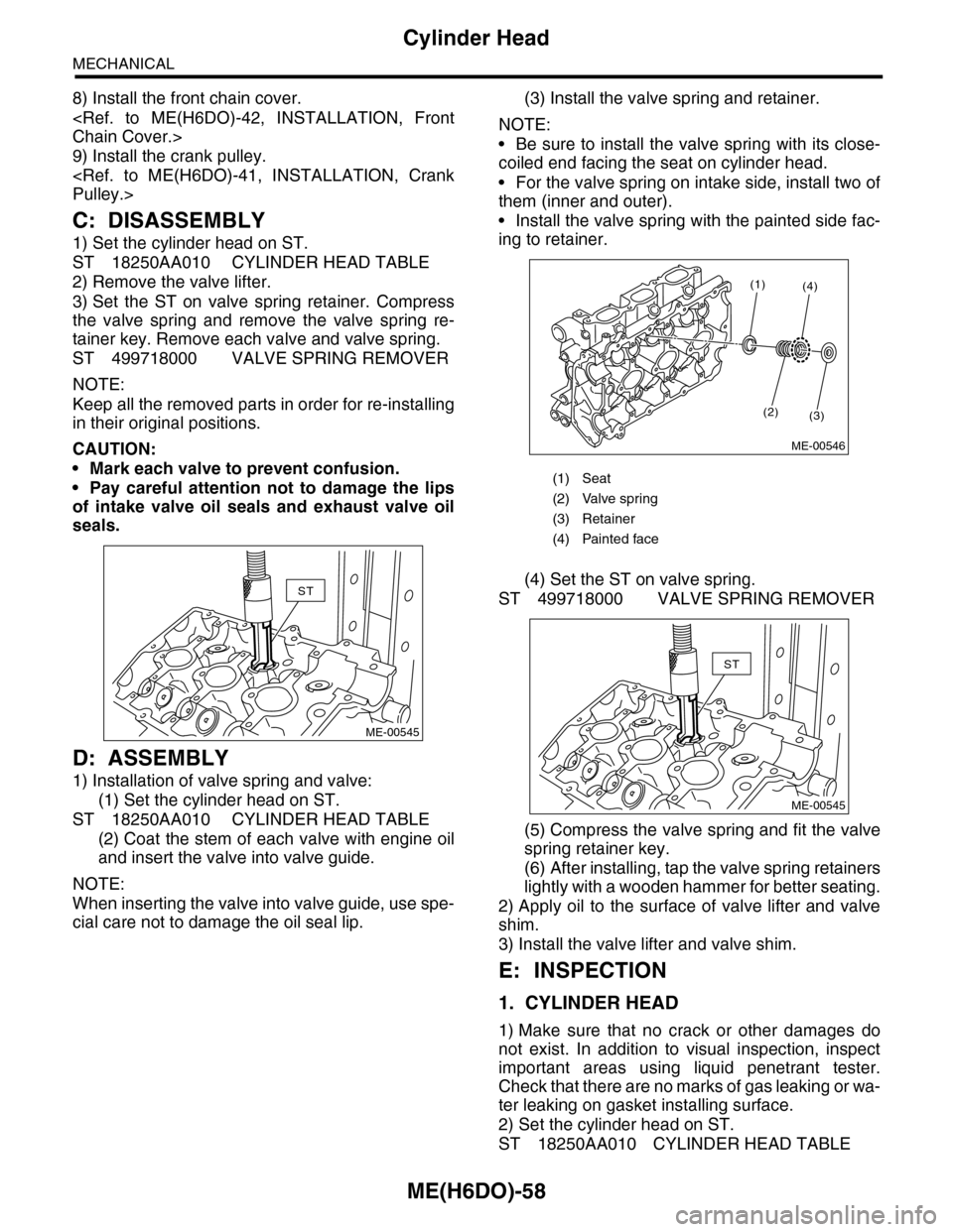
3) Set the ST on valve spring retainer. Compress
the valve spring and remove the valve spring re-
tainer key. Remove each valve and valve spring.
ST 499718000 VALVE SPRING REMOVER
NOTE:
Keep all the removed parts in order for re-installing
in their original positions.
CAUTION:
•Mark each valve to prevent confusion.
•Pay careful attention not to damage the lips
of intake valve oil seals and exhaust valve oil
seals.
D: ASSEMBLY
1) Installation of valve spring and valve:
(1) Set the cylinder head on ST.
ST 18250AA010 CYLINDER HEAD TABLE
(2) Coat the stem of each valve with engine oil
and insert the valve into valve guide.
NOTE:
When inserting the valve into valve guide, use spe-
cial care not to damage the oil seal lip.
(3) Install the valve spring and retainer.
NOTE:
•Be sure to install the valve spring with its close-
coiled end facing the seat on cylinder head.
•For the valve spring on intake side, install two of
them (inner and outer).
•Install the valve spring with the painted side fac-
ing to retainer.
(4) Set the ST on valve spring.
ST 499718000 VALVE SPRING REMOVER
(5) Compress the valve spring and fit the valve
spring retainer key.
(6) After installing, tap the valve spring retainers
lightly with a wooden hammer for better seating.
2) Apply oil to the surface of valve lifter and valve
shim.
3) Install the valve lifter and valve shim.
E: INSPECTION
1. CYLINDER HEAD
1) Make sure that no crack or other damages do
not exist. In addition to visual inspection, inspect
important areas using liquid penetrant tester.
Check that there are no marks of gas leaking or wa-
ter leaking on gasket installing surface.
2) Set the cylinder head on ST.
ST 18250AA010 CYLINDER HEAD TABLE
ST
ME-00545
(1) Seat
(2) Valve spring
(3) Retainer
(4) Painted face
(1)
(2)(3)
(4)
ME-00546
ST
ME-00545
Page 2132 of 2453
5AT(diag)-15
Subaru Select Monitor
AUTOMATIC TRANSMISSION (DIAGNOSTICS)
6. Subaru Select Monitor
A: OPERATION
1. READ DIAGNOSTIC TROUBLE CODE
(DTC)
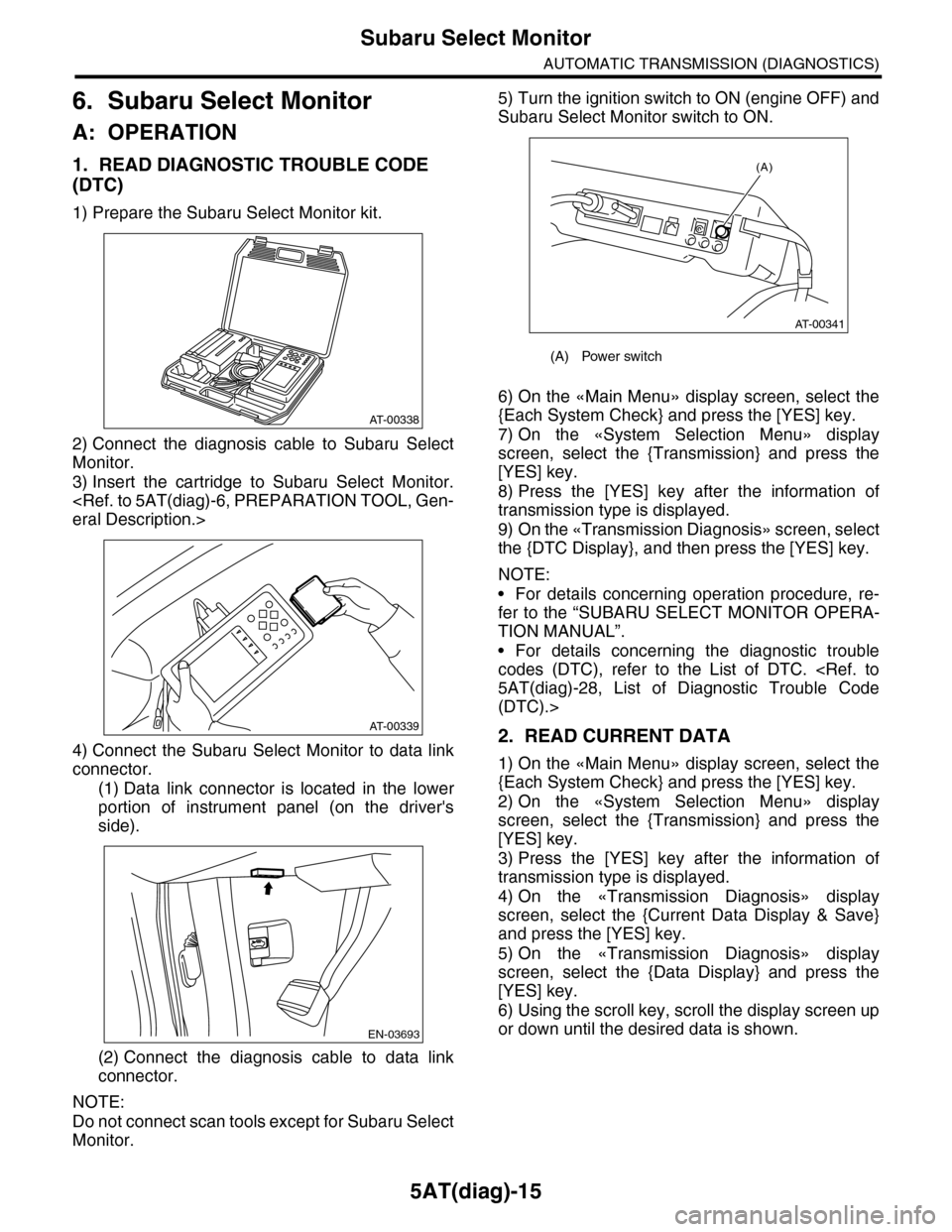
1) Prepare the Subaru Select Monitor kit.
2) Connect the diagnosis cable to Subaru Select
Monitor.
3) Insert the cartridge to Subaru Select Monitor.
eral Description.>
4) Connect the Subaru Select Monitor to data link
connector.
(1) Data link connector is located in the lower
portion of instrument panel (on the driver's
side).
(2) Connect the diagnosis cable to data link
connector.
NOTE:
Do not connect scan tools except for Subaru Select
Monitor.
5) Turn the ignition switch to ON (engine OFF) and
Subaru Select Monitor switch to ON.
6) On the «Main Menu» display screen, select the
{Each System Check} and press the [YES] key.
7) On the «System Selection Menu» display
screen, select the {Transmission} and press the
[YES] key.
8) Press the [YES] key after the information of
transmission type is displayed.
9) On the «Transmission Diagnosis» screen, select
the {DTC Display}, and then press the [YES] key.
NOTE:
•For details concerning operation procedure, re-
fer to the “SUBARU SELECT MONITOR OPERA-
TION MANUAL”.
•For details concerning the diagnostic trouble
codes (DTC), refer to the List of DTC.
5AT(diag)-28, List of Diagnostic Trouble Code
(DTC).>
2. READ CURRENT DATA
1) On the «Main Menu» display screen, select the
{Each System Check} and press the [YES] key.
2) On the «System Selection Menu» display
screen, select the {Transmission} and press the
[YES] key.
3) Press the [YES] key after the information of
transmission type is displayed.
4) On the «Transmission Diagnosis» display
screen, select the {Current Data Display & Save}
and press the [YES] key.
5) On the «Transmission Diagnosis» display
screen, select the {Data Display} and press the
[YES] key.
6) Using the scroll key, scroll the display screen up
or down until the desired data is shown.
AT-00338
AT-00339
EN-03693
(A) Power switch
(A)
AT-00341
Page 2134 of 2453
5AT(diag)-17
Subaru Select Monitor
AUTOMATIC TRANSMISSION (DIAGNOSTICS)
3. CLEAR MEMORY MODE
NOTE:
To clear the previous DTC, use {Clear Memory},
and to clear the learned value, use {Clear Memory
2}.
1) Check that the select lever is in “P” range.
2) On the «Main Menu» display screen, select the
{Each System Check} and press the [YES] key.
3) On the «System Selection Menu» display
screen, select the {Transmission} and press the
[YES] key.
4) Press the [YES] key after the information of
transmission type is displayed.
5) On the «Transmission Diagnosis» display
screen, select the {Clear Memory} and press the
[YES] key.
NOTE:
If {Clear Memory 2} is selected and performed,
DTC are not cleared.
6) When ‘Done’ is shown on the display screen,
turn off the Subaru Select Monitor and turn the ig-
nition switch to OFF. To turn the ignition switch to
ON again, wait for more than 10 seconds.
NOTE:
For details concerning operation procedure, refer
to the “SUBARU SELECT MONITOR OPERATION
MANUAL”.