2009 SUBARU TRIBECA key
[x] Cancel search: keyPage 1207 of 2453
EN(H6DO)(diag)-46
Compulsory Valve Operation Check Mode
ENGINE (DIAGNOSTICS)
14.Compulsory Valve Operation
Check Mode
A: OPERATION
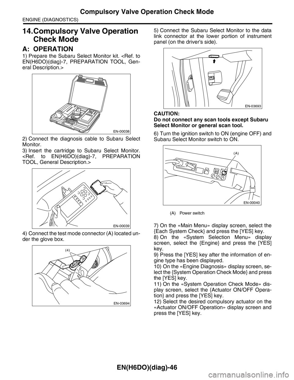
1) Prepare the Subaru Select Monitor kit.
eral Description.>
2) Connect the diagnosis cable to Subaru Select
Monitor.
3) Insert the cartridge to Subaru Select Monitor.
4) Connect the test mode connector (A) located un-
der the glove box.
5) Connect the Subaru Select Monitor to the data
link connector at the lower portion of instrument
panel (on the driver's side).
CAUTION:
Do not connect any scan tools except Subaru
Select Monitor or general scan tool.
6) Turn the ignition switch to ON (engine OFF) and
Subaru Select Monitor switch to ON.
7) On the «Main Menu» display screen, select the
{Each System Check} and press the [YES] key.
8) On the «System Selection Menu» display
screen, select the {Engine} and press the [YES]
key.
9) Press the [YES] key after the information of en-
gine type has been displayed.
10) On the «Engine Diagnosis» display screen, se-
lect the {System Operation Check Mode} and press
the [YES] key.
11) On the «System Operation Check Mode» dis-
play screen, select the {Actuator ON/OFF Opera-
tion} and press the [YES] key.
12) Select the desired compulsory actuator on the
«Actuator ON/OFF Operation» display screen and
press the [YES] key.
EN-00038
EN-00039
EN-03694
(4)
(A) Power switch
EN-03693
(A)
EN-00040
Page 1208 of 2453
![SUBARU TRIBECA 2009 1.G Service Workshop Manual EN(H6DO)(diag)-47
Compulsory Valve Operation Check Mode
ENGINE (DIAGNOSTICS)
13) Pressing the [NO] key completes the compul-
sory valve operation check mode. The display will
then return to SUBARU TRIBECA 2009 1.G Service Workshop Manual EN(H6DO)(diag)-47
Compulsory Valve Operation Check Mode
ENGINE (DIAGNOSTICS)
13) Pressing the [NO] key completes the compul-
sory valve operation check mode. The display will
then return to](/manual-img/17/7322/w960_7322-1207.png)
EN(H6DO)(diag)-47
Compulsory Valve Operation Check Mode
ENGINE (DIAGNOSTICS)
13) Pressing the [NO] key completes the compul-
sory valve operation check mode. The display will
then return to the «Actuator ON/OFF Operation»
screen.
•A list of the support data is shown in the following
table.
NOTE:
•The following parts will be displayed but not
functional.
•For detailed operation procedure, refer to the
“SUBARU SELECT MONITOR OPERATION
MANUAL”.
Description Display
Compulsory fuel pump relay oper-
ation checkFuel Pump
Compulsory radiator fan relay
operation checkRadiator Fan Relay
Compulsory air conditioning relay
operation checkA/C Compressor Relay
Compulsory purge control sole-
noid valve operation checkCPC Solenoid
Compulsory drain valve operation
checkVe n t C o n t r o l S o l e n o i d
Display
EGR Solenoid
ASV Solenoid
FICD Solenoid
Pressure Switching Solenoid 1
Pressure Switching Solenoid 2
Wa st e g at e Con t r ol S ol e no i d
AAI Solenoid
Exhaust Bypass Valve Control Permit Flag
PCV Solenoid
Fuel tank sensor control valve
Page 1235 of 2453
EN(H6DO)(diag)-74
List of Diagnostic Trouble Code (DTC)
ENGINE (DIAGNOSTICS)
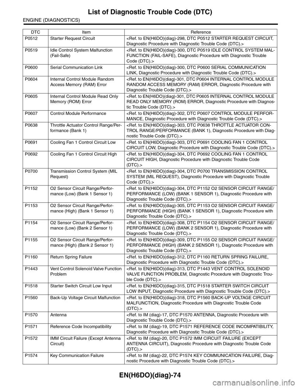
P0512 Starter Request Circuit
P0519 Idle Control System Malfunction
(Fail-Safe)
Code (DTC).>
P0600 Serial Communication Link
P0604 Internal Control Module Random
Access Memory (RAM) Error
Diagnostic Trouble Code (DTC).>
P0605 Internal Control Module Read Only
Memory (ROM) Error
tic Trouble Code (DTC).>
P0607 Control Module Performance
P0638 Throttle Actuator Control Range/Per-
for mance (Bank 1)
nostic Trouble Code (DTC).>
P0691 Cooling Fan 1 Control Circuit Low
P0692 Cooling Fan 1 Control Circuit High
(DTC).>
P0700 Transmission Control System (MIL
Request)
Code (DTC).>
P1152 O2 Sensor Circuit Range/Perfor-
mance (Low) (Bank 1 Sensor 1)
Diagnostic Trouble Code (DTC).>
P1153 O2 Sensor Circuit Range/Perfor-
mance (High) (Bank 1 Sensor 1)
Diagnostic Trouble Code (DTC).>
P1154 O2 Sensor Circuit Range/Perfor-
mance (Low) (Bank 2 Sensor 1)
Diagnostic Trouble Code (DTC).>
P1155 O2 Sensor Circuit Range/Perfor-
mance (High) (Bank 2 Sensor 1)
Diagnostic Trouble Code (DTC).>
P1160 Return Spring Failure
P1443 Vent Control Solenoid Valve Function
Problem
ble Code (DTC).>
P1518 Starter Switch Circuit Low Input
P1560 Back-Up Voltage Circuit Malfunction
(DTC).>
P1570 Antenna
P1571 Reference Code Incompatibility
P1572 IMM Circuit Failure (Except Antenna
Circuit)
(DTC).>
P1574 Key Communication Failure
DTC Item Reference
Page 1593 of 2453
FU(H6DO)-32
Engine Control Module (ECM)
FUEL INJECTION (FUEL SYSTEMS)
16.Engine Control Module (ECM)
A: REMOVAL
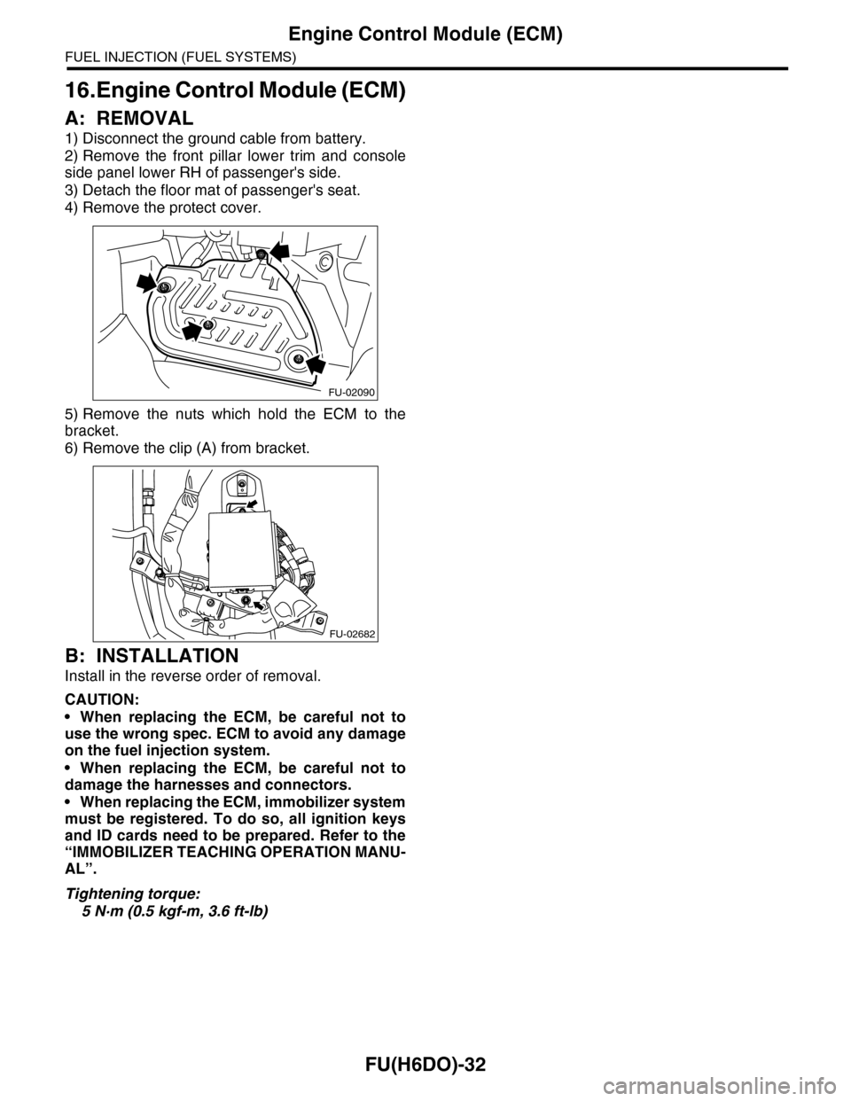
1) Disconnect the ground cable from battery.
2) Remove the front pillar lower trim and console
side panel lower RH of passenger's side.
3) Detach the floor mat of passenger's seat.
4) Remove the protect cover.
5) Remove the nuts which hold the ECM to the
bracket.
6) Remove the clip (A) from bracket.
B: INSTALLATION
Install in the reverse order of removal.
CAUTION:
•When replacing the ECM, be careful not to
use the wrong spec. ECM to avoid any damage
on the fuel injection system.
•When replacing the ECM, be careful not to
damage the harnesses and connectors.
•When replacing the ECM, immobilizer system
must be registered. To do so, all ignition keys
and ID cards need to be prepared. Refer to the
“IMMOBILIZER TEACHING OPERATION MANU-
AL”.
Tightening torque:
5 N·m (0.5 kgf-m, 3.6 ft-lb)
FU-02090
FU-02682
Page 1618 of 2453
GD(H6DO)-6
List of Diagnostic Trouble Code (DTC)
GENERAL DESCRIPTION
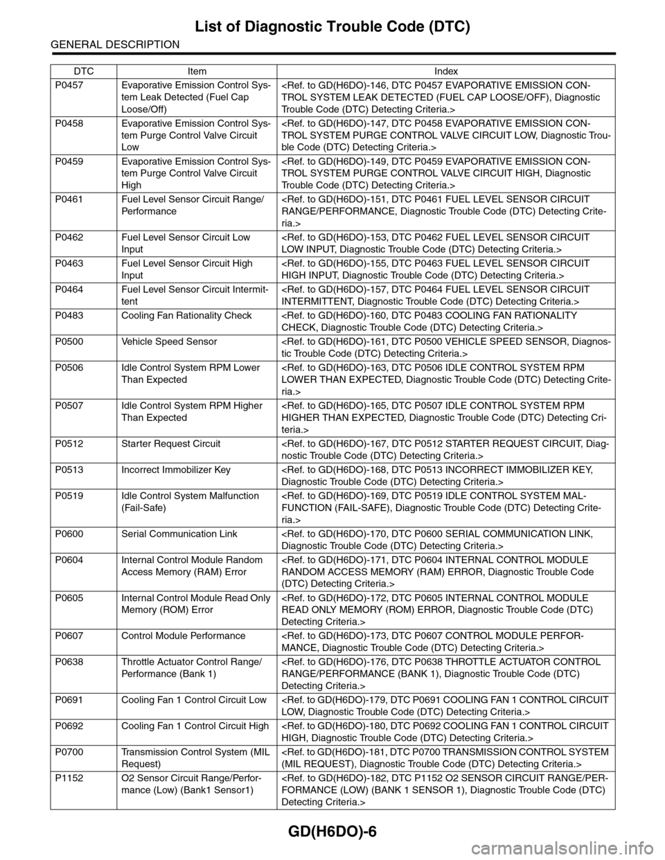
P0457 Evaporative Emission Control Sys-
tem Leak Detected (Fuel Cap
Loose/Off)
Tr o u b l e C o d e ( D T C ) D e t e c t i n g C r i t e r i a . >
P0458 Evaporative Emission Control Sys-
tem Purge Control Valve Circuit
Low
ble Code (DTC) Detecting Criteria.>
P0459 Evaporative Emission Control Sys-
tem Purge Control Valve Circuit
High
Tr o u b l e C o d e ( D T C ) D e t e c t i n g C r i t e r i a . >
P0461 Fuel Level Sensor Circuit Range/
Per fo r m an ce
ria.>
P0462 Fuel Level Sensor Circuit Low
Input
P0463 Fuel Level Sensor Circuit High
Input
P0464 Fuel Level Sensor Circuit Intermit-
tent
P0483 Cooling Fan Rationality Check
P0500 Vehicle Speed Sensor
P0506 Idle Control System RPM Lower
Than Expected
ria.>
P0507 Idle Control System RPM Higher
Than Expected
teria.>
P0512 Starter Request Circuit
P0513 Incorrect Immobilizer Key
P0519 Idle Control System Malfunction
(Fail-Safe)
ria.>
P0600 Serial Communication Link
P0604 Internal Control Module Random
Access Memory (RAM) Error
(DTC) Detecting Criteria.>
P0605 Internal Control Module Read Only
Memory (ROM) Error
Detecting Criteria.>
P0607 Control Module Performance
P0638 Throttle Actuator Control Range/
Per fo r m an ce ( B an k 1 )
Detecting Criteria.>
P0691 Cooling Fan 1 Control Circuit Low
P0692 Cooling Fan 1 Control Circuit High
P0700 Transmission Control System (MIL
Request)
P1152 O2 Sensor Circuit Range/Perfor-
mance (Low) (Bank1 Sensor1)
Detecting Criteria.>
DTC Item Index
Page 1619 of 2453
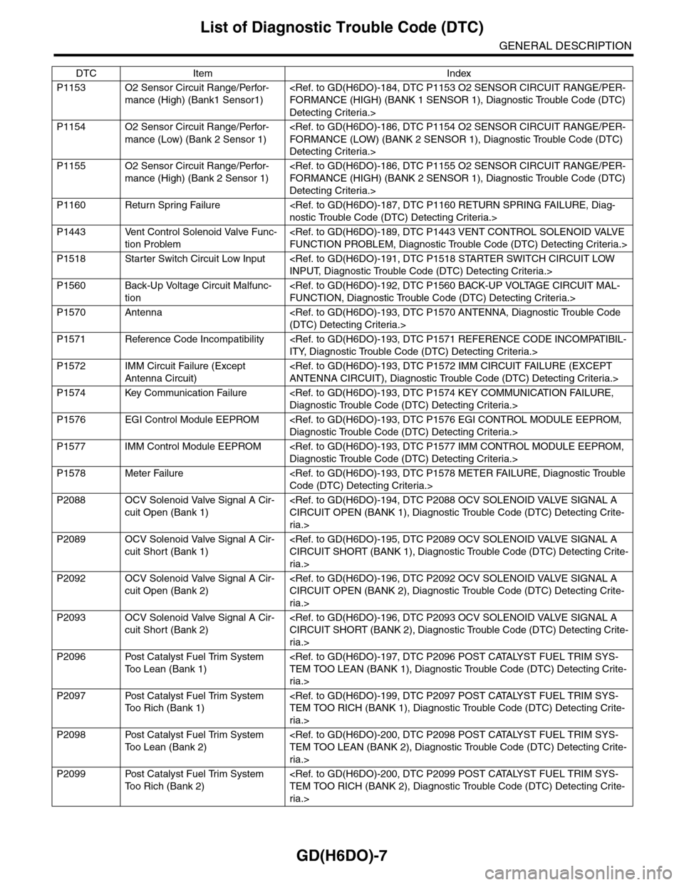
GD(H6DO)-7
List of Diagnostic Trouble Code (DTC)
GENERAL DESCRIPTION
P1153 O2 Sensor Circuit Range/Perfor-
mance (High) (Bank1 Sensor1)
Detecting Criteria.>
P1154 O2 Sensor Circuit Range/Perfor-
mance (Low) (Bank 2 Sensor 1)
Detecting Criteria.>
P1155 O2 Sensor Circuit Range/Perfor-
mance (High) (Bank 2 Sensor 1)
Detecting Criteria.>
P1160 Return Spring Failure
P1443 Vent Control Solenoid Valve Func-
tion Problem
P1518 Starter Switch Circuit Low Input
P1560 Back-Up Voltage Circuit Malfunc-
tion
P1570 Antenna
P1571 Reference Code Incompatibility
P1572 IMM Circuit Failure (Except
Antenna Circuit)
P1574 Key Communication Failure
P1576 EGI Control Module EEPROM
P1577 IMM Control Module EEPROM
P1578 Meter Failure
P2088 OCV Solenoid Valve Signal A Cir-
cuit Open (Bank 1)
ria.>
P2089 OCV Solenoid Valve Signal A Cir-
cuit Short (Bank 1)
ria.>
P2092 OCV Solenoid Valve Signal A Cir-
cuit Open (Bank 2)
ria.>
P2093 OCV Solenoid Valve Signal A Cir-
cuit Short (Bank 2)
ria.>
P2096 Post Catalyst Fuel Trim System
To o L e a n ( B a n k 1 )
ria.>
P2097 Post Catalyst Fuel Trim System
To o R i c h ( B a n k 1 )
ria.>
P2098 Post Catalyst Fuel Trim System
To o L e a n ( B a n k 2 )
ria.>
P2099 Post Catalyst Fuel Trim System
To o R i c h ( B a n k 2 )
ria.>
DTC Item Index
Page 1780 of 2453
GD(H6DO)-168
Diagnostic Trouble Code (DTC) Detecting Criteria
GENERAL DESCRIPTION
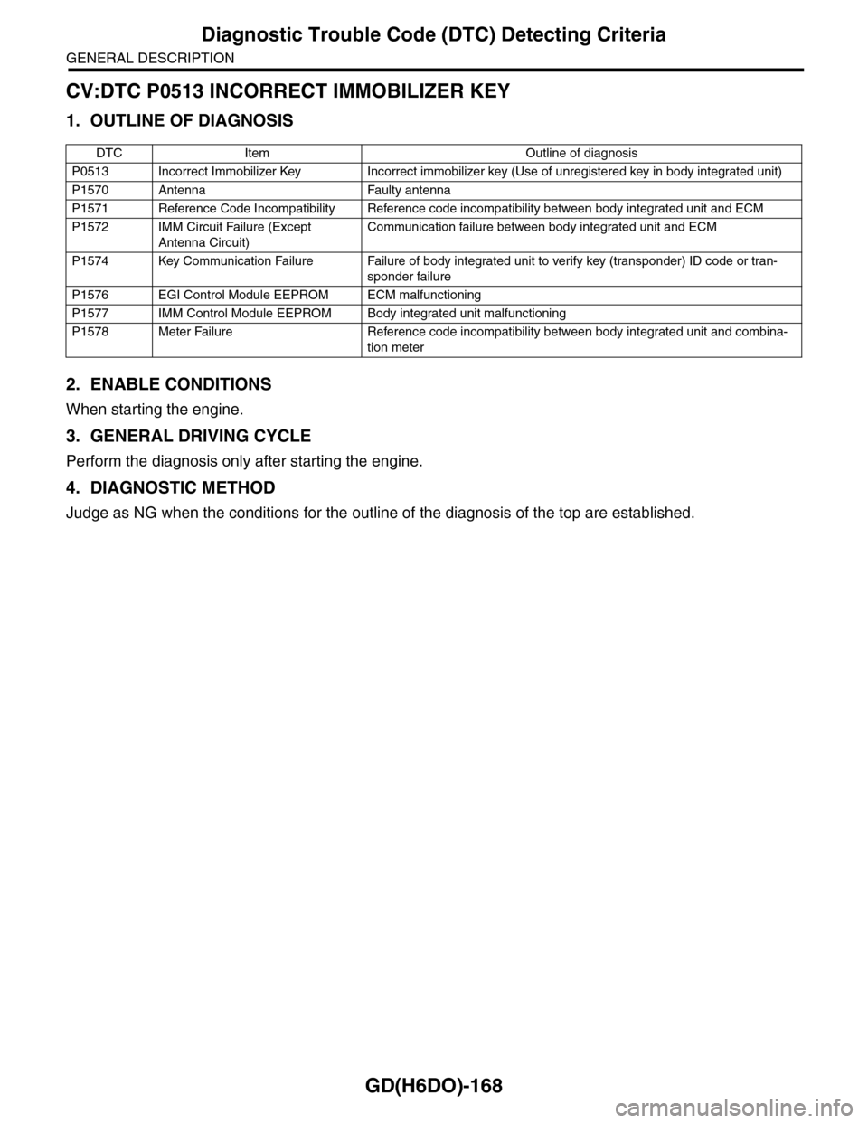
CV:DTC P0513 INCORRECT IMMOBILIZER KEY
1. OUTLINE OF DIAGNOSIS
2. ENABLE CONDITIONS
When starting the engine.
3. GENERAL DRIVING CYCLE
Perform the diagnosis only after starting the engine.
4. DIAGNOSTIC METHOD
Judge as NG when the conditions for the outline of the diagnosis of the top are established.
DTC Item Outline of diagnosis
P0513 Incorrect Immobilizer Key Incorrect immobilizer key (Use of unregistered key in body integrated unit)
P1570 Antenna Faulty antenna
P1571 Reference Code Incompatibility Reference code incompatibility between body integrated unit and ECM
P1572 IMM Circuit Failure (Except
Antenna Circuit)
Communication failure between body integrated unit and ECM
P1574 Key Communication Failure Failure of body integrated unit to verify key (transponder) ID code or tran-
sponder failure
P1576 EGI Control Module EEPROM ECM malfunctioning
P1577 IMM Control Module EEPROM Body integrated unit malfunctioning
P1578 Meter Failure Reference code incompatibility between body integrated unit and combina-
tion meter
Page 1805 of 2453
GD(H6DO)-193
Diagnostic Trouble Code (DTC) Detecting Criteria
GENERAL DESCRIPTION
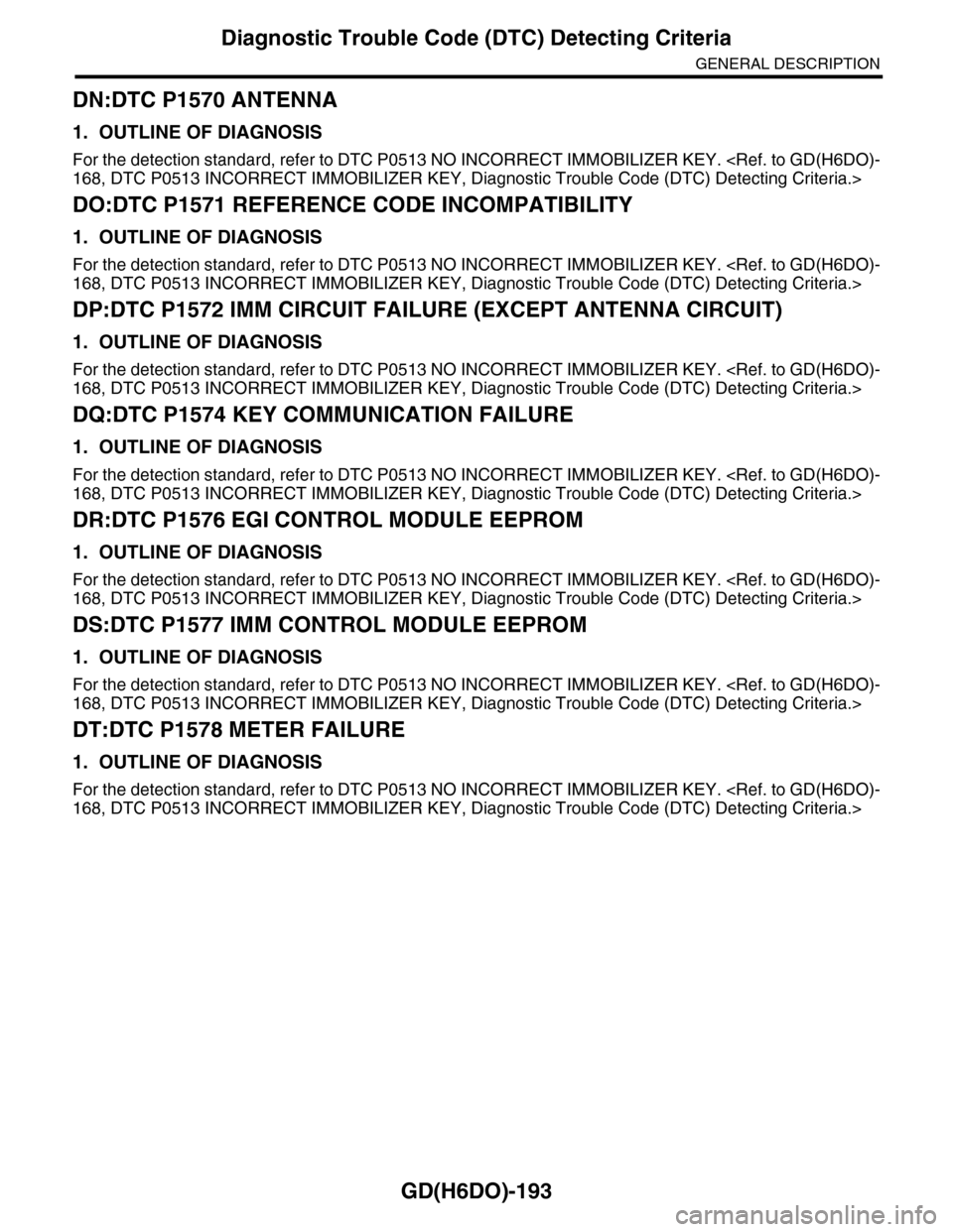
DN:DTC P1570 ANTENNA
1. OUTLINE OF DIAGNOSIS
For the detection standard, refer to DTC P0513 NO INCORRECT IMMOBILIZER KEY.
DO:DTC P1571 REFERENCE CODE INCOMPATIBILITY
1. OUTLINE OF DIAGNOSIS
For the detection standard, refer to DTC P0513 NO INCORRECT IMMOBILIZER KEY.
DP:DTC P1572 IMM CIRCUIT FAILURE (EXCEPT ANTENNA CIRCUIT)
1. OUTLINE OF DIAGNOSIS
For the detection standard, refer to DTC P0513 NO INCORRECT IMMOBILIZER KEY.
DQ:DTC P1574 KEY COMMUNICATION FAILURE
1. OUTLINE OF DIAGNOSIS
For the detection standard, refer to DTC P0513 NO INCORRECT IMMOBILIZER KEY.
DR:DTC P1576 EGI CONTROL MODULE EEPROM
1. OUTLINE OF DIAGNOSIS
For the detection standard, refer to DTC P0513 NO INCORRECT IMMOBILIZER KEY.
DS:DTC P1577 IMM CONTROL MODULE EEPROM
1. OUTLINE OF DIAGNOSIS
For the detection standard, refer to DTC P0513 NO INCORRECT IMMOBILIZER KEY.
DT:DTC P1578 METER FAILURE
1. OUTLINE OF DIAGNOSIS
For the detection standard, refer to DTC P0513 NO INCORRECT IMMOBILIZER KEY.