2009 SUBARU TRIBECA Diff id
[x] Cancel search: Diff idPage 1166 of 2453
EN(H6DO)(diag)-5
General Description
ENGINE (DIAGNOSTICS)
3. General Description
A: CAUTION
1) Airbag system wiring harness is routed near the
ECM, main relay and fuel pump relay.
CAUTION:
•All airbag system wiring harnesses and con-
nectors are colored yellow. Do not use electri-
cal test equipment on these circuits.
•Be careful not to damage the airbag system
wiring harness when servicing the ECM, TCM,
main relay and fuel pump relay.
2) Never connect the battery in reverse polarity.
•The ECM will be destroyed instantly.
•The fuel injector and other parts will be dam-
aged.
3) Do not disconnect the battery terminals while the
engine is running.
A large counter electromotive force will be generat-
ed in the generator, and this voltage may damage
electronic parts such as ECM etc.
4) Before disconnecting the connectors of each
sensor and ECM, be sure to turn the ignition switch
to OFF. Perform the clear memory mode after con-
necting the connectors.
5) Poor contact has been identified as a primary
cause of this problem. Measure the voltage or re-
sistance of individual sensor or all electrical control
modules using a tapered pin with a diameter of less
than 0.64 mm (0.025 in). Do not insert the pin more
than 5 mm (0.20 in) into the part.
6) Remove the ECM from the located position after
disconnecting two cables on battery.
Otherwise, the ECM may be damaged.
CAUTION:
When replacing the ECM, be careful not to use
the wrong spec. ECM to avoid any damage on
the fuel injection system.
7) Connectors of each sensor in the engine com-
partment and the harness connectors on the en-
gine side and body side are all designed to be
waterproof. Even if the connectors are waterproof,
take care not to allow water to get into them when
washing the vehicle, or when servicing the vehicle
in rainy weather.
8) Use ECM mounting stud bolts as the grounding
point to chassis when measuring voltage and resis-
tance in the passenger compartment.
9) Use the engine ground terminal or engine as-
sembly as the grounding point to chassis when
measuring the voltage and resistance in engine
compartment.
10) Every MFI-related part is a precision part. Do
not drop them.
11) Observe the following cautions when installing
a radio in MFI equipped models.
CAUTION:
•The antenna must be kept as far apart as pos-
sible from control unit. (The ECM is located un-
der the steering column, inside of the
instrument panel lower trim panel.)
•The antenna feeder must be placed as far apart
as possible from the ECM and MFI harness.
•Carefully adjust the antenna for correct
matching.
•When mounting a large power type radio, pay
special attention to the three items mentioned
above.
•Incorrect installation of the radio may affect
the operation of ECM.
12) Release the pressure in the fuel system before
disconnecting the fuel hose. If engine starts during
this operation, run it until it stops.
13) For the model with ABS, the ABS warning light
may illuminate when performing driving test with
jacked-up or lifted-up condition, but this is not a
system malfunction. The reason for this is the
speed difference between the front and rear
wheels. After diagnosis of engine control system,
perform the ABS memory clear procedure of self-
diagnosis function.
B: INSPECTION
Before performing diagnostics, check the following
item which might affect engine problems.
1. BATTERY
1) Measure the battery voltage and specific gravity
of electrolyte.
Standard voltage: 12 V
Specific gravity: Above 1.260
2) Check the condition of the main and other fuses,
and harnesses and connectors. Also check for
proper grounding.
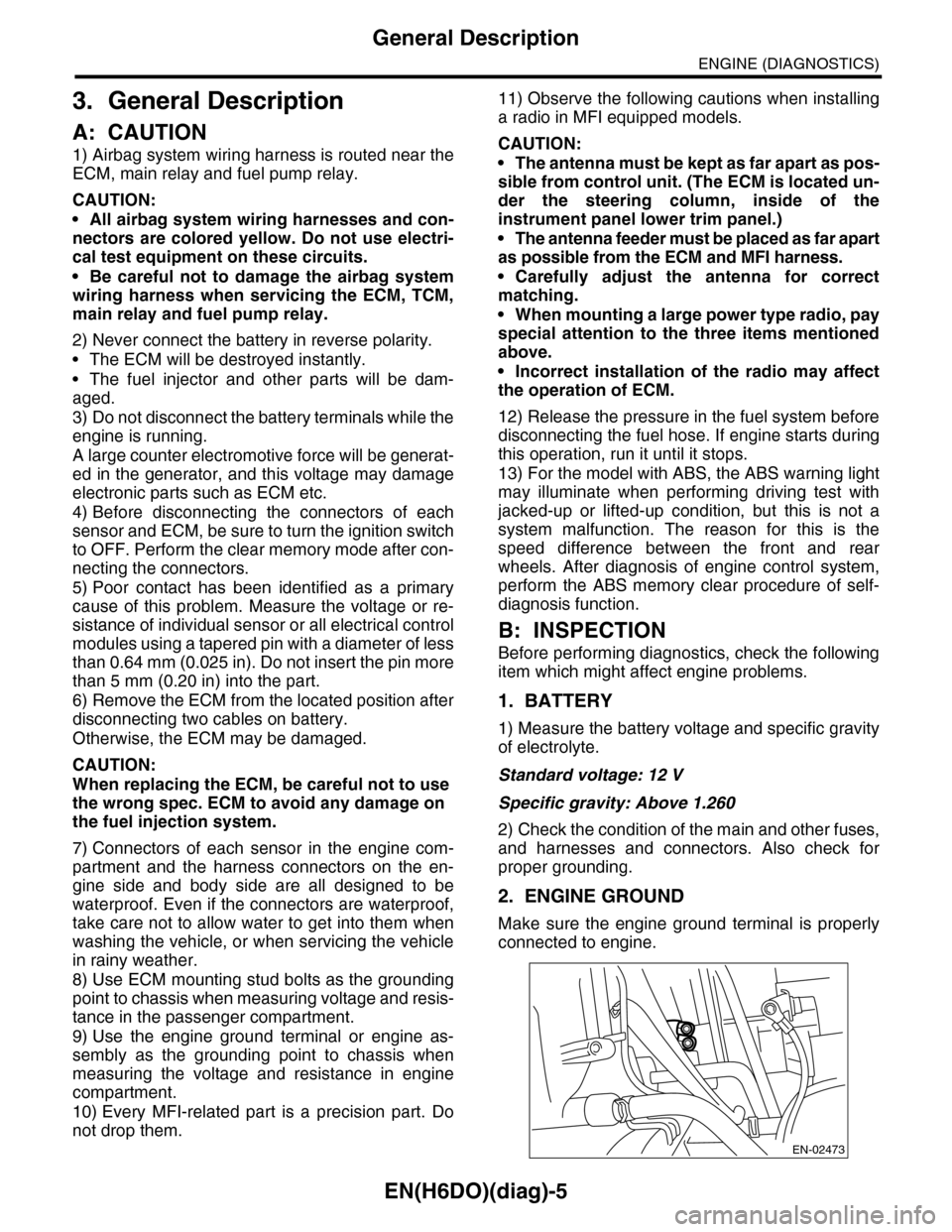
2. ENGINE GROUND
Make sure the engine ground terminal is properly
connected to engine.
EN-02473
Page 1199 of 2453
EN(H6DO)(diag)-38
Inspection Mode
ENGINE (DIAGNOSTICS)
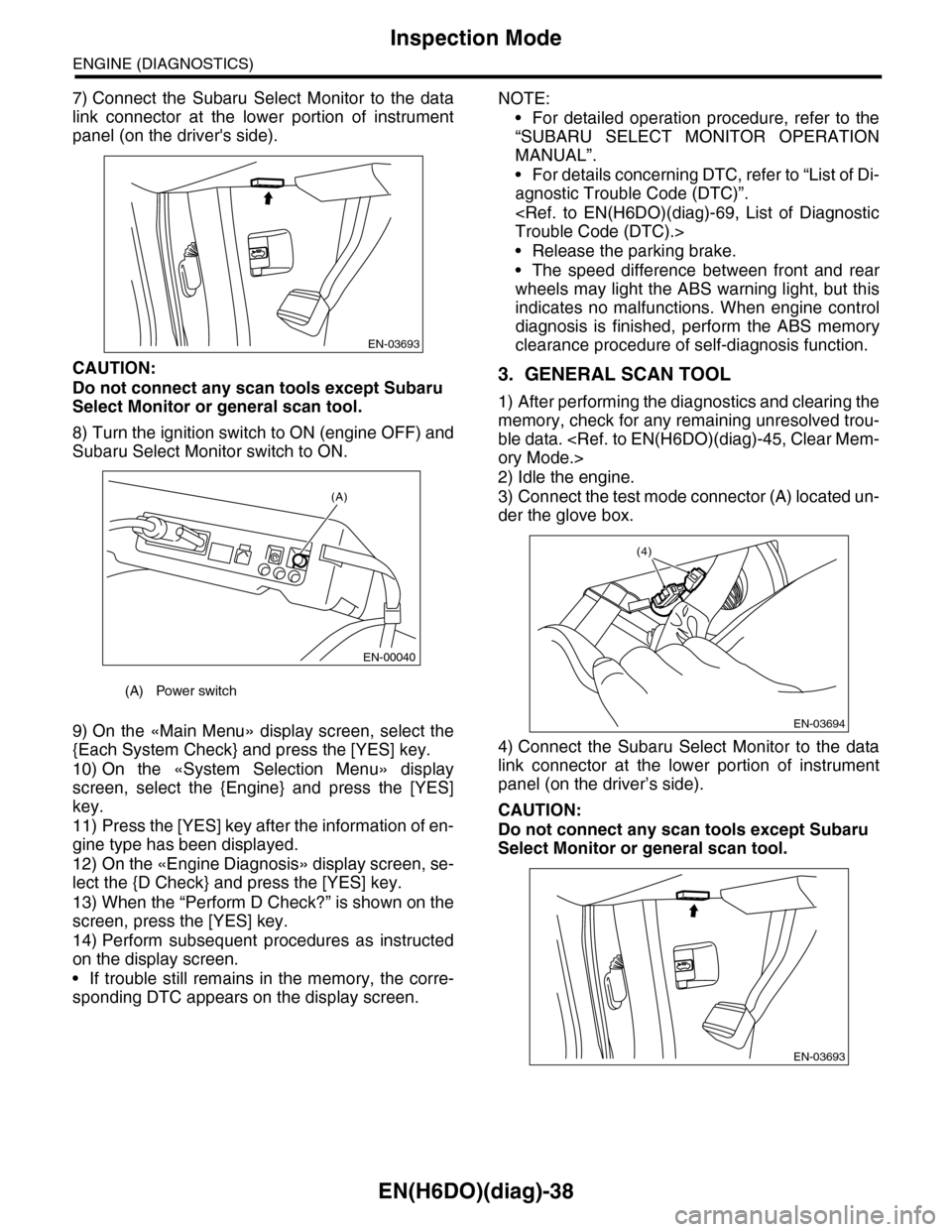
7) Connect the Subaru Select Monitor to the data
link connector at the lower portion of instrument
panel (on the driver's side).
CAUTION:
Do not connect any scan tools except Subaru
Select Monitor or general scan tool.
8) Turn the ignition switch to ON (engine OFF) and
Subaru Select Monitor switch to ON.
9) On the «Main Menu» display screen, select the
{Each System Check} and press the [YES] key.
10) On the «System Selection Menu» display
screen, select the {Engine} and press the [YES]
key.
11) Press the [YES] key after the information of en-
gine type has been displayed.
12) On the «Engine Diagnosis» display screen, se-
lect the {D Check} and press the [YES] key.
13) When the “Perform D Check?” is shown on the
screen, press the [YES] key.
14) Perform subsequent procedures as instructed
on the display screen.
•If trouble still remains in the memory, the corre-
sponding DTC appears on the display screen.
NOTE:
•For detailed operation procedure, refer to the
“SUBARU SELECT MONITOR OPERATION
MANUAL”.
•For details concerning DTC, refer to “List of Di-
agnostic Trouble Code (DTC)”.
•Release the parking brake.
•The speed difference between front and rear
wheels may light the ABS warning light, but this
indicates no malfunctions. When engine control
diagnosis is finished, perform the ABS memory
clearance procedure of self-diagnosis function.
3. GENERAL SCAN TOOL
1) After performing the diagnostics and clearing the
memory, check for any remaining unresolved trou-
ble data.
2) Idle the engine.
3) Connect the test mode connector (A) located un-
der the glove box.
4) Connect the Subaru Select Monitor to the data
link connector at the lower portion of instrument
panel (on the driver’s side).
CAUTION:
Do not connect any scan tools except Subaru
Select Monitor or general scan tool.
(A) Power switch
EN-03693
(A)
EN-00040
EN-03694
(4)
EN-03693
Page 1200 of 2453
EN(H6DO)(diag)-39
Inspection Mode
ENGINE (DIAGNOSTICS)
5) Start the engine.
NOTE:
Make sure the select lever is placed in “P” position
before starting.
6) Using the select lever, turn the “P” position
switch and the “N” position switch to ON.
7) Depress the brake pedal to turn brake switch
ON.
8) Keep the engine speed in 2,500 — 3,000 rpm
range for 40 seconds.
9) Shift the select lever in the “D” range and drive
the vehicle at 5 to 10 km/h (3 to 6 MPH).
NOTE:
•For AWD model, release the parking brake.
•The speed difference between front and rear
wheels may light the ABS warning light, but this in-
dicates no malfunctions. When engine control diag-
nosis is finished, perform the ABS memory
clearance procedure of self-diagnosis system.
10) Using the general scan tool, check DTC and
record the result(s).
NOTE:
•For detailed operation procedure, refer to the
general scan tool operation manual.
•For details concerning DTC, refer to “List of Diag-
nostic Trouble Code (DTC)”.
Page 1654 of 2453
GD(H6DO)-42
Diagnostic Trouble Code (DTC) Detecting Criteria
GENERAL DESCRIPTION
AA:DTC P0111 INTAKE AIR TEMPERATURE CIRCUIT RANGE/PERFORMANCE
1. OUTLINE OF DIAGNOSIS
Detect the malfunction of intake air temperature sensor output property.
Judge as NG when the intake air temperature is not varied whereas it seemed to be varied from the viewpoint
of engine condition.
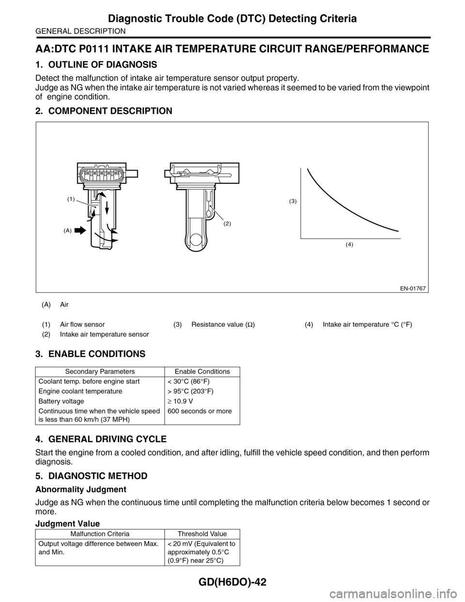
2. COMPONENT DESCRIPTION
3. ENABLE CONDITIONS
4. GENERAL DRIVING CYCLE
Start the engine from a cooled condition, and after idling, fulfill the vehicle speed condition, and then perform
diagnosis.
5. DIAGNOSTIC METHOD
Abnormality Judgment
Judge as NG when the continuous time until completing the malfunction criteria below becomes 1 second or
more.
(A) Air
(1) Air flow sensor (3) Resistance value (Ω)(4)Intake air temperature °C (°F)
(2) Intake air temperature sensor
Secondary Parameters Enable Conditions
Coolant temp. before engine start < 30°C (86°F)
Engine coolant temperature > 95°C (203°F)
Battery voltage≥ 10.9 V
Continuous time when the vehicle speed
is less than 60 km/h (37 MPH)
600 seconds or more
Judgment Value
Malfunction Criteria Threshold Value
Output voltage difference between Max.
and Min.
< 20 mV (Equivalent to
approximately 0.5°C
(0.9°F) near 25°C)
EN-01767
(3)
(4)
(2)
(1)
(A)
Page 1655 of 2453
GD(H6DO)-43
Diagnostic Trouble Code (DTC) Detecting Criteria
GENERAL DESCRIPTION
Time Needed for Diagnosis: 1 second
Malfunction Indicator Light Illumination: Illuminates when malfunctions occur in 2 continuous driving cy-
cles.
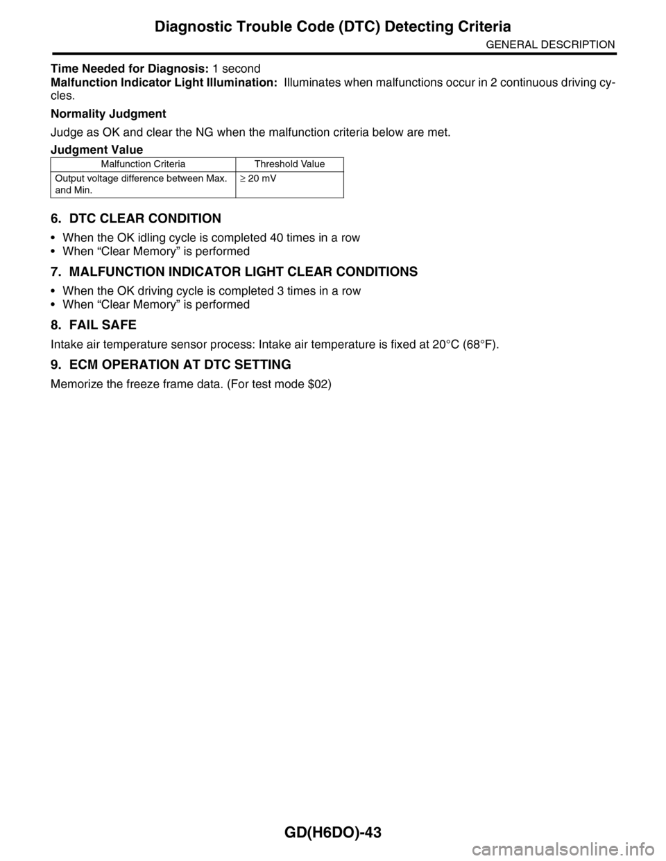
Normality Judgment
Judge as OK and clear the NG when the malfunction criteria below are met.
6. DTC CLEAR CONDITION
•When the OK idling cycle is completed 40 times in a row
•When “Clear Memory” is performed
7. MALFUNCTION INDICATOR LIGHT CLEAR CONDITIONS
•When the OK driving cycle is completed 3 times in a row
•When “Clear Memory” is performed
8. FAIL SAFE
Intake air temperature sensor process: Intake air temperature is fixed at 20°C (68°F).
9. ECM OPERATION AT DTC SETTING
Memorize the freeze frame data. (For test mode $02)
Judgment Value
Malfunction Criteria Threshold Value
Output voltage difference between Max.
and Min.
≥ 20 mV
Page 1672 of 2453
GD(H6DO)-60
Diagnostic Trouble Code (DTC) Detecting Criteria
GENERAL DESCRIPTION
AJ:DTC P0128 COOLANT THERMOSTAT (COOLANT TEMPERATURE BELOW
THERMOSTAT REGULATING TEMPERATURE)
1. OUTLINE OF DIAGNOSIS
Detect malfunctions of the thermostat.
Judge as NG when the engine coolant temperature is lower than the estimated engine coolant temperature
and the difference between them is large. Judge as OK when the engine coolant temperature becomes to
75°C (167°F), and the difference is small, before judging NG.
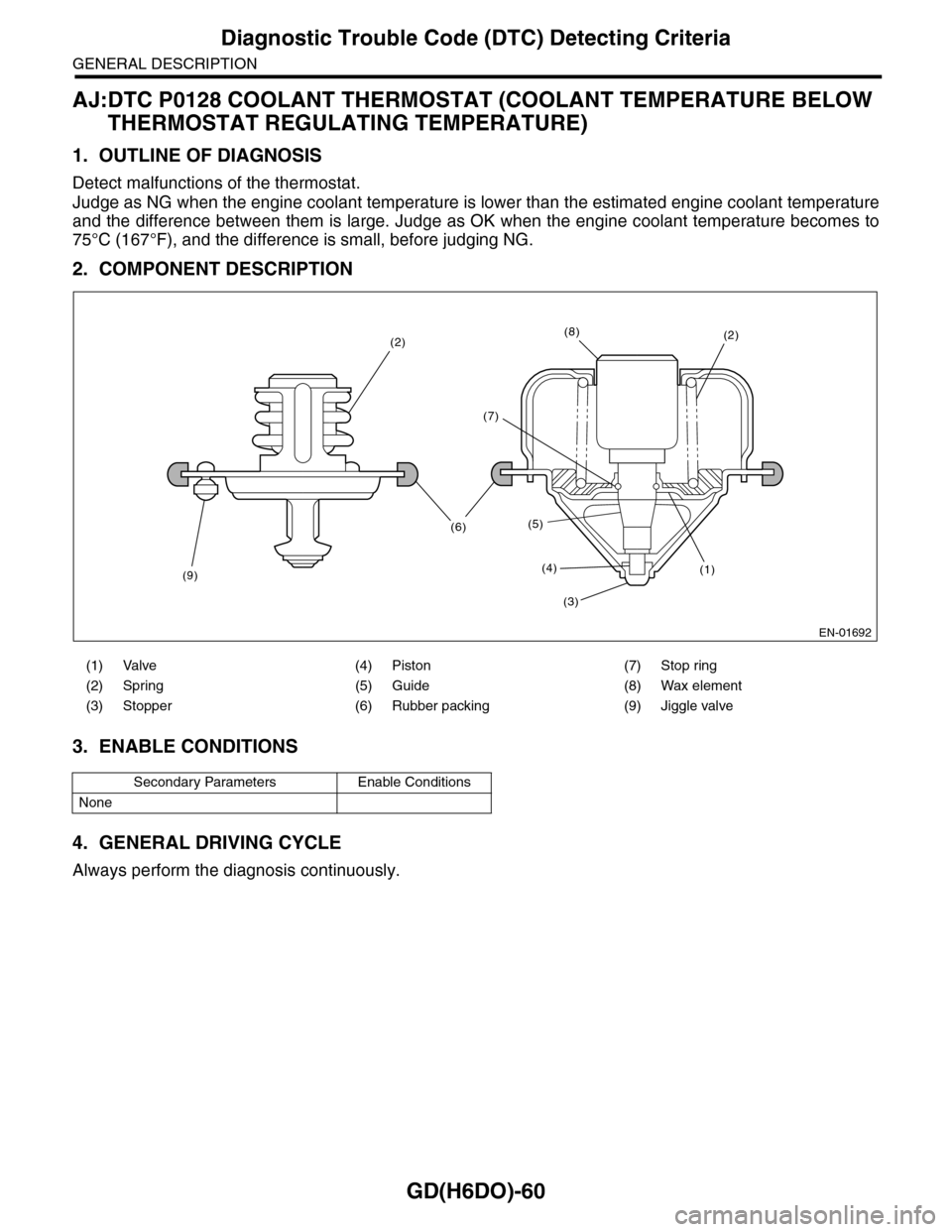
2. COMPONENT DESCRIPTION
3. ENABLE CONDITIONS
4. GENERAL DRIVING CYCLE
Always perform the diagnosis continuously.
(1) Valve (4) Piston (7) Stop ring
(2) Spring (5) Guide (8) Wax element
(3) Stopper (6) Rubber packing (9) Jiggle valve
Secondary Parameters Enable Conditions
None
EN-01692
(9)
(2)
(6)
(8)
(7)
(5)
(4)
(3)
(1)
(2)
Page 1680 of 2453
GD(H6DO)-68
Diagnostic Trouble Code (DTC) Detecting Criteria
GENERAL DESCRIPTION
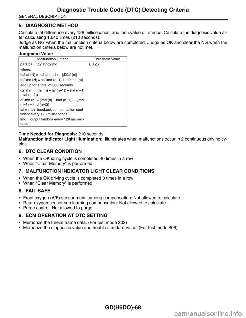
5. DIAGNOSTIC METHOD
Calculate faf difference every 128 milliseconds, and the λvalue difference. Calculate the diagnosis value af-
ter calculating 1,640 times (210 seconds).
Judge as NG when the malfunction criteria below are completed. Judge as OK and clear the NG when the
malfunction criteria below are not met.
Time Needed for Diagnosis: 210 seconds
Malfunction Indicator Light Illumination: Illuminates when malfunctions occur in 2 continuous driving cy-
cles.
6. DTC CLEAR CONDITION
•When the OK idling cycle is completed 40 times in a row
•When “Clear Memory” is performed
7. MALFUNCTION INDICATOR LIGHT CLEAR CONDITIONS
•When the OK driving cycle is completed 3 times in a row
•When “Clear Memory” is performed
8. FAIL SAFE
•Front oxygen (A/F) sensor main learning compensation: Not allowed to calculate.
•Rear oxygen sensor sub learning compensation: Not allowed to calculate.
•Purge control: Not allowed to purge
9. ECM OPERATION AT DTC SETTING
•Memorize the freeze frame data. (For test mode $02)
•Memorize the diagnostic value and trouble standard value. (For test mode $06)
Judgment Value
Malfunction Criteria Threshold Value
parafca = td2faf/td2lmd≥ 0.25
where,
td2faf (N) = td2faf (n–1) + |d2faf (n)|
td2lmd (N) = td2lmd (n–1) + |d2lmd (n)|
add up for a total of 300 seconds
d2faf (n) = (faf (n) – faf (n–1)) – (faf (n–1)
– faf (n–2))
d2lmd (n) = (lmd (n) – lmd (n–1)) – (lmd
(n–1) – lmd (n–2))
faf = main feedback compensation coef-
ficient every 128 milliseconds
lmd = output lambda every 128 millisec-
onds
Page 1701 of 2453
GD(H6DO)-89
Diagnostic Trouble Code (DTC) Detecting Criteria
GENERAL DESCRIPTION
8. DIAGNOSTIC METHOD
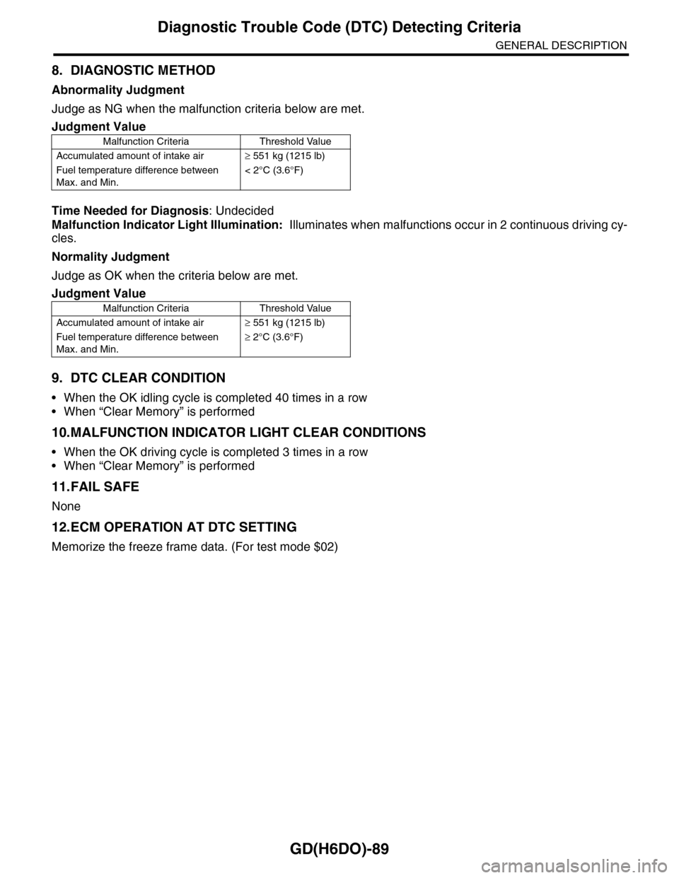
Abnormality Judgment
Judge as NG when the malfunction criteria below are met.
Time Needed for Diagnosis: Undecided
Malfunction Indicator Light Illumination: Illuminates when malfunctions occur in 2 continuous driving cy-
cles.
Normality Judgment
Judge as OK when the criteria below are met.
9. DTC CLEAR CONDITION
•When the OK idling cycle is completed 40 times in a row
•When “Clear Memory” is performed
10.MALFUNCTION INDICATOR LIGHT CLEAR CONDITIONS
•When the OK driving cycle is completed 3 times in a row
•When “Clear Memory” is performed
11.FAIL SAFE
None
12.ECM OPERATION AT DTC SETTING
Memorize the freeze frame data. (For test mode $02)
Judgment Value
Malfunction Criteria Threshold Value
Accumulated amount of intake air≥ 551 kg (1215 lb)
Fuel temperature difference between
Max. and Min.
< 2°C (3.6°F)
Judgment Value
Malfunction Criteria Threshold Value
Accumulated amount of intake air≥ 551 kg (1215 lb)
Fuel temperature difference between
Max. and Min.
≥ 2°C (3.6°F)